Hobart FP350 Food Processor Manuel utilisateur
- Taper
- Manuel utilisateur

701 S. RIDGE AVENUE
TROY, OHIO 45373
937 332-3000
www.hobartcorp.com FORM 19353 Rev. F (December 2023)
FP350 FOOD PROCESSOR
MODEL FP350 ML-104586

– 2 –
© HOBART, 2023
TABLE OF CONTENTS
GENERAL .............................................................................................................................................................. 3
INSTALLATION .....................................................................................................................................................4
Unpacking ........................................................................................................................................................4
Moving .............................................................................................................................................................4
Location ...........................................................................................................................................................4
Electrical Connections .....................................................................................................................................4
OPERATION .........................................................................................................................................................6
Controls (Fig. 2) ...............................................................................................................................................6
Fitting and Removing the Pusher Plate ...........................................................................................................6
Fitting and Removing the Cutting Tools ...........................................................................................................7
Using the Feed Cylinder ..................................................................................................................................8
Using the Feed Tube ........................................................................................................................................ 8
Cutting Tool Guide............................................................................................................................................9
CLEANING ..........................................................................................................................................................10
MAINTENANCE ..................................................................................................................................................11
Weekly Check ................................................................................................................................................11
Replacement Dicing Grids .............................................................................................................................11
TROUBLESHOOTING .......................................................................................................................................12
Service ...........................................................................................................................................................12

– 3 –
Installation, Operation and Care of
MODEL FP350 FOOD PROCESSOR
SAVE THESE INSTRUCTIONS
GENERAL
The model FP350 Food Processor can process vegetables, fruit, bread, cheese and nuts. Its sleek, angled
design allows food to be loaded easily into either a narrow feed tube or a full size feed hopper.
Various cutting plates can be used to slice, dice, grate, shred, julienne and make regular-cut and crinkle
cut potato chips and french fries. In addition, the pusher plate has an assisting mechanism that reduces
the pressure needed to push food onto the cutting plates.
The Food Processor also has two built-in interlocks. An automatic start-stop interlock stops the food
processor when the pusher plate is raised and swung away from the feed hopper and restarts the food
processor when the pusher plate is moved back over and into the hopper. The other interlock keeps the
food processor turned o until the feed hopper is placed in the correct position.
To save space, wall-mounted storage racks are available. Each rack can hold three cutting plates.

– 4 –
INSTALLATION
UNPACKING
The food processor was inspected before leaving the factory. The carrier assumes full responsibility for safe
delivery upon acceptance of the shipment. Check for possible shipping damage immediately after receipt.
If the food processor is found to be damaged, complete the following steps:
1. Carrier must be notied within ve business days of receipt.
2. Carrier’s local terminal must be notied immediately upon discovery (note the time, date, and who
was spoken to), and follow up and conrm with written or electronic communication.
3. All original packing materials must be kept for inspection purposes.
4. The food processor cannot have been moved, installed, or modied.
5. Notify Hobart customer care at (800) 333-7447.
Prior to installing the food processor, verify that the electrical service agrees with the specications on the
machine data plate, which is located on the back of the machine.
Check that the cutting tools are in good condition and are sharp.
MOVING
To lift and move the food processor, grasp the handle at the back of the base with one hand and grasp
the discharge chute on the front with the other hand.
LOCATION
The FP350 should be operated on a suitable counter height surface. A pan (not provided), suitable for
kitchen use, can be used to capture the product at the exit chute.
ELECTRICAL CONNECTIONS
The electrical cord on this machine is equipped with a grounding- type plug which
must be connected to a properly grounded receptacle. If the receptacle is not the proper grounding
type, contact an electrician. Do not remove the grounding prong from the plug.
ELECTRICAL DATA
Model Volts Hertz Phase Amps
FP350 120 60 1 10

– 5 –
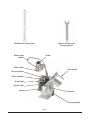
Fig. 1
Wrench for removing
Decoring Screw
Wall Rack for Cutting Tool
Carrying Handle
Controls
Feed Hopper
Pestle
Chute
Ejector Plate
Knife Shaft
Knife Chamber
Decoring Screw
Pusher Plate
Pusher Plate
Handle

– 6 –
OPERATION
Rotating knives inside. Always use pusher plate. Keep hands out.
Proper assembly of the FP350, including selection of the appropriate cutters, is necessary for correct
operation of the food processor. Refer to the Cutting Tool Guide for sizes of cutters and refer to the
appropriate operation instructions.
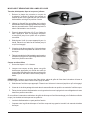
CONTROLS (FIG. 2)
START (Green) — Push to start.
STOP (Red) — Push to stop.
Interlock switches prevent the food processor from operating
when the feed cylinder is out of position or the pusher plate is
raised above the feed cylinder. If these features do not function
as described, contact your local Hobart Service Oce.
During operation, when the pusher plate is fully raised above
the feed cylinder, the food processor stops and allows the pusher
plate to be rotated clockwise for loading. To continue operation,
rotate the pusher plate counterclockwise until it is directly above
the feed cylinder. As the pusher plate begins to lower into the feed cylinder, the food processor will restart
— you do not need to push the green START switch unless STOP was pressed.
Always push the red STOP switch before changing cutters or
cleaning.
FITTING AND REMOVING THE PUSHER PLATE
1. To t the pusher plate, you MUST hold it with both hands
in the exact positions shown in Fig. 3. Hold it with the
pusher plate handle to the left of the machine (as you face
the front). Position the pusher plate shaft against the
bracket on the food processor.
2. Push the pusher plate down on the shaft with your right
hand as far as it will go (Fig. 4). The pin on the shaft of
the pusher plate must slide into the slot in the bracket.
3. To remove the pusher plate, hold the pusher plate handle,
raise the pusher plate and swing it out to the left so that
the feed cylinder is set in the open position.
4. Take hold of the pusher plate with both hands (Fig. 3).
5. Rotate pusher plate until the pin on the shaft is out of the
slot on the bracket. Pull the pusher plate up and away
with the right hand.
Fig. 2
Fig. 3
Fig. 4

– 7 –
FITTING AND REMOVING THE CUTTING TOOLS
Slicing, Shredding, Grating, and Julienne Cutting
1. Using the pusher plate handle, raise the pusher
plate and swing it to the left so that the feed
cylinder is set in the open position.
2. Release the feed cylinder lock by turning the
lock handle counterclockwise. Then swing the
feed cylinder out to the right.
3. Place the ejector plate (Fig. 5) on the knife shaft.
Press the ejector plate all the way down and turn
until the plate is in the locked position.
4. Select the appropriate cutting tool for the job.
Place it on the shaft, turning until engaged.
5. Screw the decoring screw (Fig. 6) hand tight
counterclockwise into position in the cutting tool
center.
6. Swing the feed cylinder back to the left and turn
the lock handle clockwise into locked position.
Dicing and French Fries
1. Follow Steps 1 through 3 above.
2. When dicing, place a suitable dicing grid (see
Cutting Tool Guide) in the knife chamber and
turn the dicing grid clockwise as far as it will go.
NOTE: When cutting straight potato chips, place the
potato chip grid in the knife chamber and turn the potato
chip grid clockwise as far as it will go.
3. Select the appropriate cutting tool. Place it on the shaft, turning until engaged.
4. Screw the decoring screw hand tight counterclockwise into position in the cutting tool center.
5. Swing the feed cylinder back to the left and turn the lock handle clockwise into locked position.
If you use the wrong combination of dicing grid and slicing tool (see Cutting Tool Guide), the following
may result:
• The feed cylinder cannot be closed.
• The space between the dicing grid and the slicing tool is too large and leads to poor cutting results.
Fig. 5
Fig. 6

– 8 –
Removing the Cutting Tools
1. Using the pusher plate handle, raise the pusher
plate and swing it out to the left so that the feed
cylinder is set in the open position.
2. Turn the lock handle counterclockwise and swing
the feed cylinder out to the right.
3. Using the wrench (Fig. 7) supplied, loosen the
decoring screw in a clockwise direction.
4. Remove the cutting tool(s) and the ejector plate.
USING THE FEED CYLINDER
After the pusher plate is raised, prepared products, such as potatoes, carrots, onions, lettuce, cabbage,
etc., can be placed in the large feed cylinder.
When cutting French fries with the Julienne cutter, place/pile the potatoes against the partition wall. The
potatoes may be stacked to cut several at one time. For consistent results, stack product against the
partition wall of the feed cylinder, one pile only.
The large feed cylinder is also used to slice round products, such as lemons and tomatoes. Position the
product against the partition wall of the feed cylinder. For best results, it is advisable to remove tops and
tails from round products like lemons, limes, or onions and place them in the feed cylinder perpendicular
to the desired cut.
A light pressure on the pusher plate is all that is required to give the best cutting results.
USING THE FEED TUBE
Use the feed tube when cutting elongated items such as cucumber, leek, etc.
Since the food processor does not stop when the pestle for the feed tube is removed, you may use the
feed tube for continuous feeding/cutting. Always use the pestle to push foods through the feed tube.
Fig. 7

– 9 –
CUTTING TOOL GUIDE
Crimping Slicer — 3/16" (4.5 MM)
For ripple slicing of root vegetables.
Fine Slicer (2 Blade) — 1/16" (1.5 MM)
For slicing rm or fragile products. Also for use with 9/32" dicing plate. Makes very thin slices of
pepperoni, mushrooms, cabbage, potatoes, cucumbers and radishes.
Fine Slicer (1 Blade) — 5/32" (4 MM), 9/16" (14 MM), 1/8" (3 MM), 7/32" (6 MM), 3/8" (10 MM)
Use is same as 2-blade ne slicer. Also slices soft and/or juicy products such as tomato,
lemon and banana. Shreds lettuce. Dices in combination with 5/32" dicing grid. Chops onion in
combination with 3/8" dicing grid.
Julienne Cutter —
3/32" (2 MM) — Makes various salad toppings.
3/16" (4.5 MM) — Makes shoestring French fries.
5/16" (8 MM) — Makes French fries.
Dicing Grid — Dices in combination with dicing cutter or ne cut slicer. The dicer grid dimension
must be equal to, or larger than, the slicer dimension.
9/32" (7.5 MM) (use with 7/32" or smaller Slicer) — For thin diced vegetables (carrots,
celery, onions, potatoes and vegetables for soup).
3/8" (10 MM) (use with 3/8" or smaller Slicer) — Good for dicing rm chilled tomatoes.
3/4" (20 MM) (use only with 9/16" Slicer) — Prepares tomatoes, potatoes for home fries
or potato salad and dices apples or melon.
5/8" (15 MM) (use with 3/8" or smaller Slicer) — Dices tomatoes, apples, melon and other
fruits for salads, pies or other uses.
Grater — Fine
Makes grated Parmesan or Romano cheese (hard cheese only).
Shredder — Shredder plates are used to process cheese for toppings and salad bar items,
cabbage for coleslaw, potatoes for hash browns or potato pancakes.
1/16" (1.5 MM) — Makes extra ne shredded cheese for sandwich topping or other uses.
3/32" (2 MM) — Makes ne breadcrumbs and cracker crumbs for use in cooking. Use when
machine and product are dry.
1/8" (3 MM) — Medium shredder for various uses.
3/16" (4.5 MM) — Makes pizza toppings and salad bar items.
5/16" (8 MM) — Shreds cabbage and soft pizza cheese.
7/32" (6 MM) — Shreds carrot, dry bread, almonds, nuts, and soft pizza cheese.
A wall rack is available to hang the cutting tools for easy access of the operator and to protect sharpness of the blades.

– 10 –
CLEANING
Turn the machine o and unplug the electrical cord before cleaning.
Do not clean stainless steel with bleach-containing cleansers like automatic dishwashing
detergent: Bleach can corrode stainless steel. Do not clean the aluminum parts with high-alkaline detergents
like automatic dishwashing detergent or with hot water: Black aluminum oxide can form. Removable parts
should be handwashed in a three-part sink and should not be put into the dishwasher with the exception
of cutting tools and the decoring screw.
Clean the machine immediately after each use. Dismantle all removable parts from the machine and wash
them in warm water and detergent. Rinse thoroughly and wipe dry with a soft clean cloth.
Allowing food juices to dry on the machine may cause discoloration.
DO NOT USE steel wool or sharp objects for cleaning machine surfaces if they become discolored;
scratched surfaces become hard to keep clean.
Do not leave the cutting blades in a wet condition when not in use.
Never clean the machine with a high pressure hose, with steam injection equipment, or in a dishwasher.
Always store the cutting tools on the wall racks for safe handling and easy access.
1. Remove pestle; wash in warm water and detergent then rinse in lukewarm water.
2. Remove the pusher plate and then the feed cylinder; wash in warm water and detergent then rinse
in lukewarm water.
3. Remove the cutting tool.
4. If you have used a dicing grid, before removing, push the remaining leftovers through the TOP of
the dicing grid with the nylon brush. Pushing the leftovers through from the underside of the dicing
grid may damage the grid.
5. Remove the dicing grid and ejector plate; wash in warm water and detergent then rinse in lukewarm
water.
6. Wipe the knife chamber with a clean damp cloth. Wipe dry with a clean dry cloth.
7. Return the cutting tools to the wall rack. Lower the ejector plate onto the knife shaft. Press all the
way down and turn until the plate is in the locked position.
8. Replace the feed cylinder and the pusher plate.

– 11 –
MAINTENANCE
WEEKLY CHECK
1. With the power cord connected to the outlet, test the interlock switches.
2. The remaining checks must be performed with the power cord unplugged from the outlet.
Turn the machine o and unplug the electrical cord before doing any maintenance.
3. Inspect the power cord and make sure it is in good shape. Look for cuts, fraying or cracking.
4. Make sure the pusher plate shaft moves freely. If it does not, clean and dry it and lubricate with
several drops of mineral oil.
5. Make sure the cutting plate blades are sharp. If not, have them sharpened or the cutting plate
replaced.
The knife shaft should be regularly lubricated with a drop of mineral oil, NOT COOKING OIL.
REPLACEMENT DICING GRIDS
Depending on usage, dicing grids become dull from wear with an average life expectancy from 8 – 18
months. Dicing grids cannot be resharpened and are therefore expendable. Replacement dicing grids are
available from your local Hobart Service oce.

FORM 19353 Rev. F (December 2023) PRINTED IN U.S.A.
SERVICE
Contact your local Hobart Service Oce for any repairs or adjustments needed on this equipment. Long-
term service contracts are available on this and other Hobart products.
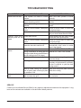
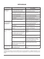
TROUBLESHOOTING
SYMPTOM POSSIBLE CAUSE SUGGESTED ACTION
Machine will not start. Feed cylinder not locked in correct
position.
Make sure feed cylinder is locked
correctly.
Pusher plate or feed cylinder not in
proper operating position.
Fit pusher plate into proper operating
position.
Pusher plate swung out beside feed
cylinder.
Swing pusher plate into feed cylinder
center.
Fuse or circuit breaker interrupting
power.
Check for blown fuses or fuses with
wrong amperage.
Broken wire or connection. Pull electrical cord from receptacle and
call your local Hobart Service Oce.
Machine stops while
operating and will not
restart.
Pusher plate raised. Swing pusher plate into feed cylinder
center and lower pusher plate.
Fuse or circuit breaker interrupting
power.
Check for blown fuse or fuses with
wrong Amperage.
Motor overloaded and thermal motor
protection has shut machine o.
Thermal motor protection will
automatically allow motor to restart
when it has cooled.
Low output or bad cutting
results.
Wrong cutting tool used. Refer to CUTTING TOOL GUIDE.
Wrong combination of dicing grid and
slicing tool when dicing (space between
the two cutting tools is too large).
Refer to CUTTING TOOL GUIDE.
Problem with blade or grating plate. Make sure blades or grating plates are
intact and sharp.
Feeding pressure too heavy. Provided the blades and grating plates
are sharp, a light pressure is normally
all that is required to yield the best
cutting results.
Build-up under cutting tool, possibly
due to ejector plate not being in place
or container is full.
Make sure the ejector plate is always
tted when cutting.
Cutting tool locked to
shaft.
Build-up between cutting tool and dicing
grid or potato chip grid.
With a little force, carefully rotate cutting
tool clockwise.

701 S. RIDGE AVENUE
TROY, OHIO 45373
937 332-3000
www.hobartcorp.com FORMULARIO 19353 Rev. F (Diciembre de 2023)
PROCESADOR DE ALIMENTOS FP350
MODELO FP350 ML-104586

– 2 –
© HOBART, 2023
TABLA DE CONTENIDO
GENERAL .............................................................................................................................................................. 3
INSTALACIÓN ......................................................................................................................................................4
Desembalaje ....................................................................................................................................................4
Traslado ...........................................................................................................................................................4
Ubicación .........................................................................................................................................................4
Conexiones eléctricas ......................................................................................................................................4
FUNCIONAMIENTO .............................................................................................................................................6
Controles (Fig. 2) .............................................................................................................................................6
Montaje y desmontaje de la placa empujadora ...............................................................................................6
Montaje y desmontaje de las herramientas de corte .......................................................................................7
Uso del cilindro de alimentación ......................................................................................................................8
Uso del tubo de alimentación ........................................................................................................................... 8
Guía de herramientas de corte ........................................................................................................................9
LIMPIEZA ............................................................................................................................................................10
MANTENIMIENTO ..............................................................................................................................................11
Control semanal ............................................................................................................................................. 11
Reemplazo de los discos de cubeado ...........................................................................................................11
RESOLUCIÓN DE PROBLEMAS ......................................................................................................................12
Servicio ..........................................................................................................................................................12

– 3 –
Instalación, funcionamiento y cuidado del
PROCESADOR DE ALIMENTOS MODELO FP350
CONSERVE ESTAS INSTRUCCIONES
GENERAL
El procesador de alimentos Modelo FP350 puede procesar verduras, frutas, pan, queso y frutos secos. Su
diseño elegante y anguloso permite cargar fácilmente los alimentos en un tubo de alimentación estrecho
o en una tolva de alimentación de tamaño completo.
Se pueden utilizar varios discos de corte para rebanar, cortar en cubos, rallar, desmenuzar, cortar en
juliana, y hacer papas fritas de corte regular y de corte ondulado. Además, la placa empujadora tiene un
mecanismo de ayuda que reduce la presión necesaria para empujar los alimentos hacia los discos de corte.
El procesador de alimentos también cuenta con dos enclavamientos incorporados. Un enclavamiento
automático de arranque-parada detiene el procesador de alimentos cuando la placa empujadora se
levanta y se aleja de la tolva de alimentación, y vuelve a ponerlo en marcha cuando la placa empujadora
se mueve de nuevo hacia la tolva. El otro enclavamiento mantiene el procesador de alimentos apagado
hasta que la tolva de alimentación se coloca en la posición correcta.
Para ahorrar espacio, existen soportes de almacenamiento montados en la pared. Cada soporte puede
albergar tres discos de corte.

– 4 –
INSTALACIÓN
DESEMBALAJE
El procesador de alimentos fue inspeccionado antes de salir de fábrica. El transportista asume total
responsabilidad por la entrega segura una vez aceptado el cargamento. Compruebe que no haya daños
al cargamento inmediatamente después de recibirlo.
Si el procesador de alimentos está dañado, siga los siguientes pasos:
1. Noticaraltransportistadentrodeloscincodíashábilessiguientesalafechaderecepción.
2. Noticardeinmediatoalaterminallocaldeltransportistatraseldescubrimiento(anotarlahora,la
fechaylapersonaconquiensehabló)yhacerunseguimientoyenviarlaconrmaciónmediante
comunicaciones escritas o electrónicas.
3. Conservar todos los materiales originales del embalaje por motivos de inspección.
4. Elprocesadordealimentosnodebesermovido,instaladonimodicado.
5. NoticaralServiciodeAtenciónalClientedeHobartal(800)333-7447.
Antesdeinstalarelprocesadordealimentos,veriquequeelservicioeléctricoseacompatibleconlas
especicacionesdelaplacadedatosdelamáquina,queseencuentraenlaparteposteriordelamáquina.
Compruebequelasherramientasdecorteesténenbuenestadoyaladas.
TRASLADO
Para levantar y mover el procesador de alimentos, agarre el asa de la parte trasera de la base con una
mano y agarre el conducto de descarga de la parte delantera con la otra.
UBICACIÓN
ElprocesadordealimentosFP350debefuncionarenunasupercieadecuadaalaalturadelmostrador.
Se puede utilizar una bandeja (no suministrada), apta para la cocina, para capturar el producto en la
rampa de salida.
CONEXIONES ELÉCTRICAS
ADVERTENCIA
El cable eléctrico de esta máquina está equipado con un enchufe con toma de
tierra que debe conectarse a una toma de corriente con conexión a tierra adecuada. Si la toma de
corriente no es la correcta, comuníquese con un electricista. No quite el terminal de conexión a
tierra del enchufe.
DATOS ELÉCTRICOS
Modelo Voltios Herzios Fase Amperios
FP350 120 60 1 10

– 5 –
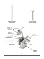
Fig. 1
Llave para quitar el tornillo
espiral del alimentador
Soporte de pared para
herramienta de corte
Asa de transporte
Controles
Tolva de
alimentación
Mortero
Conducto
Disco eyector
Eje de la cuchilla
Cámara de
cuchillas
Tornillo espiral del
alimentador
Placa empujadora
Asa de la placa
empujadora

– 6 –
FUNCIONAMIENTO
ADVERTENCIA
Cuchillas giratorias en el interior. Utilice siempre la placa empujadora. Mantenga las
manos fuera.
Es necesario el correcto ensamblaje del FP350, incluyendo la selección de las cuchillas adecuadas, para la
correctaoperacióndelprocesadordealimentos.RemítasealaGUÍADEHERRAMIENTASDECORTEpara
consultar el tamaño de las cuchillas y remítase a las instrucciones de operación adecuadas.
CONTROLES (FIG. 2)
START (Verde) — Pulse para arrancar.
STOP (Rojo) — Pulse para parar.
Los interruptores de enclavamiento impiden que el procesador de
alimentos funcione cuando el cilindro de alimentación está fuera
de posición o la placa empujadora está levantada por encima del
cilindro de alimentación. Si estas características no funcionan
segúnladescripción,póngaseencontactoconlaocinadeservicio
localdeHobart.
Durante el funcionamiento, cuando la placa empujadora se
eleva completamente por encima del cilindro de alimentación,
el procesador de alimentos se detiene y permite girar la placa
empujadora en sentido horario para cargarla. Para continuar con el
funcionamiento, gire la placa empujadora en sentido antihorario hasta
que quede directamente encima del cilindro de alimentación. Cuando la
placa empujadora comience a bajar hacia el cilindro de alimentación, el
procesador de alimentos se reiniciará — no es necesario que pulse el
interruptor verde START a menos que se haya pulsado STOP.
Pulse siempre el interruptor rojo STOP antes de cambiar las cuchillas o
de limpiar.
MONTAJE Y DESMONTAJE DE LA PLACA EMPUJADORA
1. Para colocar la placa empujadora, DEBE sujetarla con ambas
manos en las posiciones exactas que se muestran en la Fig. 3.
Sujétela con el asa de la placa empujadora hacia la izquierda de
la máquina (según mira al frente). Coloque el eje de la placa
empujadora contra el soporte del procesador de alimentos.
2. Empuje la placa empujadora hacia abajo en el eje con la mano
derecha hasta el tope (Fig. 4). El pasador del eje de la placa
empujadora debe deslizarse en la ranura del soporte.
3. Para retirar la placa empujadora, sujete el asa, levante la placa
empujadora y gírela hacia la izquierda para que el cilindro de
alimentación quede en posición abierta.
4. Sujete la placa empujadora con ambas manos (Fig. 3).
5. Gire la placa empujadora hasta que el pasador del eje salga de
la ranura del soporte. Tire de la placa empujadora hacia arriba y
hacia fuera con la mano derecha.
Fig. 2
Fig. 4
Fig. 3
EJE
SOPORTE

– 7 –
MONTAJE Y DESMONTAJE DE LAS HERRAMIENTAS DE CORTE
Cortar en rebanadas, rallar y cortar en juliana
1. Utilizando el asa de la placa empujadora,
levántela y gírela hacia la izquierda para que
el cilindro de alimentación quede en posición
abierta.
2. Libere el bloqueo del cilindro de alimentación
girando la palanca de bloqueo en sentido
antihorario. A continuación, gire el cilindro de
alimentación hacia la derecha.
3. Coloque el disco eyector (Fig. 5) sobre el eje
de la cuchilla. Presione el disco eyector hasta
el fondo y gírelo hasta que la placa quede en la
posición de bloqueo.
4. Seleccione la herramienta de corte apropiada
para el trabajo. Colóquela en el eje, girando
hasta que quede engranado.
5. Atornille el tornillo espiral del alimentador (Fig.
6) apretándolo a mano en sentido antihorario
en su posición en el centro de la herramienta
de corte.
6. Gire el cilindro de alimentación hacia la izquierda
y gire la palanca de bloqueo en sentido horario
hasta la posición de bloqueo.
Dados y papas fritas
1. Siga los pasos 1 a 3 anteriores.
2. Al cortar en dados, coloque un disco de cubeado adecuado (véase la Guía de herramientas de
corte) en la cámara de cuchillas y gire el disco de cubeado en sentido horario hasta el tope.
NOTA: Cuando corte papas fritas rectas, coloque el disco de papas fritas en la cámara de cuchillas y
gírelo en sentido horario hasta el tope.
3. Seleccione la herramienta de corte adecuada. Colóquela en el eje, girando hasta que quede
engranado.
4. Atornille a mano el tornillo espiral del alimentador en sentido antihorario en su posición en el centro
de la herramienta de corte.
5. Gire el cilindro de alimentación hacia la izquierda y gire la palanca de bloqueo en sentido horario
hasta la posición de bloqueo.
Si utiliza la combinación errónea de disco de cubeado y herramienta de rebanado (véase la Guía de
herramientas de corte), puede suceder lo siguiente:
• No se puede cerrar el cilindro de alimentación.
• El espacio entre el disco de cubeado y la herramienta de rebanado es demasiado grande y dará
como resultado malos cortes.
Fig. 5
Fig. 6

– 8 –
Retirar las herramientas de corte
1. Utilizando el asa de la placa empujadora, levántela
y gírela hacia la izquierda para que el cilindro de
alimentación quede en posición abierta.
2. Gire la palanca de bloqueo en sentido antihorario
y gire el cilindro de alimentación hacia la derecha.
3. Conlallave(Fig.7)suministrada,aojeeltornillo
espiral del alimentador en sentido horario.
4. Quite la(s) herramienta(s) de corte y el disco eyector.
USO DEL CILINDRO DE ALIMENTACIÓN
Después de levantar la placa empujadora, los productos preparados, como papas, zanahorias, cebollas,
lechugas, coles, etc., pueden colocarse en el cilindro de alimentación grande.
Cuando corte papas fritas con el cortador juliana, coloque/apile las papas contra la pared divisoria. Las
papas se pueden apilar para cortar varias a la vez. Para obtener resultados uniformes, apile el producto
contra la pared divisoria del cilindro de alimentación, en un solo grupo.
El cilindro de alimentación grande también se utiliza para cortar productos redondos como limones y
tomates. Coloque el producto contra la pared divisoria del cilindro de alimentación. Para obtener mejores
resultados, es aconsejable quitar la parte superior e inferior de productos redondos como limones, limas
o cebollas y colocarlos dentro del cilindro de alimentación en forma perpendicular al corte deseado.
Unalevepresiónsobrelaplacaempujadoraessucienteparaobtenerlosmejoresresultadosdecorte.
USO DEL TUBO DE ALIMENTACIÓN
Utilice el tubo de alimentación cuando corte elementos alargados como pepinos, puerros, etc.
Dado que el procesador de alimentos no se detiene cuando se retira el mortero para el tubo de alimentación,
puede utilizarlo para alimentar/cortar de forma continua. Utilice siempre el mortero para empujar los
alimentos a través del tubo de alimentación.
Fig. 7
La page charge ...
La page charge ...
La page charge ...
La page charge ...
La page charge ...
La page charge ...
La page charge ...
La page charge ...
La page charge ...
La page charge ...
La page charge ...
La page charge ...
La page charge ...
La page charge ...
La page charge ...
La page charge ...
-
 1
1
-
 2
2
-
 3
3
-
 4
4
-
 5
5
-
 6
6
-
 7
7
-
 8
8
-
 9
9
-
 10
10
-
 11
11
-
 12
12
-
 13
13
-
 14
14
-
 15
15
-
 16
16
-
 17
17
-
 18
18
-
 19
19
-
 20
20
-
 21
21
-
 22
22
-
 23
23
-
 24
24
-
 25
25
-
 26
26
-
 27
27
-
 28
28
-
 29
29
-
 30
30
-
 31
31
-
 32
32
-
 33
33
-
 34
34
-
 35
35
-
 36
36


