Hobart FP250 Manuel utilisateur

Taper
Manuel utilisateur

Ce manuel convient également à

701 S. RIDGE AVENUE
TROY, OHIO 45373
937 332-3000
www.hobartcorp.com FORM 48161 Rev. A (October 2023)
FP150 & FP250 FOOD PROCESSORS
MODEL
FP150 ML-104600
FP250 ML-136140
FP250 ML-136158
FP250
FP150
– 2 –
TABLE OF CONTENTS
GENERAL ............................................................................................................................................. 3
INSTALLATION ................................................................................................................................... 4
Unpacking ........................................................................................................................................ 4
Moving ............................................................................................................................................. 4
Location ........................................................................................................................................... 4
Wall Rack Installation ...................................................................................................................... 4
Electrical Connections ..................................................................................................................... 4
Installing the Pusher Plate ............................................................................................................... 5
Checking the Safety Interlocks ........................................................................................................ 5
Installing the Cutting Plate ............................................................................................................... 6
Removing the Cutting Plate ............................................................................................................. 6
OPERATION ........................................................................................................................................ 7
Controls ........................................................................................................................................... 7
Feed Hopper .................................................................................................................................... 7
Operating with the Feed Hopper ..................................................................................................... 8
Feed Tube ....................................................................................................................................... 8
Operating with the Feed Tube ......................................................................................................... 8
Cutting Tool Guide ........................................................................................................................... 9
CLEANING ......................................................................................................................................... 10
Immediately After Use ................................................................................................................... 10
MAINTENANCE ..................................................................................................................................11
Weekly Check ................................................................................................................................. 11
Transmission ..................................................................................................................................11
Cutting Plates .................................................................................................................................11
Service ............................................................................................................................................ 11
TROUBLESHOOTING ...................................................................................................................... 12
Service ........................................................................................................................................... 12
© HOBART, 2023
– 3 –
Installation, Operation and Care of
FP150 and FP250 Food Processors
SAVE THESE INSTRUCTIONS
GENERAL
The model FP150 and FP250 Food Processor can process vegetables, fruit, bread, cheese and nuts. Its
sleek, angled design allows food to be loaded easily into either a narrow feed tube or a full size feed hopper.
Various cutting plates can be used to slice, dice, grate, shred, julienne and make regular-cut and crinkle-
cut potato chips and french fries. In addition, the pusher plate has an assisting mechanism that reduces
the pressure needed to push food onto the cutting plates.
The Food Processor also has two built-in safety interlocks. An automatic start-stop interlock stops the food
processor when the pusher plate is raised and swung away from the feed hopper and restarts the food
processor when the pusher plate is moved back over and into the hopper. The other interlock keeps the
food processor turned o until the feed hopper is placed in the correct position.
To save space, wall-mounted storage racks are available. Each rack can hold three cutting plates.
FP150 FP250
– 4 –
INSTALLATION
UNPACKING
The food processor was inspected before leaving the factory. The carrier assumes full responsibility for safe
delivery upon acceptance of the shipment. Check for possible shipping damage immediately after receipt.
If the food processor is found to be damaged, complete the following steps:
1. Carrier must be notied within ve business days of receipt.
2. Carrier’s local terminal must be notied immediately upon discovery (note the time, date, and who
was spoken to), and follow up and conrm with written or electronic communication.
3. All original packing materials must be kept for inspection purposes.
4. The food processor cannot have been moved, installed, or modied.
5. Notify Hobart customer care at (800) 333-7447.
Prior to installing the food processor, verify that the electrical service agrees with the specications on the
machine data plate, which is located on the back of the machine.
Check that the cutting tools are in good condition and are sharp.
MOVING
To lift and move the food processor, grasp the handle at the back of the base with one
hand and grasp the discharge chute on the front with the other hand.
LOCATION
The food processor should be placed on a sturdy, level surface. There should be
adequate space around the food processor for the user to operate the controls and to
place and remove pans and bowls under the discharge chute.
WALL RACK INSTALLATION
The wall rack has space for three cutting tools. It is easily mounted on the wall and
provides a quick overview of cutting tools and saves space. To install, ensure wall rack
is positioned longways (Fig. 1). Top of wall rack is end with the screw hole on the end.
ELECTRICAL CONNECTIONS
The electrical cord on this machine is equipped with a three-pronged grounding
plug which must be connected to a properly grounded receptacle. If the receptacle is not the
proper grounding type, contact an electrician. Do not remove the grounding prong from the plug.
Fig. 1
– 5 –
INSTALLING THE PUSHER PLATE
Grasp the pusher plate handle with both hands and place the
pusher plate shaft (Fig. 2) into the hole on the food processor.
NOTE: Pusher plate and handle must be at the 10 o'clock
position, (while looking down at the feed hopper) before it can
be fully inserted into hole.
Push the pusher plate shaft all the way to the bottom.
CHECKING THE SAFETY INTERLOCKS
Check the following before you install the cutting plate or ejector plate:
1. Press the ON button.
2. Lift the pusher plate, with the pusher plate handle, and move the plate to the left. Make sure the food
processor stops running.
3. Move the pusher plate to the right and lower the pusher plate. With the feed hopper in operating
position, make sure the food processor starts.
4. Make sure the food processor does not turn on when the pusher plate is lowered and the feed hopper
is removed.
If the food processor fails any of these tests, contact your local Hobart service oce.
Fig. 2
– 6 –
INSTALLING THE CUTTING PLATE
1. Lift the pusher plate handle and move it to the left, away
from the feed hopper (Fig. 3).
2. Turn the locking knob counterclockwise to unlock the
feed hopper (Fig. 3).
3. Raise the feed hopper (Fig. 3).
4. Center the ejector plate on the shaft and, with the slots
in the ejector plate aligned with the pins in the coupling,
push the ejector plate down to the bottom of the shaft
and onto its coupling (Fig. 4). Turn counterclockwise to
lock.
5. If dicing or chopping insert a dicing grid, and turn it until the holding pin ts into the notch (Fig. 4).
6. Avoid contact with sharp knife on the cutting plate and put the desired cutting plate on the shaft
and turn the cutting plate until it falls onto its coupling (Fig. 5). Turn counterclockwise to lock.
7. Put the decoring screw on the shaft. Turn it counterclockwise to tighten (Fig. 5).
NOTE: Decoring screw uses left-hand threads.
8. Move the feed hopper back into position (Fig. 3).
9. Turn the locking knob clockwise to lock the feed hopper in place.
REMOVING THE CUTTING PLATE
1. Lift the pusher plate handle and move it to the left, away
from the feed hopper (Fig. 3).
2. Turn the locking knob counterclockwise to unlock the
feed hopper.
3. Raise the feed hopper.
4. Remove the decoring screw by turning it clockwise with
the wrench (Fig. 6).
5. Remove the cutting plate, dicing grid (if used) and
ejector plate from the food processor.
Fig. 3
Fig. 4 Fig. 5
Fig. 6
– 7 –
OPERATION
Rotating knives inside. Always use the pusher plate. Keep hands out.
Do not put meat, dough or frozen foods in the food processor. Remove all hard parts that can
damage the cutting plate blades, such as apple and pineapple stems, mango pits and brous cores.
CONTROLS
The pusher plate presses food items against the cutting
blades. It is controlled by a large pusher plate handle that
wraps around the feed hopper (Fig. 7).
The food processor can be started by pressing the green ON
button and stopped by pressing the red OFF button (Fig. 7).
The ON button needs to be pressed only if the OFF button is
pressed or after connecting the electrical power cord.
The food processor restarts automatically when the pusher
plate is centered over the feed hopper and lowered. It stops
automatically when the pusher plate is raised and moved to
the left of the feed hopper or when the feed hopper itself is
raised. The pusher plate must be turned to the left to load
food into the feed hopper.
Be sure to press the OFF button and unplug the food processor power cord before cleaning or changing
the cutting plates.
FEED HOPPER
The full-size feed hopper processes large roundlike items such
as loaves of bread, heads of lettuce, pineapple, honeydew and
cabbage. In addition, small round items such as tomatoes,
potatoes and beets can be stacked against an inner support
wall (Fig. 8) inside the hopper.
Fig. 7
Fig. 8
– 8 –
OPERATING WITH THE FEED HOPPER
1. Raise the pusher plate and move it to the left.
2. Put produce into the feed hopper (Fig. 9).
3. Press the green ON button.
4. Move the pusher plate to the right and lower it into the feed
hopper (Fig. 7). The food processor will start when the pusher
plate enters the feed hopper.
5. Press down on the pusher plate handle with light pressure.
NOTE: Best product quality is achieved when only light pressure
is used to keep the product in contact with the cutting plate.
FEED TUBE
The feed tube (Fig. 10) processes long and thin items, such as carrots, cucumbers, celery and scallions.
It can also be loaded with small, odd-shaped items, such as mushrooms, shallots and garlic cloves. The
feed tube pusher (Fig. 10) sits in the feed tube when not in use, doubling as a cover. Removing the feed
tube pusher does not stop the food processor from running.
OPERATING WITH THE FEED TUBE
1. Position the pusher plate over the feed hopper and lower it the bottom.
2. Turn the feed tube pusher to unlatch it; remove the pusher (Fig. 10).
3. Put the food item into the feed tube (Fig. 11).
4. Put the feed tube pusher on top of the food item (Fig. 11).
5. Press the ON button.
6. Press down on the feed tube pusher with light pressure.
NOTE: Best product quality is achieved when only light pressure is used to keep the product in contact
with the cutting plate.
Fig. 9
Fig. 10 Fig. 11
– 9 –
CUTTING TOOL GUIDE
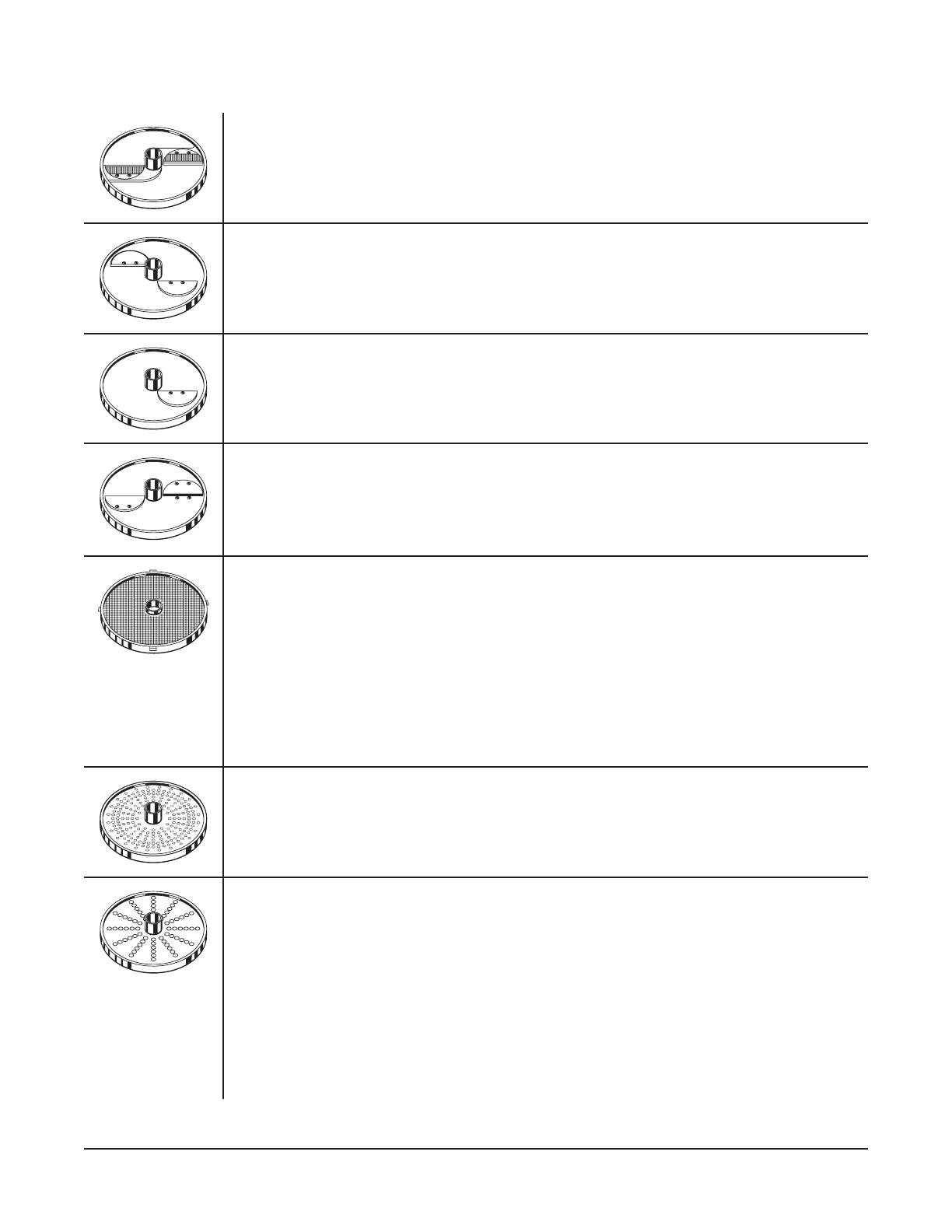
Crimping Slicer — 3/16" (4.5 MM)
For ripple slicing of root vegetables.
Fine Slicer (2 Blade) — 1/16" (1.5 MM)
For slicing rm or fragile products. Also for use with 9/32" dicing plate. Makes very thin slices of
pepperoni, mushrooms, cabbage, potatoes, cucumbers and radishes.
Fine Slicer (1 Blade) — 5/32" (4 MM), 9/16" (14 MM), 1/8" (3 MM), 7/32" (6 MM), 3/8" (10 MM)
Use is same as 2-blade ne slicer. Also slices soft and/or juicy products such as tomato,
lemon and banana. Shreds lettuce. Dices in combination with 5/32" dicing grid. Chops onion in
combination with 3/8" dicing grid.
Julienne Cutter —
3/32" (2 MM) — Makes various salad toppings.
3/16" (4.5 MM) — Makes shoestring French fries.
5/16" (8 MM) — Makes French fries.
Dicing Grid — Dices in combination with dicing cutter or ne cut slicer. The dicer grid dimension
must be equal to, or larger than, the slicer dimension.
9/32" (7.5 MM) (use with 7/32" or smaller Slicer) — For thin diced vegetables (carrots,
celery, onions, potatoes and vegetables for soup).
3/8" (10 MM) (use with 3/8" or smaller Slicer) — Good for dicing rm chilled tomatoes.
3/4" (20 MM) (use only with 9/16" Slicer) — Prepares tomatoes, potatoes for home fries
or potato salad and dices apples or melon.
5/8" (15 MM) (use with 3/8" or smaller Slicer) — Dices tomatoes, apples, melon and other
fruits for salads, pies or other uses.
Grater — Fine
Makes grated Parmesan or Romano cheese (hard cheese only).
Shredder — Shredder plates are used to process cheese for toppings and salad bar items,
cabbage for coleslaw, potatoes for hash browns or potato pancakes.
1/16" (1.5 MM) — Makes extra  ne shredded cheese for sandwich topping or other uses.
3/32" (2 MM) — Makes ne breadcrumbs and cracker crumbs for use in cooking. Use when
machine and product are dry.
1/8" (3 MM) — Medium shredder for various uses.
3/16" (4.5 MM) — Makes pizza toppings and salad bar items.
5/16" (8 MM) — Shreds cabbage and soft pizza cheese.
7/32" (6 MM) — Shreds carrot, dry bread, almonds, nuts, and soft pizza cheese.
A wall rack is available to hang the cutting tools for easy access of the operator and to protect sharpness of the blades.
– 10 –
CLEANING
Turn the machine o and unplug the electrical cord before you begin any cleaning
procedure.
Do not clean stainless steel with bleach-containing cleansers like automatic dishwashing
detergent: Bleach can corrode stainless steel. Do not clean the aluminum parts with high-alkaline detergents
like automatic dishwashing detergent or with hot water: Black aluminum oxide can form. Removable parts
should be handwashed in a three-part sink and should not be put into the dishwasher with the exception
of cutting tools and the decoring screw.
Do not spray the food processor with a spray bottle or hose, and do not scrape with metal
objects that can scratch the metal surfaces.
IMMEDIATELY AFTER USE
Removable parts must be cleaned with warm water and soap. Thoroughly rinse and dry with a soft, clean
cloth:
1. Remove the feed tube pusher.
2. Lift the pusher plate and move it to the left, lift and remove.
3. Turn the locking knob counterclockwise to unlock the feed hopper.
4. Raise the feed hopper and slide it o its hinge pins.
5. Unthread the decoring screw clockwise with the wrench and remove it.
6. Remove the cutting plate and, if used, the dicing grid. Use the brush to push remaining food through
the dicing grid.
7. Remove the ejector plate.
8. Remove food waste from discharge chute and cutting plate chamber.
9. Use a clean cloth with warm soapy water to wipe the cutting plate chamber, discharge chute and
motor housing.
NOTE: Use caution to prevent liquid from entering pusher plate mounting hole.
10. Use a clean cloth with clean water to rinse the cutting plate chamber, discharge chute and motor
housing.
NOTE: Use caution to prevent liquid from entering pusher plate mounting hole.
11. Wipe the cutting plate blades dry with a clean cloth and put the cutting plates on the wall racks.
12. Put the ejector plate on the shaft until it drops onto its coupling and turn it counterclockwise to
lock.
13. Put the decoring screw on the shaft and turn it counterclockwise, hand-tighten only for storage.
14. Put the feed hopper on its hinge pins and lower it into operating position.
15. Return the pusher plate and feed tube pusher to their operating positions.
– 11 –
MAINTENANCE
WEEKLY CHECK
1. With the power cord connected to the outlet, test the safety interlock switches. See Checking the
Safety Mechanisms.
2. The remaining checks must be performed with the power cord unplugged from the outlet.
Unplug the machine power cord before you do the maintenance procedures listed
below.
3. Inspect the power cord and make sure it is in good shape. Look for cuts, fraying or cracking.
4. Make sure the pusher plate shaft moves freely. If it does not, clean and dry it and lubricate with
several drops of mineral oil.
5. Make sure the cutting plate blades are sharp. If not, have them sharpened or the cutting plate
replaced.
TRANSMISSION
The planetary gear transmission is maintenance free.
CUTTING PLATES
Depending on usage, dicing grids become dull from wear with an average life expectancy from
8–18 months. Dicing grids cannot be resharpened and are therefore expendable. Replacement
dicing grids are available from your local Hobart Service oce.
SERVICE
If service is required on this equipment, return it to your local Hobart Service Center. For an authorized
Hobart Service Center, call 1-888-4-HOBART.
– 12 –
TROUBLESHOOTING
Fault Possible Cause Remedy
Food processor does not
start.
Pusher plate is raised. Move pusher plate over feed
hopper and lower it.
Feed hopper is not in operating
position.
Put feed hopper in operating
position.
Tripped branch circuit protector. Check premises fuse or circuit
breaker panel for blown fuse or
tripped circuit breaker.
Food processor stops while
operating and does not
restart.
Pusher plate is raised and
moved to the left.
Move pusher plate over feed
hopper and lower it.
Tripped branch circuit protector. Check premises fuse or circuit
breaker panel for blown fuse or
tripped circuit breaker.
Overheated motor. Let the motor cool until it
automatically restarts.
Food is cut poorly or slowly Wrong cutting plates used. See Cutting Plate Guide.
Cutting plates are dull or
knicked.
Sharpen or replace cutting plates.
Pressing pusher plate handle
too hard.
Press down on the product lightly.
Cutting plate cannot be
removed
Clogged with built-up food
particles or ejector plate not
used.
Using protective leather gloves,
rotate the cutting plate clockwise to
release.
Decoring screw cannot be
removed.
Clogged with built-up food
particles.
Turning the wrong direction.
Turn the decoring screw clockwise
with the wrench (Fig. 5).
Scraping noise. Dicing grid not down in its
coupling.
Remove dicing grid, clean any
debris on walls and ledge of cutting
plate chamber and reinstall grid.
Decoring screw not installed. Install the decoring screw.
SERVICE
Contact your local Hobart Service Oce for any repairs or adjustments needed on this equipment. Long-
term service contracts are available on this and other Hobart products.
FORM 48161 Rev. A (October 2023) PRINTED IN U.S.A.
701 S. RIDGE AVENUE
TROY, OHIO 45373
937 332-3000
www.hobartcorp.com FORMULARIO 48161 Rev. A (octubre de 2023)
PROCESADORES DE ALIMENTOS
FP150 Y FP250
MODELO
FP150 ML-104600
FP250 ML-136140
FP250 ML-136158
FP250
FP150
– 2 –
TABLA DE CONTENIDO
GENERAL ............................................................................................................................................. 3
INSTALACIÓN .................................................................................................................................... 4
Desembalaje .................................................................................................................................... 4
Traslado ........................................................................................................................................... 4
Ubicación ......................................................................................................................................... 4
Instalación del bastidor de pared ..................................................................................................... 4
Conexiones eléctricas ..................................................................................................................... 4
Instalación de la placa empujadora ................................................................................................. 5
Comprobación de los enclavamientos de seguridad ....................................................................... 5
Instalación del disco de corte .......................................................................................................... 6
Cómo retirar el disco de corte ......................................................................................................... 6
OPERACIÓN ........................................................................................................................................ 7
Controles ......................................................................................................................................... 7
Tolva de alimentación ...................................................................................................................... 7
Operar con la tolva de alimentación ................................................................................................ 8
Tubo de alimentación ...................................................................................................................... 8
Operar con el tubo de alimentación ................................................................................................. 8
Guía de herramientas de corte ........................................................................................................ 9
LIMPIEZA ........................................................................................................................................... 10
Inmediatamente después del uso .................................................................................................. 10
MANTENIMIENTO ..............................................................................................................................11
Control semanal .............................................................................................................................11
Transmisión ....................................................................................................................................11
Discos de corte ...............................................................................................................................11
Servicio ...........................................................................................................................................11
SOLUCIÓN DE PROBLEMAS .......................................................................................................... 12
Servicio .......................................................................................................................................... 12
© HOBART, 2023
– 3 –
Instalación, funcionamiento y cuidado de los
procesadores de alimentos FP150 y FP250
CONSERVE ESTAS INSTRUCCIONES
GENERAL
El procesador de alimentos Modelo FP150 y FP250 puede procesar verduras, frutas, pan, queso y frutos secos.
Su diseño elegante y anguloso permite cargar fácilmente los alimentos en un tubo de alimentación estrecho
o en una tolva de alimentación de tamaño completo.
Se pueden utilizar varios discos de corte para rebanar, cortar en cubos, rallar, desmenuzar, cortar en juliana,
y hacer papas fritas de corte regular y de corte ondulado. Además, la placa empujadora tiene un mecanismo
de ayuda que reduce la presión necesaria para empujar los alimentos hacia los discos de corte.
El procesador de alimentos también cuenta con dos enclavamientos de seguridad incorporados. Un enclavamiento
automático de arranque-parada detiene el procesador de alimentos cuando la placa empujadora se levanta y
se aleja de la tolva de alimentación, y vuelve a ponerlo en marcha cuando la placa empujadora se mueve de
nuevo hacia la tolva. El otro enclavamiento mantiene el procesador de alimentos apagado hasta que la tolva
de alimentación se coloca en la posición correcta.
Para ahorrar espacio, existen bastidores de almacenamiento montados en la pared. Cada bastidor puede
albergar tres discos de corte.
FP150 FP250
– 4 –
INSTALACIÓN
DESEMBALAJE
El procesador de alimentos fue inspeccionado antes de salir de fábrica. El transportista asume total
responsabilidad por la entrega segura una vez aceptado el cargamento. Compruebe que no haya daños al
cargamento inmediatamente después de recibirlo.
Si el procesador de alimentos está dañado, siga los siguientes pasos:
 1. Noticaraltransportistadentrodeloscincodíashábilessiguientesalafechaderecepción.
 2. Noticardeinmediatoalaterminallocaldeltransportistatraseldescubrimiento(anotarlahora,lafechay
lapersonaconquiensehabló)yhacerunseguimientoyenviarlaconrmaciónmediantecomunicaciones
escritas o electrónicas.
3. Conservar todos los materiales originales del embalaje por motivos de inspección.
 4. Elprocesadordealimentosnodebesermovido,instaladonimodicado.
 5. NoticaralServiciodeAtenciónalClientedeHobartal(800)333-7447.
Antes de instalar el procesador de alimentos, verique que el servicio eléctrico sea compatible con las
especicacionesdelaplacadedatosdelamáquina,queseencuentraenlaparteposteriordelamáquina.
Compruebequelasherramientasdecorteesténenbuenestadoyaladas.
TRASLADO
Para levantar y mover el procesador de alimentos, agarre el asa de la parte trasera de la
base con una mano y agarre el conducto de descarga de la parte delantera con la otra.
UBICACIÓN
Elprocesadordealimentosdebecolocarseenunasupercierobustaynivelada.Debe
haber un espacio adecuado alrededor del procesador de alimentos para que el usuario
pueda manejar los mandos y colocar y retirar las cacerolas y los cuencos bajo el conducto
de descarga.
INSTALACIÓN DEL BASTIDOR DE PARED
El bastidor de pared tiene espacio para tres herramientas de corte. Se monta fácilmente
en la pared, proporciona una rápida visión de las herramientas de corte y ahorra espacio.
Parainstalarlo,asegúresedequeelbastidordeparedestécolocadoalolargo(Fig.1).
Lapartesuperiordelbastidordeparedeselextremoconeloriciodeltornillo.
CONEXIONES ELÉCTRICAS
ADVERTENCIA
El cable eléctrico de esta máquina está equipado con un enchufe de conexión a tierra
con tres terminales que se deben conectar correctamente a una toma con conexión a tierra. Si la toma
de corriente no es la correcta, comuníquese con un electricista. No quite el terminal de conexión a
tierra del enchufe.
Fig. 1
– 5 –
INSTALACIÓN DE LA PLACA EMPUJADORA
Agarre el asa de la placa empujadora con ambas manos y
coloqueelejededichaplaca(Fig.2)eneloriciodelprocesador
de alimentos.
NOTA: La placa empujadora y el asa deben estar en posición de
las10enpunto(mirandohaciaabajoenlatolvadealimentación)
antesdequesepuedainsertarcompletamenteeneloricio.
Empuje el eje de la placa empujadora hasta el fondo.
COMPROBACIÓN DE LOS ENCLAVAMIENTOS DE SEGURIDAD
Compruebe lo siguiente antes de instalar el disco de corte o el disco eyector:
1. Pulse el botón ON.
2. Levante la placa empujadora con el asa de dicha placa, y mueva la placa hacia la izquierda. Asegúrese
de que el procesador de alimentos deje de funcionar.
3. Mueva la placa empujadora hacia la derecha y baje dicha placa. Con la tolva de alimentación en posición
de funcionamiento, asegúrese de que el procesador de alimentos se pone en marcha.
4. Asegúrese de que el procesador de alimentos no se encienda cuando se baja la placa empujadora y se
retira la tolva de alimentación.
Sielprocesadordealimentosnosuperaalgunadeestaspruebas,póngaseencontactoconsuocinade
serviciolocaldeHobart.
Fig. 2
EJE DE LA PLACA
EMPUJADORA
– 6 –
INSTALACIÓN DEL DISCO DE CORTE
1. Levante el asa de la placa empujadora y muévala hacia la
izquierda,alejándoladelatolvadealimentación(Fig.3).
2. Gire el pomo de bloqueo en sentido contrario a las agujas
delrelojparadesbloquearlatolvadealimentación(Fig.3).
 3.Elevelatolvadealimentación(Fig.3).
4. Centre el disco eyector en el eje y, con las ranuras del disco
eyector alineadas con los pasadores del acoplamiento,
empuje el disco eyector hasta el fondo del eje y sobre su
acoplamiento(Fig.4).Gireensentidocontrarioalasagujas
del reloj para bloquear.
5. Si va a cortar en cubos o en trozos, inserte un disco de
cubeado para cortar en cubos y gírelo hasta que el pasador
deretenciónencajeenlamuesca(Fig.4).
6. Evite el contacto con la cuchilla alada en el disco de corte, coloque el disco de corte que desee
enelejeygírelohastaquecaigasobresuacoplamiento(Fig.5).Gireensentidocontrarioalasagujas
del reloj para bloquear.
7. Coloque el tornillo espiral del alimentador en el eje. Gire en sentido contrario a las agujas del reloj para
apretar(Fig.5).
NOTA: El tornillo espiral del alimentador utiliza roscas a la izquierda.
 8.Vuelvaacolocarlatolvadealimentaciónensuposición(Fig.3).
9. Gire el pomo de bloqueo en el sentido de las agujas del reloj para bloquear la tolva de alimentación en
su lugar.
CÓMO RETIRAR EL DISCO DE CORTE
1. Levante el asa de la placa empujadora y muévala hacia la
izquierda,alejándoladelatolvadealimentación(Fig.3).
2. Gire el pomo de bloqueo en sentido contrario a las agujas
del reloj para desbloquear la tolva de alimentación.
3. Eleve la tolva de alimentación.
4. Retire el tornillo espiral del alimentador girándolo con la
llaveenelsentidodelasagujasdelreloj(Fig.6).
 5.Retireeldiscodecorte,eldiscodecubeado(siseutiliza)
y el disco eyector del procesador de alimentos.
Fig. 3
ASA DE LA PLACA
EMPUJADORA
POMO DE
BLOQUEO
TOLVA DE
ALIMEN-
TACIÓN
DISCO DE
CUBEADO EJE
DISCO
EYECTOR
Fig. 4
TORNILLO
ESPIRAL DEL
ALIMENTADOR
DISCO DE
CORTE
Fig. 5
Fig. 6
TORNILLO
ESPIRAL DEL
ALIMENTADOR
LLAVE
– 7 –
OPERACIÓN
ADVERTENCIA
Cuchillas giratorias en el interior. Utilice siempre la placa empujadora. Mantenga las
manos fuera.
AVISO
No ponga carne, masa o alimentos congelados en el procesador de alimentos. Retire todas las
partes duras que puedan dañar las cuchillas del disco de corte, como los tallos de las manzanas y las piñas,
loshuesosdelosmangosylosnúcleosbrosos.
CONTROLES
La placa empujadora presiona los alimentos contra las cuchillas
de corte. Se controla mediante el asa de gran tamaño de la
placaempujadoraqueenvuelvelatolvadealimentación(Fig.7).
El procesador de alimentos puede ponerse en marcha pulsando
elbotónverdeONydetenersepulsandoelbotónrojoOFF(Fig.
7). El botón ON solo debe pulsarse si se pulsa el botón OFF o
después de conectar el cable de alimentación eléctrica.
El procesador de alimentos se reinicia automáticamente cuando
la placa empujadora se centra sobre la tolva de alimentación
y se baja. Se detiene automáticamente cuando la placa
empujadora se eleva y se desplaza hacia la izquierda de la
tolva de alimentación, o cuando la propia tolva de alimentación
se eleva. La placa empujadora debe girarse hacia la izquierda
para cargar los alimentos en la tolva de alimentación.
Asegúrese de pulsar el botón OFF y desenchufar el cable de alimentación del procesador de alimentos antes
de limpiar o cambiar los discos de corte.
TOLVA DE ALIMENTACIÓN
La tolva de alimentación de tamaño completo procesa productos
grandes de forma redonda, como barras de pan, cabezas de
lechuga, piña, melaza y col. Además, los artículos redondos
pequeños, como los tomates, las papas y las remolachas,
puedenapilarsecontraunapareddesoporteinterior(Fig.8)
dentro de la tolva.
Fig. 7
ASA DE
LA PLACA
EMPUJADORA
TOLVA DE
ALIMEN-
TACIÓN
APAGADO
ENCENDIDO
PARED DE
SOPORTE
INTERNA
Fig. 8
– 8 –
OPERAR CON LA TOLVA DE ALIMENTACIÓN
1. Levante la placa empujadora y muévala hacia la izquierda.
 2.Coloqueelproductoenlatolvadealimentación(Fig.9).
3. Pulse el botón verde ON.
4. Mueva la placa empujadora hacia la derecha y bájela a la tolva
dealimentación(Fig.7).Elprocesadordealimentossepondrá
en marcha cuando la placa empujadora entre en la tolva de
alimentación.
5. Presiona sobre el asa de la placa empujadora sin una fuerza
excesiva.
NOTA: La mejor calidad del producto se consigue cuando solo se
utiliza una ligera presión para mantener el producto en contacto con
el disco de corte.
TUBO DE ALIMENTACIÓN
Eltubodealimentación(Fig.10)procesaproductoslargosydelgados,comozanahorias,pepinos,apioy
cebollas. También se puede cargar con productos pequeños y de forma irregular, como champiñones, chalotas
ydientesdeajo.Elempujadordeltubodealimentación(Fig.10)seasientaendichotubocuandonose
utiliza, haciendo las veces de tapa. Retirar el empujador del tubo de alimentación no hace que el procesador
de alimentos deje de funcionar.
OPERAR CON EL TUBO DE ALIMENTACIÓN
1. Coloque la placa empujadora sobre la tolva de alimentación y bájela el fondo.
 2.Gireelempujadordeltubodealimentaciónparadesengancharlo;retireelempujador(Fig.10).
 3.Introduzcaelalimentoeneltubodealimentación(Fig.11).
 4.Coloqueelempujadordeltubodealimentaciónsobreelalimento(Fig.11).
5. Pulse el botón ON.
6. Presione sobre el empujador del tubo de alimentación sin una fuerza excesiva.
NOTA: La mejor calidad del producto se consigue cuando solo se utiliza una ligera presión para mantener el
producto en contacto con el disco de corte.
Fig. 9
Fig. 10 Fig. 11
  • Page 1 1
  • Page 2 2
  • Page 3 3
  • Page 4 4
  • Page 5 5
  • Page 6 6
  • Page 7 7
  • Page 8 8
  • Page 9 9
  • Page 10 10
  • Page 11 11
  • Page 12 12
  • Page 13 13
  • Page 14 14
  • Page 15 15
  • Page 16 16
  • Page 17 17
  • Page 18 18
  • Page 19 19
  • Page 20 20
  • Page 21 21
  • Page 22 22
  • Page 23 23
  • Page 24 24
  • Page 25 25
  • Page 26 26
  • Page 27 27
  • Page 28 28
  • Page 29 29
  • Page 30 30
  • Page 31 31
  • Page 32 32
  • Page 33 33
  • Page 34 34
  • Page 35 35
  • Page 36 36

Hobart FP250 Manuel utilisateur

Taper
Manuel utilisateur
Ce manuel convient également à

dans d''autres langues