Robert Juliat ZEP2 360LF2 Manuel utilisateur
- Catégorie
- Stroboscopes
- Taper
- Manuel utilisateur
Ce manuel convient également à

360LF
Version V1
360LF & 360CLF
VARIABLE BEAM ANGLE LED WASH LIGHT /
PROJECTEUR A LED TYPE WASH
MANUAL / POLE OPERATED
COMMANDES MANUELLES / COMMANDES A PERCHE
SINGLE LENS LUMINAIRES /
VALIDATION: 18/05/17
DN41085500-A
Manual / Manuel
Robert Juliat S.A.S. 32, rue de Beaumont, F 60530 Fresnoy-en-Thelle - phone : +33 (0)3 44 26 51 89 - fax : +33 (0)3 44 26 90 79 - [email protected]
www.robertjuliat.com

EN
Robert Juliat reserve the right to change
or alter any of the items detailed on this page,
to increase or improve manufacturing techniques without prior notice.
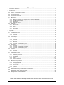
Summary :
1!User’s instructions .............................................................................................................................................. 1!
2!Presentation ....................................................................................................................................................... 2!
2.1!360LF – Manually operated ........................................................................................................................ 2!
2.2!360LF – Pole operated ............................................................................................................................... 2!
2.3!Identification plate ....................................................................................................................................... 3!
2.4!Accessories included .................................................................................................................................. 3!
2.5!Optional accessories ................................................................................................................................... 4!
3!Set-up ................................................................................................................................................................. 5!
3.1!Mechanics ................................................................................................................................................... 5!
3.1.1!Operating positions .............................................................................................................................. 5!
3.1.2!Minimum distance between a flammable material and the lighting unit .............................................. 5!
3.1.3!Operating conditions ............................................................................................................................ 5!
3.1.4!Hanging ............................................................................................................................................... 5!
3.1.5!Safety cable ......................................................................................................................................... 6!
3.2!Electrical ..................................................................................................................................................... 6!
3.2.1!LED source .......................................................................................................................................... 6!
3.2.2!Power .................................................................................................................................................. 6!
3.2.3!DATA ................................................................................................................................................... 7!
3.3!Accessories ................................................................................................................................................. 9!
3.3.1!Gel frame ............................................................................................................................................. 9!
3.3.2!Barndoors .......................................................................................................................................... 10!
4!Operation .......................................................................................................................................................... 11!
4.1!Light intensity ............................................................................................................................................ 11!
4.1.1!Range ................................................................................................................................................ 11!
4.1.2!Control ............................................................................................................................................... 11!
4.2!Strobe ....................................................................................................................................................... 12!
4.2.1!Range ................................................................................................................................................ 12!
4.2.2!Control ............................................................................................................................................... 12!
4.3!Beam size adjustment ............................................................................................................................... 13!
4.3.1!Range ................................................................................................................................................ 13!
4.3.2!Control – Manually operated ............................................................................................................. 14!
4.3.3!Control – Pole operated ..................................................................................................................... 14!
4.4!Orientation ................................................................................................................................................ 15!
4.4.1!Range ................................................................................................................................................ 15!
4.4.2!Control – Manually operated ............................................................................................................. 15!
4.4.3!Control – Manually operated ............................................................................................................. 15!
4.5!Colour ....................................................................................................................................................... 16!
4.6!Beam shaping with barndoors option ........................................................................................................ 17!
4.6.1!Range ................................................................................................................................................ 17!
4.6.2!Control ............................................................................................................................................... 17!
4.7!Control board ............................................................................................................................................ 18!
4.7.1!Display and Controls ......................................................................................................................... 18!
4.7.2!Menus and parameters ...................................................................................................................... 18!
4.7.4!Reset ................................................................................................................................................. 19!
4.7.5!Feedback information ........................................................................................................................ 19!
5!Service ............................................................................................................................................................. 22!
5.1!Preventive maintenance ........................................................................................................................... 22!
5.1.1!Frequency .......................................................................................................................................... 22!
5.1.2!General cleaning ............................................................................................................................... 22!
5.1.3!General visual check ......................................................................................................................... 19!
5.1.4!LED source ........................................................................................................................................ 20!
5.1.5!Optics ................................................................................................................................................ 20!
5.2!Analysis ..................................................................................................................................................... 20!
5.3!LED reaction according to LED temperature ............................................................................................ 20!
5.4!Thermal protection .................................................................................................................................... 20!
5.5!Adjusting the maximum light output level .................................................................................................. 20!
5.6!Exploded view / Spare parts list ................................................................................................................ 20!
6! Troubleshooting ................................................................................................................................................ 21!
4.7.3!DMX Chart........................................................................................................................................... 18!

EN
- 1 -
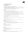
1 User’s instructions
GENERAL INSTRUCTIONS
1. Not for residential use.
2. These fixtures must only be serviced by a qualified technician.
3. In addition to the instructions indicated on this page, relevant health and safety requirements of the appropriate EU
Directives must be adhered to at all times.
4. This fixture is in compliance with section 17 - Lighting appliance for theatre stages, television, cinema and photograph
studios. Standards NF EN 60598-1 and NF EN 60598-2-17.
5. This fixture is rated as IP20, and is for indoor use only.
FIXTURE
6. Ensure fixture is correctly mounted on an appropriate support.
7. Protection screens and lenses must be replaced in the event of any damage, such as cracks or deep scratches, since
these might reduce performance.
8. When hung or flown the fixture must be secured by an additional hanging accessory (such as a safety cable or bond) of
suitable length.
9. Safety bonds or cables must be securely attached to the back of the fixture and be as short as possible, or rolled up as
necessary, to minimise travel distance should the fixture be dislodged.
10. Movable accessories (scroller, etc.) must also be secured with a suitable safety cable or bond at the front of the fixture.
11. The combined weight of both the fixture and the accessories must be considered when choosing the load-bearing
capability of safety cable or bond.
12. Do not open lighting fixture when the source is on.
13. WARNING: LED source become hot during use. Allow fixture to cool before servicing.
14. Do not tamper with design of fixture nor any of its safety features.
15. Tighten electrical mains cable connections regularly and replace with one of identical specification if damaged.
16. Use only with recommended power input.
17. Do not orientate the fixture towards a source of light (sun, fixture), in particular for LED versions.
VENTILATION
18. Keep well away from flammable material.
19. Not for outdoor use. Do not cover. Do not permit fixture to get wet.
20. To avoid overheating, do not obstruct air vents.
21. Ensure any cooling fans are in correct working order. If fans are not working, turn fixture off immediately and service as
necessary.
CLEANING
22. Do not touch LED source with fingers.
23. Clean all optical parts with alcohol-based cleaner.
24. Clean all filters regularly.
POWER SUPPLY
25. Disconnect from the mains before servicing.
26. Mains connection only. Do not connect to "electronic output" such as dimmer.
27. Not for outdoor use. Do not cover.
PLEASE NOTE
These products have been built to conform to European standards relating to professional lighting equipment. Any modification
made to our products will void the manufacturers' warranty.

EN
- 2 -
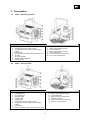
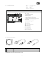
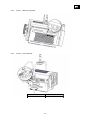
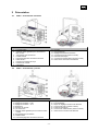
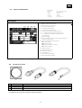
2 Presentation
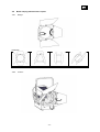
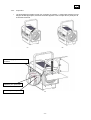
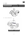
2.1 360LF – Manually operated
Functions :
1. Hanging yoke
2. Accessories and colour filter runners
3. Accessories and colour filter runners locking
system
4. Fresnel lens
5. Front accessories safety cable attachment point
6. Tilt index
7. Tilt locking handle
8. Control board and display
9. ON/OFF Switch
10. Handle
11. Safety cable attachment point
12. Focus adjustment
13. Data connectors (IN and OUT)
14. Thermal Protection
15. Power connectors (IN and OUT)
16. Front focus internal index
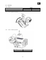
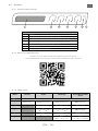
2.2 360LF – Pole operated
Functions :
1. Focus adjustment
2. PAN adjustment
3. TILT adjustment
4. ON/OFF switch
5. Control board
6. Hanging yoke
7. Accessories and colour filter runners
8. Accessories and colour filter runners locking
system
9. Fresnel lens
10. Front accessories safety cable attachment point
11. Handle
12. Safety cable attachment point
13. Focus adjustment
14. Data connectors (IN and OUT)
15. Thermal Protection
16. Power connectors (IN and OUT)
17. Front focus internal index

EN
- 3 -
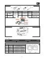
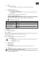
2.3 Identification plate
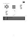
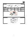
2.4 Accessories included
Reference Description
1 PF1000M2 215 x 215mm filter holder
2* FJUC000112 Power cord with CEE7/7 connector
3* FJUC000113 UL/CSA power cord without connector
(*) Supplied with cord 2 or 3 depending on the country
! " #
Description
Units :
- Dimensions
- Weight
- Intensity
- Voltage
- Frequency
- Temperature
= metre (m) millimetre (mm).
= kilogram (kg).
= Ampere (A).
= Volt (V).
= Hertz (Hz).
= degree Celsius (°C).
1. MOD. : Model
2. VERS. : Version
3. U : Nominal voltage input (V)
4. I : Nominal intensity (A)
5. P : Maximum power input (W)
6. IP : International Protection Rating
7. t°a : Maximum ambiant temperature (°C)
8. t°c : Maximum external temperature of the unit (°C)
9. Net weight (kg)
10. Minimum distance between a flammable
material and the lighting unit (m)
11. Colour temperature version :
CW = Cool White
WW = Warm White
NDW = Neutral Daylight White
VW = Variable White
12. Serial number
13. Replace broken glass
14. Class 1 product label
15. Read manual first label
16. European conformity label
17. WEEE directive label
1 2
3 4
5 6
7 8
9
10
11
12
13
14 15 16 17

EN
- 4 -
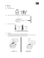
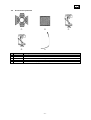
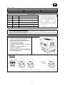
2.5 Optional accessories
!
"
#
$
%
Reference
Description
1
CF1000
4 Rotating leaves on a rotating barndoor (without safety cable)
2
G1000
215 x 215 mm safety grid
3
876
40 x 10 mm with 28 mm screw clamp for Ø 35 to 50 mm pipes
4
880
40 x 10 mm with 28 mm screw clamp for Ø 50 to 63 mm pipes
5
CS2
Safety cable (length = 600 mm)

EN
- 5 -
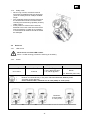
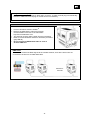
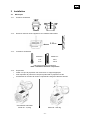
3 Set-up
3.1 Mechanics
3.1.1 Operating positions
3.1.2 Minimum distance between a flammable material and the lighting unit
3.1.3 Operating conditions
Minimum :
5°C
41°F
Maximum :
40°C
104°F
Indice de Protection international:
IP20 – Utilisation intérieure uniquement
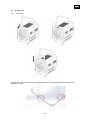
3.1.4 Hanging
• Ensure fixture is correctly mounted on an appropriate support.
• The combined weight of both the fixture and the accessories must be considered when
choosing the load-bearing capability of safety cable or bond.
Manual
Net weight: 15.2 Kg
Pole operated
Net weight: TBC
0.35 m

EN
- 6 -
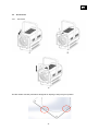
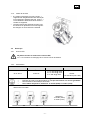
3.1.5 Safety cable
• When hung or flown, the fixture must be
secured by an additional hanging accessory
(such as a safety bond or cable) of suitable
length.
• The combined weight of both the fixture and
the accessories must be considered when
choosing the load-bearing capability of safety
cable or bond.
• Safety cables or bonds must be securely
attached to the back of the fixture and be as
short as possible, or rolled up as necessary,
to minimise travel distance should the fixture
be dislodged.
3.2 Electrical
3.2.1 LED source
Never touch or scratch LED surface.
See 5.1.5 LED cleaning procedure if cleaning is necessary.
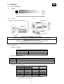
3.2.2 Power
Power supply
Voltage
Frequency
Input power
Connectors
90 & 264 V
47-63 Hz
1,4 A / 300 W @ 230V
2,5 A / 300 W @ 120V
3 A / 300 W @ 100V
Neutrik powerCON TRUE1
Entrée :
ref. NAC3PX (max. 20A)
• Class 1 product. This luminaire must be earthed.
• Must be connected directly to AC power. Do not connect to dimmer power
• Automatic power detection
• On the same breaker, maximum of: 10 units (230V) / 5 units (110V)
Daisy chain:
Maximum:
10 units (230V)
5 units (110V)

EN
- 7 -
Power cable
Power cable
Connector
Mains
plug
Cable type
Cable
length
Wiring
1
Standard
version
Neutrik
PowerCon
True1
CEE7/7
FJUC000112
3 meters
Live: Brown
Neutral: Blue
Earth:Yellow/Green
2
North American
version
-
FJUC000113
1.5 meter
Live: Black
Neutral: White
Earth : Green
3.2.3 DATA
DATA
Protocol
Input connector
Output connector
USITT DMX 512-A
XLR 5-pin
XLR 5-pin
Power up
DATA connectors
PIN #
DMX
Description
1
OV
Foil & Braided Shield
2
DMX (-)
1st conductor of 1st twisted pair
3
DMX (+)
2nd conductor of 1st twisted pair
4
Not used
1st conductor of 2nd twisted pair
5
Not used
2nd conductor of 2nd twisted pair

EN
- 8 -
Wireless DMX option
•Protocol: Wireless Solution W-DMXTM
•Refer to the OEM User’s manual for general
recommendations and use of the transmitter :
http://www.wirelessdmx.com
•The antenna must be clearly visible from the transmitter
•Refer to RJ-LED Software manual for activation procedure
(page EN-18)
•Do not connect a DMX IN data cable in case of
wireless DMX use
DMX mode:
The first unit receives the DMX signal via the wireless network, then all the other units are
connected o the first one via DMX data cable
Integrated terminal plug:
If no XLR connector is detected on DMX OUT connector, a 120Ω terminal plug is automatically
activated. Additional terminal plug on the last unit is not necessary.
Maximum:
32 units

EN
- 9 -
3.3 Accessories
3.3.1 Gel frame
!
"
#
The filter holder includes perforations designed for stapling to keep the gel in position.

EN
- 10 -
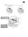
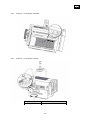
3.3.2 Barndoors
• Movable accessories (barndoors, scroller, etc.) must also be secured with a suitable safety
cable or bond at the front of the fixture.
!
"
#
Front accessories safety cable
attachment point
Filter frame slot
Barndoors slot

EN
-11 -
4 Operation
4.1 Light intensity
4.1.1 Range
4.1.2 Control
HTP mode (Highest Takes Precedence):
Light output is the highest value of DMX512 command or local control
4.1.3 Parameters
•Resolution:
Mode Resolution
8 bits 255 steps – 1 DMX channel
16 bits 65 535 steps – 2 DMX channels
16 bits + Strobe 65 535 steps – 3 DMX channels
•Smoothing
Mode Smoothing
Slow Slow transition between 2 levels – equivalent to 1000W filament
Fast Fast transition between 2 levels – equivalent to 600W filament
Without Deactivated – Very fast transitions
Locally
DMX512-A
DMX Console
Remotely with DMX512-A protocol
0 % 100 %
Focus mode : when standby screen displayed,
Push Exit Light output = 100% for 1 minute
2x times Exit Light output = 0%
•Master mode (MASTER CONTROL):
DMX Local Light output
8/16bits Master
0 100% 100% 0% 0 100%
0 100% 50% 0% 0 50%
0% 100% 0 100% 0 100%
0% 50% 0 100% 0 50%
50% 100% 0 100% 50 100%
30% 80% 0 100% 30 80%
Mode required when simultaneous remote and local control are necessary
(example : followspot)

EN
-12 -
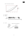
0
50
100
150
200
250
0 50 100 150 200 250
Linear
square
•Curve1: Linear / square
4.2 Strobe
4.2.1 Range
4.2.2 Control
DMX512-A
DMX Console
Remotely with DMX512-A protocol
1 Hz 55 Hz
0 = OFF
1
255

EN
-13 -
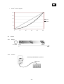
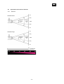
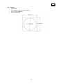
4.3 Beam size adjustment
4.3.1 Range
Field angle
27°
3%
50%
50%
3%
100%
3%
50%
50%
3%
100%
Beam angle
12°
Field angle
93°
Beam angle
64°

EN
-14 -
4.3.2 Control – Manually operated
4.3.3 Control – Pole operated
Colour
Function
Yellow
Focus

EN
-15 -
4.4 Orientation
4.4.1 Range
Function
Range
Manual
Pole operated
PAN
0 & 360°
0 & 360°
TILT
0 & 360°
0 & 45°
4.4.2 Control – Manually operated
4.4.3 Control – Manually operated
Colour
Function
White
TILT
Blue
PAN

EN
-16 -
4.5 Colour
•One fixed colour
•Any standard colour / effect filter gel
•See 3.3.1 for installation
•Size:

EN
-17 -
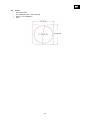
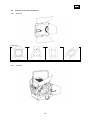
4.6 Beam shaping with barndoors option
4.6.1 Range
4.6.2 Control
Examples:
Open
Triangle
Square
Line

EN
EN - 18 -
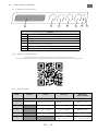
4.7 Control
4.7.1 Display and Controls
exit ˜ + select
ERROR
DATA
1 42 5 6 73
4.7.2 Menus and parameters
Function
1Display
2Exit the current menu option and/or go back
3Scrolls through menus and/or Decrease blinking data value
4Scrolls through menus and/or Increase blinking data value
5Enter the current menu option and/or valid
6Hard CPU reset
7DMX and system LED feedback
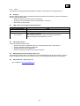
Please scan this QR-Code for the software menu or go to :
www.robertjuliat.com/productSearch.html to nd the latest version.
Mode Theatre Studio Followspot Direct DMX (variable
white)
DMX ch.
1Dimmer (8 bit) Dimmer Coarse (8 bit) Dimmer Coarse (8 bit) WW Coarse (8 bit)
2Dimmer Fine (16 bit) Dimmer Fine (16 bit) WW Fine (16 bit)
3CCT
0 255 : WW CW
CCT
0 255 : WW CW CW Coarse (8 bit)
4Strobe
0 : OFF ; 1 255 : SLOW FAST
Strobe
0 : OFF ; 1 255 : SLOW FAST CW Fine (16 bit)
5Master
0 255 : 0 100% (FULL)
Strobe
0 : OFF ; 1 255 : SLOW FAST
4.7.3 DMX chart
La page est en cours de chargement...
La page est en cours de chargement...
La page est en cours de chargement...
La page est en cours de chargement...
La page est en cours de chargement...
La page est en cours de chargement...
La page est en cours de chargement...
La page est en cours de chargement...
La page est en cours de chargement...
La page est en cours de chargement...
La page est en cours de chargement...
La page est en cours de chargement...
La page est en cours de chargement...
La page est en cours de chargement...
La page est en cours de chargement...
La page est en cours de chargement...
La page est en cours de chargement...
La page est en cours de chargement...
La page est en cours de chargement...
La page est en cours de chargement...
La page est en cours de chargement...
La page est en cours de chargement...
La page est en cours de chargement...
La page est en cours de chargement...
La page est en cours de chargement...
-
 1
1
-
 2
2
-
 3
3
-
 4
4
-
 5
5
-
 6
6
-
 7
7
-
 8
8
-
 9
9
-
 10
10
-
 11
11
-
 12
12
-
 13
13
-
 14
14
-
 15
15
-
 16
16
-
 17
17
-
 18
18
-
 19
19
-
 20
20
-
 21
21
-
 22
22
-
 23
23
-
 24
24
-
 25
25
-
 26
26
-
 27
27
-
 28
28
-
 29
29
-
 30
30
-
 31
31
-
 32
32
-
 33
33
-
 34
34
-
 35
35
-
 36
36
-
 37
37
-
 38
38
-
 39
39
-
 40
40
-
 41
41
-
 42
42
-
 43
43
-
 44
44
-
 45
45


Robert Juliat ZEP2 360LF2 Manuel utilisateur
- Catégorie
- Stroboscopes
- Taper
- Manuel utilisateur
- Ce manuel convient également à
dans d''autres langues
Documents connexes
Autres documents
-
Merlin HMI 2500W FOLLOWSPOT Manuel utilisateur
-
Briteq BT-THEATRE 100EC Le manuel du propriétaire
-
-
Chauvet Professional ONAIRPANEL1IP Mode d'emploi
-
Vari-Lite VLZ WASH Manuel utilisateur
-
-