Merlin HMI 2500W FOLLOWSPOT Manuel utilisateur
- Taper
- Manuel utilisateur

MERLIN - 1515 / C - Version V1 ( v1-12 → )
HMI 2500W FOLLOWSPOT /
PROJECTEUR DE POURSUITE 2500W HMI
FOLLOWSPOT /
VALIDATION: 13/06/2016
DN41076900-B
Manual / Manuel
Standard North American
Standard Nord-Américain
REF 1515 1515C
Robert Juliat S.A.S. 32, rue de Beaumont, F 60530 Fresnoy-en-Thelle - phone : +33 (0)3 44 26 51 89 - fax : +33 (0)3 44 26 90 79 - [email protected]
www.robertjuliat.com

Robert Juliat reserve the right to change or alter any of the items detailed on this page,
to increase or improve manufacturing techniques without prior notice.
Table of Contents
1 User’s instructions ............................................................................................................................................................... 1
2 Presentation ......................................................................................................................................................................... 2
2.1 Functions .....................................................................................................................................................................2
2.2 Identication label .....................................................................................................................................................3
2.3 Accessories included ..................................................................................................................................................3
2.4 Optional accessories ..................................................................................................................................................4
3 Set-up ................................................................................................................................................................................. 5
3.1 Mechanics ...................................................................................................................................................................5
3.1.1 Operating positions
....................................................................................................................................................................................................5
3.1.2 Minimum distance between a ammable material and the lighting unit
..............................................................................5
3.1.3 Instructions for use
......................................................................................................................................................................................................5
3.1.4 Handling
............................................................................................................................................................................................................................ 5
3.1.5 Lifting
..................................................................................................................................................................................................................................5
3.1.6 Stand set-up
....................................................................................................................................................................................................................6
3.1.7 Safety cable
.....................................................................................................................................................................................................................6
3.1.8 Adjustable counterweight inside the followspot
.................................................................................................................................... 6
3.2 Lamp ............................................................................................................................................................................7
3.2.1 Compatible lamp
.........................................................................................................................................................................................................7
3.2.2 Lamp installation
.........................................................................................................................................................................................................7
3.3 Electrical data .............................................................................................................................................................8
3.3.1 Power Supply Unit (PSU)
......................................................................................................................................................................................... 8
3.3.2 Data
..................................................................................................................................................................................................................................... 9
4 Operations .......................................................................................................................................................................... 11
4.1 Mechanics .................................................................................................................................................................11
4.1.1 Dimmer
........................................................................................................................................................................................................................... 11
4.1.1.1 Range
................................................................................................................................................................................................................. 11
4.1.1.2 Control
.............................................................................................................................................................................................................. 11
4.1.2 Zoom & Focus
............................................................................................................................................................................................................. 11
4.1.2.1 Range
................................................................................................................................................................................................................. 11
4.1.2.2 Control
.............................................................................................................................................................................................................. 12
4.1.3 Pan / Tilt
......................................................................................................................................................................................................................... 12
4.1.3.1 Range
................................................................................................................................................................................................................. 12
4.1.3.2 Control
.............................................................................................................................................................................................................. 12
4.1.4 Iris
....................................................................................................................................................................................................................................... 13
4.1.4.1 Range
................................................................................................................................................................................................................. 13
4.1.4. 2 Control
.............................................................................................................................................................................................................. 13
4.1.5 Chopper
......................................................................................................................................................................................................................... 13
4.1.5.1 Range
................................................................................................................................................................................................................. 13
4.1.5.2 Control
............................................................................................................................................................................................................... 13
4.1.6 Gobo
................................................................................................................................................................................................................................. 14
4.1.6.1 Gobo size
.......................................................................................................................................................................................................... 14
4.1.6.2 Control & Installation
............................................................................................................................................................................... 14
4.1.7 Colour
.............................................................................................................................................................................................................................. 14
4.1.7.1 Range
................................................................................................................................................................................................................. 14
4.2 Control .......................................................................................................................................................................15
4.2.1 Display and Controls
............................................................................................................................................................................................. 15
4.2.2 Menus and parameters .......................................................................................................................................................
15
4.2.3 Menus and parameters for DMX dimmer option ..........................................................................................................
24
4.2.4 DMX Chart ..............................................................................................................................................................................
25
5 Service ...............................................................................................................................................................................26
5.1 Preventative maintenance ......................................................................................................................................26
5.1.1 Frequency
..................................................................................................................................................................................................................... 26
5.1.2 General cleaning
....................................................................................................................................................................................................... 26
5.1.3 General visual check
.............................................................................................................................................................................................. 26
5.1.4 Optics
............................................................................................................................................................................................................................... 26
5.1.5 Removing the Power Supply Unit (PSU)
...................................................................................................................................................... 26
5.2 Analysis .....................................................................................................................................................................27
5.3 Thermal protection ..................................................................................................................................................27
5.4 Exploded view / Spare parts list ..............................................................................................................................27
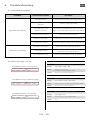
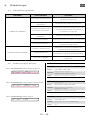
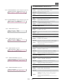
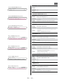
6 Troubleshooting ................................................................................................................................................................28
6.1 General information ................................................................................................................................................28
6.2 Error message screens : ............................................................................................................................................28
7 RDM ..................................................................................................................................................................................... 36
7.1 RDM - What is it? .......................................................................................................................................................36
7.2 RDM requirements ...................................................................................................................................................36
7.3 RDM function list ......................................................................................................................................................36

EN
EN - 1 -
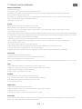
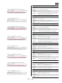
1 User’s instructions
GENERAL INSTRUCTIONS
1. Not for residential use.
2. These fixtures must only be serviced by a qualified technician.
3. In addition to the instructions indicated on this page, relevant health and safety requirements of the appropriate EU
Directives must be adhered to at all times.
4. This fixture is in compliance with section 17 – Lighting appliance for theatre stages, television, cinema and photograph
studios. Standards NF EN 60598-1 and NF EN 60598-2-17.
5. This fixture is rated as IP20.
FIXTURE
6. Warning: disconnect from mains supply before servicing.
7. Ensure fixture is correctly mounted on an appropriate support.
8. Protection screens, lenses and filters must be replaced in the event of any damage, such as cracks or deep scratches,
as these might reduce performance.
9. When hung or flown the fixture must be secured by an additional hanging accessory (such as a safety cable or bond) of suitable length.
10. Safety bonds or cables must be securely attached to the back of the fixture and be as short as possible, or rolled up as necessary,
to minimise travel distance should the fixture be dislodged.
11. Movable accessories must also be secured with a suitable safety cable or bond at the front of the fixture.
12. The combined weight of both the fixture and the accessories must be considered when choosing the load-bearing
capability of safety cable or bond.
13. Do not open lighting fixture when the lamp is ignited.
14. Warning: Both lamp and lamp housing become hot during use. Allow fixture to cool before servicing
15. Do not tamper with design of fixture nor any of its safety features.
16. Tighten electrical mains cable connections regularly and replace with one of identical specification if damaged.
VENTILATION
17. Keep well away from flammable material.
18. Not for outdoor use. Do not cover. Do not permit fixture to get wet.
19. To avoid overheating, do not obstruct air vents.
20. Ensure all cooling fans are in correct working order. If fans are not working, turn fixture off immediately and service as necessary.
LAMP
21. Check that the lamp voltage corresponds to the mains voltage used.
22. Only use a lamp of type and voltage indicated on lamp housing or packaging.
23. Replaced lamp if damaged or deformed by heat.
24. Ensure lamp is correctly fitted before use.
CLEANING
25. Do not touch the lamp and inner parts with bare fingers.
26. Clean all optical parts (lenses, lamps, etc.) with alcohol-based cleaner.
27. Regularly remove dust from mirror with a soft, clean cloth.
28. Clean all filters regularly.
POWER SUPPLY
29. Disconnect from the mains before servicing.
30. Mains connection only. Do not connect to "electronic output" such as dimmer.
31. Not for outdoor use. Do not cover.
32. Ensure power supply circuit breakers always remain accessible.
PLEASE NOTE
These products have been built to conform to European standards relating to professional lighting equipment. Any modification
made to our products will void the manufacturers' warranty.

EN
USB 5V (1 A Max.)
ECO MODE
<1s
LAMP
ON/OFF :
>1s
A B C D E F G H
I
GOBO
FOCUS
EN - 2 -
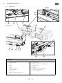
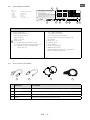
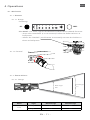
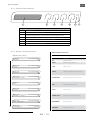
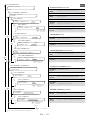
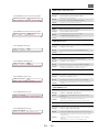
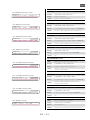
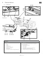
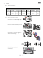
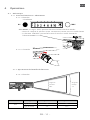
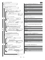
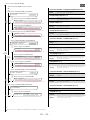
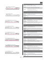
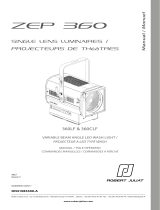
2 Presentation
2.1 Functions
Functions
1. Dimmer/Shutter
2. Iris
3. Focus
4. Zoom
5. Frost
6. Horizontal chopper
7. Vertical chopper
8. Gobo holder
9. Boomerang colour changer unit
A. Display screen
B. ON/OFF Lamp & Eco Mode button
C. Main switch
D. DMX In
E. DMX Out
F. Main socket PowerCON TRUE-1
G. Auxiliary socket (max 3A)
H. Wireless DMX slot
1
6
4
2
7
5
D
E GF
H
B
C
A
38
9
Note: Wireless DMX
optional module

EN
N° SERIE
SERIAL N°
ATTENTION PROJECTEUR A DECHARGE - PRECAUTIONS D'UTILISATION.
WARNING! DISCHARGE SPOTLIGHT - OPERATING INSTRUCTIONS.
• Avant de mettre l'appareil en service, veuillez lire les consignes d'utilisation.
• Amorçage haute tension: mise hors tension obligatoire avant toute intervention.
• Emission de rayons U.V.: Protéger votre vue.
• Lampe et support chauds: attendre que l'appareil soit froid avant toute intervention.
• Intervention par technicien qualié.
• Read user's instructions before using this lighting unit.
• High voltage ignition: disconnect from the mains before any servicing.
• U.V. rays : Protect your eyes.
• Bulb and holder hot: wait until the unit is cold, before servicing.
• Service only by qualied technician.
1515 MERLIN
Made in the EU - France -
.com
BASE / CULOT : S Fa 21
150
OSRAM : HMI 2500W/S
Vers.
20
80kg
IP
t°a
1515
40°C
t°c
110°C
SERIE /
SERIAL
6m
GOBO "A" SIZE
MOD.
DE31050102
PF*PaInput In
208-60Hz 3000VA 14A 0,97 2 Phase
PF*PaInput In
230-50Hz 3000VA 13A 0,96
PF*PaInput In
245-50Hz 3000VA 12A 0,95
Ph+Neutral
Ph+Neutral
EN - 3 -
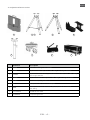
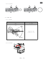
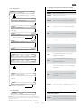
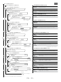
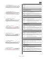
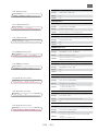
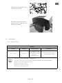
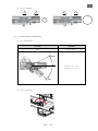
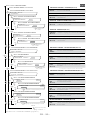
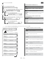
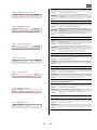
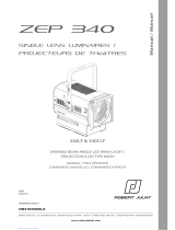
2.2 Identication label
Description
Units :
- Dimensions = metre (m) millimetre (mm).
- Weight = kilogram (kg).
- Intensity = Ampere (A).
- Voltage = Volt (V).
- Frequency = Hertz (Hz).
- Temperature = degree Celsius (°C).
1 User's instructions.
2 Power supply reference &
technical characteristics :
- MOD. = Model.
- VERS. = Version.
- Net weight.
- IP = International protection rating.
- t°a = Maximum ambient temperature (°C).
- t°c = Maximum external temperature
of the unit (°C).
- Pa = Power absorbed.
- In = Nominal intensity.
- PF = Power Factor correction
3 Logo, manufacturer's name and origin of
the product.
4 Gobo size = "A".
5 Lamp reference.
6 Serial number.
7 European conformity.
8 WEEE directive label.
9 Minimum distance between a flammable
material and the followspot.
1
6
2
73 45 89
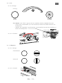
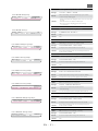
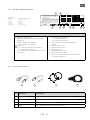
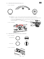
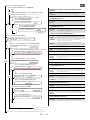
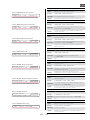
2.3 Accessories included
Reference Description
1 FJUC000112 Power cable with CEE 7/7 type in connectors (standard version)
2 FJUC000113 UL/CSA power cable without connector (North-American version)
3 PF1011 Ø210 mm metal filter holder
4 SGUM Universal "A" size gobo holder (metal or glass)
1 2 3 4

EN
EN - 4 -
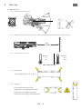
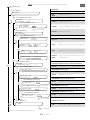
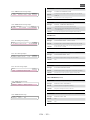
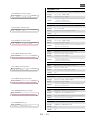
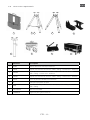
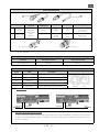
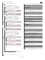
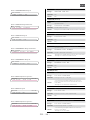
2.4 Optional accessories
Reference Description
1 MOMM Motorised dimming shutter module
2 GT4000 Tripod stand with safety chain - SWL: 130 kg max. height 1030 mm
3 GT4000R
Tripod stand with ball bearing head rotation with safety chain - SWL: 130 kg
max. height 1030 mm
4 GT4000S Tripod stand without safety chain - SWL: 130 kg max. height 1030 mm
5 TELRAD Telrad followspot sight with riser
6 JPP Monopod stand for overhead followspot
7 T4000
Followspot mount for 50 mm diam. pipe (suspension or overhead) -
SWL: 100 kg
8 Kit W-DMX/M W-DMX Wireless DMX
9 FC30000020 Transport Flight Case
1
6
4
9
2
7
5
3
8

EN
EN - 5 -
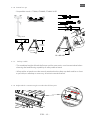
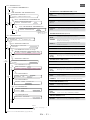
3 Set-up
3.1 Mechanics
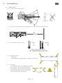
3.1.1 Operating positions
3.1.2 Minimum distance between a ammable material and the lighting unit
3.1.3 Instructions for use
Minimum :
40°C
104°F
5°C
41°F
IP20 - Indoor use only
Maximum :
6 m
19.68 ft
3.1.4 Handling
• Net weight: 80 Kg (176.37 lbs).
3.1.5 Lifting
In accordance with existing
regulations, the appropriate means
and process should be used and
respected when lifting the followspot.
Vertical
Horizontal
45° max.
30° max.

EN
H1
H1 = H2 = H3
H2
H3
725 mm /
1030 mm
130Kg / 286 lb
870 mm /
1070 mm
NO !
EN - 6 -
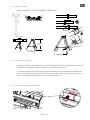
3.1.7 Safety cable
• The combined weight of both the fixture and the accessories must be considered when
choosing the load-bearing capability of safety cable or bond.
• Safety cables or bonds must be securely attached to the safety eye-bolts and be as short
as possible, or rolled up as necessary, to minimise travel distance.
3.1.6 Stand set-up
• Compatible stands : GT4000, GT4000R, GT4000S & JPP.
3.1.8 Adjustable counterweight inside the followspot
1
2

EN
TOP
==
EN - 7 -
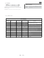
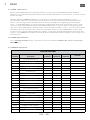
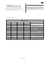
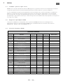
Compatible lamp
Model NAED Code Socket Voltage Power
Lumen
output
Colour
Temperature
Lamp life
OSRAM
HMI 2500W/S XS
54068-3 SFa 21-12 115 V 2500 W 240 000 lm 6 000 K 500 h
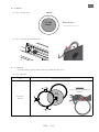
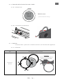
3.2 Lamp
3.2.1 Compatible lamp
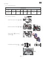
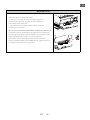
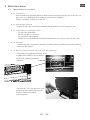
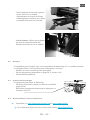
3.2.2 Lamp installation
• Unlock the security screws 1 & 2
• Rotate the reflector holder 3 & 4
• Unlock the jaws 6 by pushing
upwards 7
• Install and center the lamp 8
1
3
6
2
4
7
5
8

EN
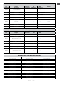
3.3 Electrical data
3.3.1 Power Supply Unit (PSU)
EN - 8 -
Power supply
Voltage Frequency Input power Connectors
195 —> 265 V 50-60 Hz
12 A / 3000 VA @ 230V
13 A / 3000 VA @ 245V
14 A / 3000 VA @ 208V
Max. 16 A
Standby mode: 30 W
Neutrik powerCON TRUE1
ref. NAC3PX (max. 20A)
• Class 1 product. This luminaire must be earthed.
• Must be connected directly to AC power. Do not connect to dimmer power.
• Automatic power detection.
• Thermal breaker switch : 20A.
• Auxiliary power : Max 3A.
• USB power : Max 5V (1A).
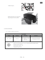
• Relock the jaws
• Relock the lamp cover into place
by pushing the security bolts
9
10
11

EN
EN - 9 -
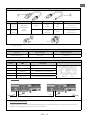
DATA connectors
PIN # DMX Description
1 Shielding Foil & Braided Shield
2 DMX (-) 1
st
conductor of 1
st
twisted pair
3 DMX (+) 2
nd
conductor of 1
st
twisted pair
4 Not used 1
st
conductor of 2
nd
twisted pair
5 Not used 2
nd
conductor of 2
nd
twisted pair
Integrated terminal plug:
If no XLR connector is detected on DMX OUT connector, a 120Ω terminal plug is automatically activated.
Additional terminal plug on the last unit is not necessary.
DMX OUT DMX IN
Daisy chain:
IN INOUT OUT etc.
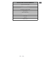
3.3.2 Data
DATA
Protocol Input connector Output connector
USITT DMX 512-A XLR 5-pin XLR 5-pin
2
1
In
Out
Power cable
Power cable Connector Mains plug Cable type Cable length Wiring
1
Standard
version
Neutrik®
powerCON
TRUE1
NAC3FX
CEE7/7
3G1.5
H07RNF
3 m
9.8 ft
Live: Brown
Neutral: Blue
Ground: Yellow/Green
2
North
American
version
-
14AWG
SJ TYPE
(UL/CSA)
1.5 m
4.9 ft
Live: Black
Neutral: White
Ground: Green

EN
EN - 10 -
Wireless DMX option
• Protocol: Wireless Solution W-DMX™
• Refer to the OEM User’s manual for general recommendations and
use of the transmitter:
http://www.wirelessdmx.com
• The antenna must be clearly visible from the transmitter
• See MENU for activation
• Do not connect a DMX IN data cable in case of wireless DMX use
• In case of protocol errors, the wireless DMX is automatically
deactivated. To activate the wireless DMX again, disconnect the
DMX IN data cable, and then switch the unit off and on.
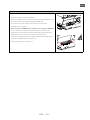
• Installation: Remove the power supply from the followspot head.
Insert the W-DMX module into the slot.
Reconnect the power supply unit.

EN
EN - 11 -
4 Operations
4.1 Mechanics
4.1.1 Dimmer
4.1.1.1 Range
• Dimming
• Eco-Mode : the "ECO" sign on the dimmer enables the Eco-Mode function:
• Starts the countdown (3 or 15 minutes) before the ballast douses at
half power
• Allows the "ON/OFF" push button to manually activate the ballast to
douse at half power
4.1.2 Zoom & Focus
4.1.2.1 Range
Model Angles Minimum angle Maximum angle
1515
Beam angle 3.4° 10.6°
Field angle 3.5° 12.1°
Beam angle
50%
Field angle
3%
0% 100%
4.1.1.2 Control
USB 5V ( 1A Max.)
ECO MODE
<1s
LAMP
ON/OFF :
>1s

EN
ZOOM ZOOMFOCUS FOCUS
Up
Down
EN - 12 -
4.1.3 Pan / Tilt
4.1.3.1 Range
4.1.3.2 Control
4.1.2.2 Control
Function Range
PAN 0 —> 360°
TILT
Tilt up = 0 —> 30°
Tilt down = 0 —> 45°
1 12 2

EN
A B C D E F G H
I
GOBO
FOCUS
EN - 13 -
4.1.4 Iris
4.1.4.1 Range
• Irising
4.1.4. 2 Control
4.1.5 Chopper
4.1.5.1 Range
• Horizontal
• Vertical
4.1.5.2 Control
OPEN CLOSED
• Eco-Mode : the "ECO" sign on the iris enables the Eco-Mode function:
• Starts the countdown (3 or 15 minutes) before the ballast douses at
half power
• Allows the "ON/OFF" push button to manually activate the ballast to
douse at half power
USB 5V ( 1A Max.)
ECO MODE
<1s
LAMP
ON/OFF :
>1s

EN
A B C D E F G H
I
GOBO
FOCUS
EN - 14 -
4.1.6 Gobo
4.1.6.1 Gobo size
4.1.6.2 Control & Installation
Type Standard coloured gel filter
Dimension
210 mm
4.1.7 Colour
• Fixed colour: place dark colours towards the rear.
4.1.7.1 Range
Metal & Glass
(*) Maximum image size
"A" Size
72 mm*
100 mm
Installation :
push firmly until clicked into
position.

EN
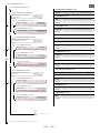
EN - 15 -
exit – + select
ERROR
DATA
4.2 Control
4.2.1 Display and Controls
Function
1 LCD display
2 Exit the current menu / page
3 Scrolls through menus and/or Decrease blinking data value
4 Scrolls through menus and/or Increase blinking data value
5 Enter the current menu option and/or validate
6 NA
7 DMX and system LED feedback
1 42 5 6 73
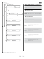
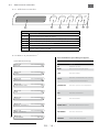
4.2.2 Menus and parameters
1
1
With factory settings
When followspot is turned on:
Initialisation screens (brief display)
Name
MERLIN
SN
Serial number
MAINS
Mains voltage status
LAMP
Lamp status
SAFETY
Safety & thermal switches status
TEMPERATURE
All temperature sensors status
FAN
All working fans status
FUSES
Fuses status
POWER SUPPLY
Internal power supply status
DMX DIMMER
Dimmer status
FIRMWARE
Firmware version
MERLIN
MERLIN
MERLIN
MERLIN
MERLIN
MERLIN
MERLIN
MERLIN
MERLIN
MAINS
LAMP
SAFETY
TEMPERATURE
FAN
FUSES
POWER SUPPLY
DMX DIMMER
FIRMWARE
SN:XXXXXXXX
SN:XXXXXXXX
SN:XXXXXXXX
SN:XXXXXXXX
SN:XXXXXXXX
SN:XXXXXXXX
SN:XXXXXXXX
SN:XXXXXXXX
SN:XXXXXXXX
OK
OK
OK
OK
OK
OK
OK
OK
VX.XX
Initialisation screens (@ start-up)

EN
EN - 16 -
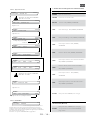
DIMMER:
DIMMER:
DIMMER:
DIMMER:
DIMMER:
DIMMER:
DIMMER:
DIMMER:
DIMMER:
DIMMER:
DIMMER:
FIXTURE: STAND-BY
BALLAST: POWER ON
LAMP: SWITCH-OFF
LAMP: OFF-COOLING XXX
FIXTURE: ERROR
LAMP: IGNITION
LAMP: ON - FULL
LAMP: WARM-UP XXX
LAMP: ON - ECO MODE
LAMP: ON - DMX . DIM:
LAMP: ECO - DMX . DIM:
XXX%
XXX%
0%
0%
0%
XXX%
XXX%
XXX%
XXX%
XXX%
XXX%
0%
XXX%
<-- Stand-by screen (after 30 seconds of non-activity)
System functions (Level 0)
DIMMER
Dimmer value status
FIXTURE
Followspot on stand-by
BALLAST
Mains voltage : OK | ERROR | WARNING
LAMP
Ignition status : OK | ERROR | WARNING
LAMP
Warm-up status : OK | ERROR | WARNING
LAMP
Lamp ON status : OK | ERROR | WARNING
LAMP
Eco mode status : OK | ERROR | WARNING
LAMP*
Lamp ON, DMX dimmer status : OK |
ERROR | WARNING
LAMP*
Eco mode, DMX dimmer status : OK |
ERRROR | WARNING
LAMP
Lamp switched OFF status : OK | ERROR |
WARNING
LAMP
Lamp OFF, cooling status : OK | ERROR |
WARNING
FIXTURE
Followspot status : ERROR (not corrected)
Function error (Level 0)
FIXTURE
Followspot status : ERROR (not corrected)
Refer to section FIXTURE ERROR page EN-27
(*) If DMX option available
Level 0 - FIXTURE Stand-by
Level 0 - FIXTURE ERROR
Press ON/OFF button: >1 second
Press ON/OFF button: >1 second
After 1s
After 3s
After 3s
Warm-up time: 180s
After 180s (delay timer)
Refer to page EN-27 for more details
WARNING: If a message error appears, to continue using the followspot,
the user must press the ON/OFF push button to validate that the message
has been recognised.
PROCEDURE: Go to Fixture Status to check the parameters, page EN-21.

EN
EN - 17 -
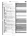
Level 0 - FIXTURE Stand-by
Select
Select
DMX SETUP
DMX SETUP
DMX SETUP
DMX SETUP
DMX SETUP
DMX ADDRESS
DMX DATA
DIMMER COARS DMX @ xxx
WIRELESS DMX ¥
WIRELESS DMX ¥
WIRELESS DMX ¥
WIRELESS DMX ¥
WIRELESS DMX ¥
DIMMER FINE DMX @ xxx
CONTROL MODE DMX @ xxx
-> ADDRESS XXX
-> DMX DATA
-> WIRELESS DMX ¥
-> RDM
-> CHANNEL: XXX
PROTOCOL: XXXXX
VALUE: XX%- (YYY)
-> XXXXXXXXXXXXxXXX
-> POWER: XXX
-> UNLINK: XXX
-> UNLINK: XXX
-> POWER: XXX
VALUE: XX%- (YYY)
VALUE: YYY XXXXXXxXXX
DMX SETUP
Function (Level 1)
DMX
SETUP
DMX setup mode
DMX ADDRESS (Level 2)
ADDRESS
DMX address status
CHANNEL
Select your DMX channel number
DMX DATA
DMX data function
DMX DATA PROTOCOL mode (Level 3)
PROTOCOL
DMX protocol status: DMX | NONE | ERROR
VALUE
DMX coarse value : Level(%) & Level (DEC)
VALUE
DMX fine value : Level(%) & Level (DEC)
CONTROL
MODE
Control mode status with its given value
and its function
DMX WIRELESS function (Level 2)
(*) Warning : RDM must be OFF to use the wireless function
WIRELESS
DMX wireless status : OFF | ON | RDM ON*
DMX WIRELESS data (Level 3)
->
DMX wireless device values
POWER
DMX wireless status
DMX WIRELESS activation mode (Level 4)
POWER
DMX wireless function mode : OFF | ON
DMX WIRELESS data (Level 3)
UNLINK
DMX wireless link/unlink status
DMX WIRELESS UNLINK mode (Level 4)
UNLINK
DMX wireless link/unlink mode : OFF | ON
RDM function (Level 2)
RDM
Remote Device Management mode
Select
Exit
Exit
Exit
Go to next page -->
Next screen: FIXTURE RESET (page EN-18)
Exit
Exit
Exit
Exit
Exit
Level 1 - DMX Setup
Level 2 - DMX Setup address status
Level 2 - DMX Data status
Level 2 - DMX Wireless function*
Level 2 - RDM function
Level 3 - DMX Data protocol mode
Level 3 - DMX Wireless data
Level 3 - DMX Wireless unlink data
Level 4 - DMX Wireless activation mode
Level 4 - DMX Wireless unlink mode
Level 3 - DMX Setup address mode
Press the SELECT
button to validate
Press the SELECT
button to validate
Press the SELECT
button to validate
Select
Select
Select
Select
Select
NOTA: Best practice, settings should be executed with lamp OFF.

EN
EN - 18 -
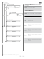
Exit
RDM
RDM
RDM
RDM
RDM
RDM
RDM
Activation : XXX
Activation : XXX
Serial: XXXXXXXX
Name_1: XXXXXXXX
Name_2: XXXXXXXX
Name_3: XXXXXXXX
Name_4: XXXXXXXX
RDM Activation function (Level 3)
(*) Warning : DMX Wireless must be OFF to use the RDM function
Activation
RDM activation status*
RDM Activation mode (Level 4)
Activation
RDM activation mode : OFF | ON | W-DMX ON
RDM Activation data (Level 3)
Serial
Identification number
Name - 1
Displays the first 8 characters of the
followspot name
Name - 2
Displays the next 8 characters of the
followspot name
Name - 3
Displays the next 8 characters of the
followspot name
Name - 4
Displays the last 8 characters of the
followspot name
Level 1 - DMX Setup
Level 2 - RDM function
Select
Select
Level 4 - RDM Activation mode
Level 3 - RDM Activation status*
Level 3 - RDM Activation data
Press the SELECT
button to validate
Press the SELECT
button to validate
Next screen: FIXTURE SETUP (page EN-19)
Nota: Name contains up to 32 characters
Exit Exit
La page est en cours de chargement...
La page est en cours de chargement...
La page est en cours de chargement...
La page est en cours de chargement...
La page est en cours de chargement...
La page est en cours de chargement...
La page est en cours de chargement...
La page est en cours de chargement...
La page est en cours de chargement...
La page est en cours de chargement...
La page est en cours de chargement...
La page est en cours de chargement...
La page est en cours de chargement...
La page est en cours de chargement...
La page est en cours de chargement...
La page est en cours de chargement...
La page est en cours de chargement...
La page est en cours de chargement...
La page est en cours de chargement...
La page est en cours de chargement...
La page est en cours de chargement...
La page est en cours de chargement...
La page est en cours de chargement...
La page est en cours de chargement...
La page est en cours de chargement...
La page est en cours de chargement...
La page est en cours de chargement...
La page est en cours de chargement...
La page est en cours de chargement...
La page est en cours de chargement...
La page est en cours de chargement...
La page est en cours de chargement...
La page est en cours de chargement...
La page est en cours de chargement...
La page est en cours de chargement...
La page est en cours de chargement...
La page est en cours de chargement...
La page est en cours de chargement...
La page est en cours de chargement...
La page est en cours de chargement...
La page est en cours de chargement...
La page est en cours de chargement...
La page est en cours de chargement...
La page est en cours de chargement...
La page est en cours de chargement...
La page est en cours de chargement...
La page est en cours de chargement...
La page est en cours de chargement...
La page est en cours de chargement...
La page est en cours de chargement...
La page est en cours de chargement...
La page est en cours de chargement...
La page est en cours de chargement...
La page est en cours de chargement...
La page est en cours de chargement...
La page est en cours de chargement...
La page est en cours de chargement...
La page est en cours de chargement...
La page est en cours de chargement...
-
 1
1
-
 2
2
-
 3
3
-
 4
4
-
 5
5
-
 6
6
-
 7
7
-
 8
8
-
 9
9
-
 10
10
-
 11
11
-
 12
12
-
 13
13
-
 14
14
-
 15
15
-
 16
16
-
 17
17
-
 18
18
-
 19
19
-
 20
20
-
 21
21
-
 22
22
-
 23
23
-
 24
24
-
 25
25
-
 26
26
-
 27
27
-
 28
28
-
 29
29
-
 30
30
-
 31
31
-
 32
32
-
 33
33
-
 34
34
-
 35
35
-
 36
36
-
 37
37
-
 38
38
-
 39
39
-
 40
40
-
 41
41
-
 42
42
-
 43
43
-
 44
44
-
 45
45
-
 46
46
-
 47
47
-
 48
48
-
 49
49
-
 50
50
-
 51
51
-
 52
52
-
 53
53
-
 54
54
-
 55
55
-
 56
56
-
 57
57
-
 58
58
-
 59
59
-
 60
60
-
 61
61
-
 62
62
-
 63
63
-
 64
64
-
 65
65
-
 66
66
-
 67
67
-
 68
68
-
 69
69
-
 70
70
-
 71
71
-
 72
72
-
 73
73
-
 74
74
-
 75
75
-
 76
76
-
 77
77
-
 78
78
-
 79
79


Merlin HMI 2500W FOLLOWSPOT Manuel utilisateur
- Taper
- Manuel utilisateur
Autres documents
-
 Robert Juliat ZEP2 360LF2 Manuel utilisateur
-
 Robert Juliat ZEP 340CLF Manuel utilisateur
-
Martin MAC III Profile Manuel utilisateur
-
Martin MAC III PERFORMANCE Manuel utilisateur
-
Martin MAC III Wash Manuel utilisateur
-
CHAUVET DJ LEDFOLLOWSPOT120ST Guide de démarrage rapide
-
Martin MAC Ultra Performance Mode d'emploi
-
Chauvet MAVERICK Guide de référence
-
-

