Norcold N62/N82 Series Le manuel du propriétaire
- Taper
- Le manuel du propriétaire

WARNING: Improper installation, adjustment, alteration, service or maintenance
can cause personal injury or property damage. Refer to this manual.
For assistance or additional information, contact a qualied installer,
service agency, or the gas supplier.
FOR YOUR SAFETY
Do not store or use gasoline or other ammable vapors and liquid in the
vicinity of this or any other appliance.
FOR YOUR SAFETY
If you smell gas:
1. Open windows
2. Don’t touch electrical switches.
3. Extinguish any open ame.
4. Immediately call your gas supplier.
For N62X and N62XXX models: 6 cu.ft., 2-way, R.V. refrigerators.
For N64X and N64XXX models: 6 cu.ft., 2-way or 3-way, R.V. refrigerators.
For N64XIM and N64XIMXX models: 6 cu.ft., 2-way, R.V. refrigerators with ice maker.
For N82X and N82XXX models: 8 cu.ft., 2-way, R.V. refrigerators.
For N84X and N84XXX models: 8 cu.ft., 2-way or 3-way, R.V. refrigerators.
For N84XIM and N84XIMXX models: 8 cu.ft., 2-way, R.V. refrigerators with ice maker.
The model numbers of 3-way refrigerators include “.3”. The model numbers of 2-way
refrigerators do not.
The letter “X”, in the model numbers above, stands for a letter or a numeral which means a
refrigerator option.
NORCOLD, Inc.
P.O. Box 4248
Sidney, OH 45365-4248
Part No. 632223A (11-07)
English
Owner’s Manual
Norcold Customer Service Dept.
Telephone: 800-543-1219
Fax: 937-497-3183
Web Site: www.norcold.com
!

Owner’s Manual 2
Table of Contents
For dened warranty terms, please see the one page warranty
statement included in the product information packet.
Safety Awareness .........................................................................2
Safety Instructions ........................................................................2
About Your Refrigerator ................................................................3
Storage volume .....................................................................
3
Leveling .................................................................................
3
Operation during travel ..........................................................3
Food compartment ................................................................
3
Freezer compartment ............................................................
3
Crisper(s) ...............................................................................
3
Door bins ...............................................................................
3
Door bin slide (N64X, N64XXX, N64XIM, N64XIMXX, N84X,
N84XXX, N84XIM, and N84XIMXX models ) .................
3
Adjustable shelves ................................................................
3
Door handles .........................................................................
4
Interior light
............................................................................4
Door alarm (N64X, N64XXX, N64XIM, N64XIMXX, N84X,
N84XXX, N84XIM, and N84XIMXX models ) .................4
Moisture reduction heater
......................................................4
Temperature control system
Backup operating system ......................................................
4
Temperature switch monitor ..................................................
4
Operating the Refrigerator Controls (N62X, N62XXX, N82X,
and N82XXX models) ............................................................
5
Control panel .........................................................................
5
Automatic mode operation ....................................................
5
Removing air from the propane gas supply lines ..................
5
Set the controls to automatic mode operation .......................
6
Set the controls to manual mode operation
...........................6
Operating the Refrigerator Controls (N64X, N64XXX, N64XIM,
N64XIMXX, N84X, N84XXX, N84XIM, and N84XIMXX
models)
..................................................................................7
Control panel .........................................................................
7
Automatic mode operation ....................................................
7
Removing air from the propane gas supply lines ..................
7
Set the controls to automatic mode operation .......................
8
Set the controls to manual mode operation
...........................8
Effects of HIgh Altitude on Propane Gas Operation .....................9
Ice Maker (N64X-IM, N64XIMXX, N84X-IM, and N84XIMXX
models)
..................................................................................9
Ice maker operation
...............................................................9
Refrigerator Care Checklist ........................................................10
Defrosting ...................................................................................10
Cleaning .....................................................................................
11
Interior .................................................................................
11
Drip tray ...............................................................................
11
Metal doors
.......................................................................... 11
Door Sealing ............................................................................... 11
Refrigerator Maintenance Checklist .......................................... 11
Refrigerator Storage ...................................................................12
Ice Maker Storage (N64X-IM, N64XIMXX, N84X-IM, and
N84XIMXX models) .............................................................
12
Refrigerator Maintenance ...........................................................12
Gas ame appearance ........................................................
12
Remove and clean the burner orice ..................................
13
Remove the Refrigerator ............................................................13
Reinstall the Refrigerator ............................................................14
Replacement Parts ....................................................................14
Wiring Diagram and Pictorial ......................................................14
Ice Maker Wiring Pictorial and Diagram (N64X-IM, N64XIMXX,
N84X-IM, and N84XIMXX models)
......................................14
Ice Maker Wiring Pictorial and Diagram (model N843-IM) .........15
Fault Codes (N62X, N62XXX, N82X, and N82XXX models)......15
Fault Codes (N64X, N64XXX, N64XIM, N64XIMXX, N84XIM
N84XXX, N84XIM, and N84XIMXX models) .......................
16
Safety Instructions
Safety Awareness
Read this manual carefully and understand the contents before
you use the refrigerator.
Be aware of possible safety hazards when you see the safety
alert symbol on the refrigerator and in this manual. A signal word
follows the safety alert symbol and identies the danger of the
hazard. Carefully read the descriptions of these signal words to
fully know their meanings. They are for your safety.
WARNING: This signal word means a hazard, which if
ignored, can cause dangerous personal injury, death, or
much property damage.
CAUTION: This signal word means a hazard, which if
ignored, can cause small personal injury or much property
damage.
WARNING:
- The storage of ammable materials behind or around
the refrigerator creates a re hazard. Do not use the
area behind the refrigerator to store anything, especially
ammable materials (gasoline, cleaning supplies, etc.)
- Do not remove the round ground prong from any of the
AC power cords. Do not use a two prong adapter or an
extension cord with any of the AC power cords.
- A circuit overload can result in an electrical re if the
wires and/or fuses are not the correct size. Use only
the wire and fuse sizes as writtten in the “Installation
Manual”.
- Incorrect installation, adjustment, change to, or
maintenance of this refrigerator can cause personal
injury, property damage, or both. Have service and
maintenance work done by your dealer or by an Norcold
authorized service center.
- Disconnect both the AC and DC power sources before
doing any maintenance work on the refrigerator. All
service work on this refrigerator must be done by a
qualied service technician.
- Do not bypass or change the refrigerator’s electrical
components or features.
- When you discard an appliance, remove all doors to
prevent accidental entrapment and suffocation.
!
!
!

Owner’s Manual 3
For the best cooling performance:
- Let air move freely inside the entire food compartment.
- Do not cover the shelves with plastic, paper, etc.
To decrease the amount of ice that collects on the cooling ns:
- Cover all liquids and moist foods.
- Let all hot foods cool before putting them in the refrigerator.
- Do not open the door any longer than necessary.
Freezer compartment:
The freezer compartment is made to keep pre-frozen food frozen
and not to quick freeze food. Keep pre-frozen foods in the
freezer compartment.
NOTE: Do not put other items on the ice tray while the water
is freezing. The water freezes more rapidly if the
thermostat is at the COLDEST position.
Crisper(s):
The crisper(s) are located at the bottom of the fresh food
compartment and supply a storage area to preserve fruit and
vegetable freshness. Make sure that you always push the
crispers fully in.
NOTE: Do not wash the crispers in a dishwasher. The crispers
are not dishwasher safe.
Door bins:
You may put the door bins [52] of the freezer and fresh food
compartment in a location that best meets your needs (See
Art00989). To remove the bins, lift them over the locator and pull
them forward. To install the bins, push them onto the locator.
NOTE: Do not wash the door bins and bin slides in a
dishwasher. The door bins and bin slides are not
dishwasher safe.
Door bin slide:
(N64X, N64XXX, N64XIM, N64XIMXX, N84X,
N84XXX, N84XIM, and N84XIMXX models)
Each door bin includes an adjustable door bin slide [53] to
prevent the bin contents from moving or overturning during transit
(See Art00989).
Push each door bin slide against the bin contents. To remove
each door bin slide, rotate it out of the bin. Rotate the each bin
slide to into the bin to install.
Adjustable shelves:
The shelves in the freezer and the fresh food compartment are
made so you can remove them or move them.
- Do not spray liquids near electrical outlets, connections,
or the refrigerator components. Many liquids are
electrically conductive and can cause a shock hazard,
electrical shorts, and in some cases re.
- The refrigerator cooling system is under pressure. Do
not try to repair or to recharge a defective cooling
system. The cooling system contains sodium chromate.
The breathing of certain chromium compounds can
cause cancer. The cooling system contents can cause
severe skin and eye burns, and can ignite and burn with
an intense ame. Do not bend, drop, weld, move, drill,
puncture, or hit the cooling system.
- At regular intervals, make sure that the refrigerator
ue the burner, the vent areas, and the ventilation air
pathway between the vents are completely free from
any ammable material or blockage. After a period of
storage, it is especially important to check these areas
for any ammable material or blockage caused by
animals.
CAUTION:
- The rear of the refrigerator has sharp edges and
corners. To prevent cuts or abrasions when working on
the refrigerator, be careful and wear cut resistant gloves.
About Your Refrigerator
Storage Volume:
This refrigerator is made for storage of foods and frozen food and
for making ice.
N600 models N800 models
Total capacity 6.3 cubic feet 7.5 cubic feet
Leveling:
CAUTION: The refrigerator is made to operate within
3° off level side-to-side and 6° off level front-to-back (as
looking at the front of the refrigerator). Operating it at more
than these limits can cause damage to the cooling system
and create a risk of personal injury or property damage.
Make sure the vehicle is level before you operate the
refrigerator.
Operation during travel:
While the refrigerator should be level when the vehicle is
stopped, performance during travel is not usually effected.
Food compartment:
Start up the refrigerator and let it cool for eight hours before
loading with food. If the refrigerator does not start to cool
down after about two hours, contact your dealer or a Norcold
authorized service center.
!
!

Owner’s Manual 4
To remove or move the shelf of the freezer:
- Pull the shelf forward out of the slot.
- Push it fully into the slot that you wish.
To remove or move the shelves of the fresh food compartment:
- Remove the screws [41] from the retainer [54] on the side of
the refrigerator (See Art00992).
- Remove the retainer.
- Pull each shelf forward out of the slot.
- Push each fully into the slot that you wish.
- Install the retainer with the screws.
Door handles:
During travel, the door latch prevents the door from opening.
When closing each door, push the door toward the refrigerator
until you hear a “click” sound.
To open each door, pull the handle away from the refrigerator
(See Art00990).
During storage, the storage latch prevents the door from
completely closing. Use it to prevent odors when the refrigerator
is stored for an extended period of time.
To operate the storage latch (see Art00991), open each door
about 1/2 inch, hold the door handle in the open position, and
push the storage latch [55] into the cutout [56] of the strike plate.
Do not use the storage latch as a travel latch because the doors
will not be fully closed.
Interior light:
The interior light is at the top of the fresh food compartment. It
comes on when the refrigerator is ON and the door is open. To
replace the bulb:
1. Remove the DC power supply wires from the power board at
the rear of the refrigerator.
2. To remove the cover [57] , push it toward the rear of the
refrigerator (See Art00988).
3. Remove the light bulb [58] from the holder [59].
NOTE: Use only a GE#214-2 bulb as the replacement bulb. This
bulb is available at most retail automotive parts centers.
4. Install the replacement bulb.
5. Install the cover.
6. Connect the DC power supply wires to the power board at the
rear of the refrigerator.
Door alarm:
(N64X, N64XXX, N64XIM, N64XIMXX, N84X,
N84XXX, N84XIM, and N84XIMXX models)
The refrigerator has an alarm to alert you if the fresh food
compartment door is not closed. The refrigerator continues to
operate, but if the fresh food compartment door is open and the
interior light remains on for two minutes:
- An audible alarm starts.
- “dr” appears in the center display.
- The interior light automatically turns off.
Close the door to silence the alarm.
Moisture reduction heater:
The refrigerator has a heater that prevents moisture from forming
on the center divider between the doors of the freezer and the
fresh food compartment. The heater operates only when the
refrigerator is ON and the DC power is sufcient.
Temperature control system:
Although the refrigerator is not frost -free, it is made to limit frost
on the cooling ns. At regular intervals, the temperature control
system automatically melts most of the frost from the cooling
ns. The water from the cooling ns drains into a collection cup
that is attached to the back of the refrigerator. The heat of the
cooling system evaporates the water from the collection cup.
Backup operating system:
This refrigerator has a backup operating system. The backup
operating system allows the regerator to continue to cool if the
temperature sensor of the refrigerator should fail.
If this failure occurs:
- The refrigerator automatically changes to the backup
operating system.
- When you push the TEMP SET button, the temperature
setting ashes in the center display for ten seconds.
- After the temperature setting ashes, the mode of
operation appears in the center dispaly.
- The backup operating system can overfreeze or thaw the
contents of the freezer and the fresh food compartment.
- Make sure the temperatures of the freezer and the fresh
food compartment are satisfactory.
Temperature switch monitor:
The refrigerator is equipped with a temperature switch [142] for
overheating protection (See Art01869) . A Norcold authorized
service technician can determine if this switch has been
triggered.

Owner’s Manual 5
AC
AUTO
1-COLD
LP GAS TEMP
SET
ON
OFF
MODE
Art01019
30
32
31
34
33
35
36
COLDEST-9
- Push the TEMP SET button and the temperature setting “1-9”
appears in the center display [33].
- Push and hold the TEMP SET button and the temperature
setting changes.
- When the desired temperature setting shows, release
the TEMP SET button.
- The temperature setting shows for ten seconds and then
the current operation mode of the refrigerator shows.
- The number “9” is the coldest temperature setting.
The MODE button [31] controls the operation mode of the
refrigerator.
- Push and hold the MODE button and a light bar shows in the
center display beside each of the operating modes of the
refrigerator, one at a time.
- There is one automatic mode of operation and two
manual modes of operation.
- When the light bar shows beside the mode of operation
that you choose, release the MODE button to operate
the refrigerator in that mode.
Automatic mode operation:
When the refrigerator is in AUTO mode, it automatically uses
the most efcient energy source that is available for operation.
During operation, if a more efcient energy source becomes
available, the refrigerator controls change from the current
energy source to the more efcient energy source as follows:
- The rst choice is AC operation if 120 volts AC is available to
the refrigerator.
- The second choice is propane gas operation if 120 volts AC
is not available to the refrigerator.
Removing air from the propane gas supply lines:
For safety reasons, the burner is made to ignite on propane gas
within a specied amount of time. When starting the refrigerator
for the rst time, after storage, or after replacing propane gas
tank, the propane gas supply lines can have air in them. Due
to the air in the gas supply lines, the burner may not ignite on
propane gas within the specied amount of time.
To remove the air from the propane gas supply lines:
- Make sure that all of the gas valves are open.
- Push the ON / OFF button to turn the refrigerator on.
Operating the Refrigerator Controls
(N62X, N62XXX, N82X, and N82XXX
models)
Control panel:
The refrigerator control panel (see Art01019) is between the
freezer compartment and the fresh food compartment. A 12 volt
DC power supply is necessary for the control functions of the
refrigerator to operate. The refrigerator receives DC power from
the 12 volt system of the vehicle; either an auxiliary battery, a
converter, or the vehicle engine battery.
The ON / OFF button [30] starts and shuts down the refrigerator:
- To turn on the refrigerator, push and release the ON / OFF
button.
- To turn off the refrigerator, push the ON / OFF button for one
second and then release.
The TEMP SET button [32] controls the temperature adjustment
of the freezer and the fresh food compartment. The temperature
adjustment that you select does not change if the mode of
operation of the refrigerator changes.
NOTE: If you open the door(s) too often, the temperatures
inside the freezer and fresh food compartment
do not become stable. Allow the refrigerator to
operate for about one hour after each adjustment
change before you examine the contents. The
number “9” is the coldest temperature setting.
- If the temperature is too warm, push and hold the
TEMP SET button to raise the temperature setting
by one number.
- If the temperature is too cold, push and hold the
TEMP SET button to lower the temperature setting
by one number.
- Have the refrigerator serviced by your dealer or a Norcold
authorized Service Center as soon as possible.

Owner’s Manual 6
- Push and hold the MODE button until the light bar beside LP
GAS shows.
- This means that the refrigerator is operating on propane
gas.
- If the air in the propane gas supply lines prevents the
burner from ignition on propane gas, the fault code “F”
will appear in the center display.
- Push and hold the ON / OFF button for one second and
then release to turn the refrigerator off.
- Push the ON / OFF button to turn the refrigerator on.
- The refrigerator will start a 30 second trial for ignition.
- During the 30 second trial for ignition, the
refrigerator controls open the gas safety valve and
the igniter sparks.
- After 30 seconds, the refrigerator controls closes the
gas safety valve and the igniter stops sparking.
- When the light bar beside the LP GAS [6] shows and no fault
code remains, this means that the refrigerator is operating
on propane gas.
- At this time, all of the air is removed from the propane
gas supply lines and you may select AUTO mode of
operation if you wish.
- Depending on how much air may be in the propane gas
supply lines, you may need to repeat the 30 second trial for
ignition two or three times.
- If the burner does not ignite on propane gas after two or
three attempts, stop and consult your local dealer or an
authorized Norcold Service Center.
Set the controls to automatic mode operation:
- Push the ON / OFF button to turn the refrigerator on.
- Push and hold the MODE button until the light bar shows
beside AUTO [34] and then release.
- If 120 volts AC is available to the refrigerator:
- The light bar beside AC [4] also shows in the center
display.
- After ten seconds, the light bar beside AC goes off and
only the light bar beside AUTO remains.
- This means that the refrigerator is operating on AC
electric.
- If 120 volts AC is not available to the refrigerator:
- The light bar beside AC [35] also shows in the center
display.
- After a few seconds, the light bar beside AC goes off and
the light bar beside LP GAS [36] shows.
- After 10 seconds, the light bar beside LP GAS goes off
and only the light bar beside AUTO remains.
- This means that the refrigerator is operating on propane
gas.
If an energy source is available to the refrigerator, but is not
operating correctly:
- A fault code shows in the center display.
- The refrigerator controls try to change to a less efcient
energy source.
- If a less efcient energy source is not available:
- A fault code shows in the center display.
- Refer to the “Fault Codes” section of this manual.
Set the controls to manual mode operation:
- Push the ON / OFF button to turn the refrigerator on.
- Push and hold the MODE button until the light bar shows
beside AC [35] and then release.
- This means that the refrigerator is operating on AC
electric.
- Push and hold the MODE button until the light bar shows
beside LP GAS [36] and then release.
- This means that the refrigerator is operating on propane
gas.
If the energy source is interrupted:
- A fault code shows in the center display.
- Refer to the “Fault Codes” section of this manual.

Owner’s Manual 7
Operating the Refrigerator Controls
(N64X, N64XXX, N64XIM, N64XIMXX, N84X,
N84XXX, N84XIM, and N84XIMXX models)
Control panel:
The refrigerator control panel (See Art01018) is between the
freezer compartment and the fresh food compartment. A 12 volt
DC power supply is necessary for the control functions of the
refrigerator to operate. The refrigerator receives DC power from
the 12 volt system of the vehicle; either an auxiliary battery, a
converter, or the vehicle engine battery.
The ON / OFF button [30] starts and shuts down the refrigerator:
- To turn on the refrigerator, push and release the ON / OFF
button.
- To turn off the refrigerator, push the ON / OFF button for one
second and then release.
The TEMP SET button [32] controls the temperature adjustment
of the freezer and the fresh food compartment. The temperature
adjustment that you select does not change if the operation mode
of the refrigerator changes.
- Push the TEMP SET button and the temperature setting (the
numbers “1-9”) show in the center display [33].
- The number “9” is the coldest temperature setting.
- Push and hold the TEMP SET button and the temperature
setting changes.
- Release the TEMP SET button when the temperature setting
that you wish appears.
- After ten seconds, the temperature setting will go out and
only a green power ON light remains.
The MODE button [31] controls the operation mode of the
refrigerator:
- Push and hold the MODE button and each of the operating
modes of the refrigerator show one at a time in the center
display.
- There is one automatic mode of operation and two
manual modes of operation.
NOTE: On 3-way models, there are three manual
modes of operation.
- When the mode of operation that you wish shows in the
center display, release the MODE button.
NOTE: If you should forget in what mode your
refrigerator is operating, push and release the
MODE button to show the current mode of
operation in the center display for 10 seconds.
Automatic mode operation:
When the refrigerator is in AUTO mode, it automatically uses
the most efcient energy source that is available for operation.
During operation, if a more efcient energy source becomes
available, the refrigerator controls change from the current
energy source to the more efcient energy source as follows:
- The rst choice is AC operation if 120 volts AC is available to
the refrigerator.
- The second choice is propane gas operation if 120 volts AC
is not available to the refrigerator.
- The third choice is DC operation (on 3-way models only)
if neither 120 volts AC nor propane gas is available to the
refrigerator.
Removing air from the propane gas supply lines:
For safety reasons, the burner is made to ignite on propane gas
within a specied amount of time. When starting the refrigerator
for the rst time, after storage, or after replacing propane gas
tank, the propane gas supply lines can have air in them. Due
to the air in the gas supply lines, the burner may not ignite on
propane gas within the specied amount of time.
To remove the air from the propane gas supply lines:
- Make sure that valve of the propane gas tanks(s) is open.
ON
TEMP
SET
MODE
ON-OFF
1-COLD COLDEST-9
Art01018
30
3132
33

Owner’s Manual 8
- Push the ON / OFF button to turn the refrigerator on.
- Push and hold the MODE button until the letters “LP” show in
the center display.
- This means that the refrigerator is operating on propane
gas.
- If the air in the propane gas supply lines prevents the
burner from ignition on propane gas, the fault codes “no”
and then “FL” will appear in the center display and you
will hear an alarm sound.
- Push and hold the ON / OFF button for one second and
then release to silence the alarm.
- Push the ON / OFF button to turn the refrigerator on.
- The refrigerator will start a 30 second trial for ignition.
- During the 30 second trial for ignition, the
refrigerator controls open the gas safety valve and
the igniter makes sparks.
- When no fault code shows and only the power indicator
remains, this means that the refrigerator is operating on
propane gas in the manual mode.
- At this time, all of the air is removed from the propane
gas supply lines and you may select AUTO mode of
operation if you wish.
- Depending on how much air may be in the propane gas
supply lines, you may need to repeat the 30 second trial for
ignition two or three times.
- If the burner does not ignite on propane gas after two or
three attempts, stop and consult your local dealer or an
authorized Norcold Service Center.
Set the controls to automatic mode operation:
- Push the ON / OFF button to turn the refrigerator on.
- Push and hold the MODE button until the letters “AU” show
in the center display and then release.
- If 120 volts AC is available to the refrigerator:
- The letters “AU” and then “AC” show in the center
display.
- After ten seconds, the “AU” and then “AC” go off and
only a green power ON light remains.
- This means that the refrigerator is operating on AC
electric.
- If 120 volts AC is not available to the refrigerator:
- The letters “AU” and then “AC” show in the center
display.
- After ve seconds, the “AU” and then “LP” show in the
center display.
- After ten seconds, the “AU” and the “LP” go off and only
a green power ON light remains.
- This means that the refrigerator is operating on propane
gas.
- On 2-way models only, if neither 120 volts AC nor propane
gas is available to the refrigerator:
- The fault codes “no” “AC” and then “no” “FL” show in the
center display and an audible alarm sounds.
- On 3-way models only, if neither 120 volts AC nor propane
gas is available to the refrigerator:
- The refrigerator control will automatically change to DC
electric operation.
NOTE: DC electric operation is less efcient than AC
electric and propane gas. Use DC electric
operation only to maintain the refrigerator
temperature while in transit and if the other
energy sources are not available. Do not use DC
electric to initially decrease the temperature of
the refrigerator.
If an energy source is available to the refrigerator, but is not
operating correctly:
- A fault code shows in the center display.
- The refrigerator controls try to change to a less efcient
energy source.
- If a less efcient energy source is not available:
- An audible alarm starts.
- A fault code shows in the center display.
- Refer to the “Fault Codes” section of this manual.
Set the controls to manual mode operation:
- Push the ON / OFF button to turn the refrigerator on.
- Push and hold the MODE button until the letters “ AC” show
in the center display and then release.
- After ten seconds, the “AC” goes off and only a green
power ON light remains.

Owner’s Manual 9
- Push and hold the MODE button until the letters “LP” show in
the center display and then release.
- After ten seconds, the “LP” goes off and only a green
power ON light remains.
- Push and hold the MODE button until the letters “ dC” show
in the center display and then release.
- After ten seconds, the “dC” goes off and only a green
power ON light remains.
If the energy source is interrupted:
- A fault code shows in the center display.
- Refer to the “Fault Codes” section of this manual.
The ice maker is assembled to the refrigerators at the factory as
optional equipment. If the refrigerator does not have a factory
installed ice maker, one can not be added to the refrigerator at a
later time.
The ice maker is fully automatic and will operate in ambient
temperatures as low as 0° F. To allow operation at temperatures
between 0° F. and 32° F., the ice maker has a heater on the
solenoid water valve and on the water line between the solenoid
water valve and the ice maker.
CAUTION: The water line heater does not protect the
water supply line from the vehicle shut off valve to the
solenoid water valve on the back of the refrigerator.
When the freezer temperature of the refrigerator is low enough,
the ice maker opens the water solenoid valve and lls the mold.
The ice maker ejects the frozen ice into a storage bin. As the
storage bin lls, the ice raises the shut-off arm until it turns off
the ice maker. As you use the ice and lower the ice level in the
storage bin, the shut-off arm also lowers. This turns the ice
maker on and begins the process of making ice.
The ice maker operates on:
- Cold potable water at a pressure of 15 psi - 125 psi.
- 120 Volts AC (108 VAC min. - 132 VAC max.).
Ice maker operation:
1. Make sure the ice maker AC power connection is secure.
- On N64X-IM and N84X-IM models, the refrigerator AC power
cord supplies AC to the ice maker.
- On model N843-IM, a seperate (white) AC power cord
supplies AC to the ice maker.
Ice Maker
(N64XIM, N64XIMXX, N84XIM, and
N84XIMXX models)
Effects of High Altitude on Propane Gas
Operation
When you operate the refrigerator on propane gas at altitudes
higher than 5500 feet above sea level:
- You may experience reduced cooling performance of the
refrigerator.
- You may experience burner outages.
To avoid these possible problems, Norcold recommends that you
operate the refrigerator on AC when at altitudes higher than 5500
feet above sea level.
!

Owner’s Manual 10
2. Open the water shut off valve of the vehicle.
NOTE: Make sure that the ice maker arm can move freely and
does not touch the frozen foods in the freezer.
3. Push the ice maker arm down to the ON position [60] (See
Art01015).
CAUTION: If you operate the refrigerator without
connecting the water supply line and/or opening the water
shut off valve of the vehicle, make sure the ice maker arm
is up in the OFF position.
4. Allow the freezer to cool enough and ice production will begin
to ll the storage bin [61].
NOTE: New plumbing connections and/or impurities in the water
supply line after winterizing can cause the rst ice to be
discolored or have an odd avor.
5. To stop the ice maker, push the ice maker arm up to the OFF
position [62].
Refrigerator Care Checklist
Your refrigerator will give you years of trouble free service if you
do these simple checks every three to six months:
- Keep the food compartment and the freezer clean. See
“Cleaning”.
- Defrost the refrigerator as necessary. See “Defrosting”.
- Make sure the door seals correctly. See “Door Sealing“.
- Be aware of any cooling changes that are not because of
weather, loading, or gas control changes. If changes occur,
contact your dealer or service center.
- Make sure the gas supply is propane gas only and not
butane or a butane mixture.
- When in propane gas operation, examine the appearance of
the ame. See “Gas Flame Appearance”.
- Make sure the air ow in the lower intake vent, through the
refrigerator coils and condenser, and out the upper exhaust
vent is not blocked or decreased.
- Make sure the area behind the refrigerator is clear. Do not
use the area behind the refrigerator for storage of anything,
especially gasoline and other ammable vapors and liquids.
!
Defrosting
The cooling ns of the refrigerator operate at below freezing
temperature and will naturally form frost from humidity, which is
always present in the air. The humidity inside the refrigerator
increases:
- with higher outside temperature and humidity.
- with the storage of non-sealed fresh foods or warm foods.
- with the amount of time that the door(s) are open.
- with any air leakage into the refrigerator.
Although the refrigerator is not frost -free, it is made to limit frost
on the cooling ns. At regular intervals, the temperature control
system automatically melts most of the frost from the cooling ns.
The water from the cooling ns drains into a collection cup that is
attached to the back of the refrigerator. The heat of the cooling
system evaporates the water from the collection cup.
It is normal for frost to collect inside the freezer. Excess frost
decreases the cooling performance of the refrigerator. Defrost
the refrigerator and freezer as necessary:
- Remove all food from the refrigerator.
- Turn the refrigerator OFF.
NOTE: Defrosting the refrigerator makes excess water inside
the refrigerator.
- Remove the drain hose from the drip cup at the rear of the
refrigerator.
- Put the drain hose into a half-gallon or larger container to
capture water.
- Put dry towels (etc.) inside the refrigerator and freezer to
absorb melted frost.
CAUTION: High temperatures can cause the inside
surfaces of the refrigerator to warp or melt. Do not
use pans of HOT water, a hair dryer, or any other high
temperature devices to defrost the refrigerator. Do not use
any hard or sharp objects to remove frost. Damage to the
interior of the refrigerator can occur.
- To increase the speed of defrosting, put pans of WARM
water in the refrigerator and freezer.
- Remove the wet towels (etc.) and dry the interior.
- Remove the drain hose from the large container and put the
drain hose back into the drip cup.
- Remove the large container from the enclosure.
- Start up the refrigerator.
!

Owner’s Manual 11
Interior:
A good time to clean the refrigerator is just after you defrost it.
Clean the inside of the refrigerator as often as necessary to avoid
food odors:
- Remove all food from the refrigerator.
NOTE: Do not use abrasive cleaners, chemicals, or
scouring pads because they can damage the
interior of the refrigerator.
- Wash the interior with a mild cleaner or a solution of liquid
dish detergent and warm water.
- Rinse with a solution of baking soda and clean water.
- Dry with clean cloth.
- Put all food in the refrigerator.
Drip tray:
To remove and clean the drip tray:
- Remove the screws [41] from the retainer [54] on the side of
the refrigerator (See Art00992).
- Remove the retainer.
- Pull the self that is in front of the drip tray forward to remove
from the refrigerator
- Make sure that the drip tray is empty of water.
- Pull the drip tray out of the drain hose.
- Pull the drip tray forward to remove from the slots in the
refrigerator cabinet.
- Clean the drip tray.
- Push the drip tray back into the slots in the refrigerator
cabinet.
- Push the drip tray back into the drain hose.
- Put the wire shelf back in the original position.
- Install the retainers with the screws.
Cleaning
- Allow the refrigerator to cool down.
- Return all food to the refrigerator.
Refrigerator Maintenance Checklist
Read and understand the following maintenance sections of this
manual.
NOTE: Norcold is not responsible for installation,
adjustment, alteration, service, or maintenance
performed by anyone other than a qualied RV
dealer or a Norcold authorized service center.
Have a qualied RV dealer or a Norcold authorized service
center do these annual safety and maintenance checks:
- Examine the gas supply lines for leaks.
- Replace or repair if needed.
Door Sealing
Check the seal of the doors.
If either door does not seal correctly, excess frost will collect
inside the refrigerator. Make sure the doors seal correctly (See
Art00980):
- Close each door on a piece of paper that is about the size
and thickness of a dollar bill.
- Gently pull the paper.
- You should feel a slight drag between the gasket and the
cabinet.
- Do this on all four sides of the door.
- If you do not feel a slight drag on the
paper, the door does not seal correctly.
- Have your dealer or an authorized Norcold Service
Center correct the seal of the door.
Metal doors:
To clean the metal doors:
- Wash the doors with a mild cleaner or a solution of liquid dish
detergent and warm water.
- Rinse with clean water.
- Dry with a clean cloth.
NOTE: Do not use abrasive cleaners, chemicls, or
scouring pads because they can damage the
metal doors.

Owner’s Manual 12
Refrigerator Storage
Before the refrigerator is stored for an extended (seasonal)
period of time:
- Defrost and clean the interior of the refrigerator.
- Close the doors with the storage latch.
If the refrigerator is stored for an extended period of time, before
start up:
- Make sure there are no obstructions in the vents, the
ventilation air pathway, the burner, the orice, or the ue
area.
To prepare the ice maker for seasonal storage:
1. Close the vehicle water supply valve to the ice maker.
2. Push the ice maker arm up until it locks into the OFF position.
Ice Maker Storage
(N64XIM, N64XIMXX, N84XIM, and
N84XIMXX models)
- Make sure the propane gas pressure is 11 inches of water
column.
- Adjust if needed.
- Make sure the combustion seal is complete and intact.
- Replace or repair it if needed.
- Make sure the burner and the burner orice are clean.
- Clean if needed.
- Make sure the electrode spark gap is 1/8 - 3/16 inch.
- Adjust if needed.
- Make sure the AC voltage is 108 - 132 volts and the DC
voltage is 10.5 - 15.4 volts.
- Make sure the thermocouple tip is clean and secure.
- Make sure the area at the rear of the refrigerator is free of
any combustible materials, gasoline, and other ammable
vapors and liquids.
Refrigerator Maintenance
Gas ame appearance:
While in GAS operation, examine the appearance of the gas
ame:a
- Turn the gas control to the COLDEST position.
- Open the lower intake vent.
CAUTION: The burner box cover can be hot. Wear
gloves to avoid burns.
- Remove the drip cup by removing the screw.
3. Remove the garden hose adapter from the water solenoid
valve.
4. Remove the ice maker water line from the water solenoid
valve
- Do not unwrap the water line heater wires from around the
water solenoid valve.
5. Drain all of the water from both the water supply line and the
ice maker water line.
6. Put the end of the water supply line, the end of the ice maker
water line, and the water solenoid valve each into a clean
plastic bag.
7. Use tape to close each plastic bag around the water lines and
the water solenoid valve.
To use the ice maker after seasonal storage:
CAUTION: Do not operate the ice maker when the
ambient air temperature is 0° F. or lower. Damage to the
water solenoid valve and the water supply line can occur.
1. Remove the tape and plastic bags from the end of the water
supply line, the end of the ice maker water line, and the water
solenoid valve.
2. Connect the ice maker water line to the water solenoid valve.
3. Connect the garden hose adapter to the water solenoid valve.
4. Push the ice maker arm down into the ON position.
5. Open the vehicle water supply valve to the ice maker.
NOTE: You should discard and not use the rst two batches
of ice cubes. It will take about three cycles for the ice
maker to make fully formed and clean ice cubes.
!
!

Owner’s Manual 13
- Remove the burner box cover by removing the screw.
- Look at the gas ame [75] (See Art01605).
- The ame should be:
- a darker blue color on the inside of the ame and a
lighter blue color on the outside of the ame.
- a constant shape without ickering.
- Contact your dealer or Norcold authorized service center
if the ame is:
- yellow
- ickering or changing shape.
- Make sure the ame does not touch the inside of the
ue tube [76].
- If the ame touches the inside of the ue tube, contact
your dealer or Norcold authorized service center.
- Close the burner box door.
Remove and clean the burner orice:
Your dealer or Norcold authorized service center must do this
procedure.
Remove and clean the burner orice (See Art00956):
- Close the valve at the propane gas tank(s).
- Push the ON / OFF button to shut down the refrigerator.
CAUTION: The burner box cover can be hot. Wear
gloves to avoid burns.
- Open the lower intake vent.
- Remove the drip cup by removing the screw.
- Remove the burner box cover by removing the screw.
WARNING: To avoid possible propane gas leaks,
always use two wrenches to loosen and tighten the gas
supply line connections.
- Remove the are nut from the orice assembly [77] (See
Art00956).
- Remove the orice assembly from the burner [78].
WARNING: Do not try to remove the orice [79] from
the orice adapter [80] when cleaning. Removal will
damage the orice and seal of the orice and can cause
a propane gas leak. Leaking propane gas can ignite or
explode which can result in dangerous personal injury
or death. Do not clean the orice with a pin or other
objects.
!
!
!
Remove the Refrigerator
Your dealer or Norcold authorized service center must do this
procedure.
CAUTION: The rear of the refrigerator has sharp edges
and corners. To prevent cuts or abrasions when working
on the refrigerator, be careful and wear cut resistant
gloves.
1. Close the valve at the propane gas tank(s).
WARNING: To avoid possible propane gas leaks, always
use two wrenches to loosen and tighten the gas supply
line connections.
2. Remove the black AC power cord and the white ice maker AC
power cord (model N843-IM only) from the receptacle.
3. Remove the DC wiring from the refrigerator:
- Put a mark on the DC wires so you can put them back in the
correct location.
- Remove the DC fuse or remove the DC wiring from the
battery or the converter.
- Remove the DC wires from the refrigerator.
4. Open the lower intake vent and remove the gas supply line
from the bulkhead tting of the refrigerator.
5. Remove the plastic plugs from the mounting anges of the
refrigerator.
6. Remove the screws from the mounting ange at the rear of
the refrigerator.
7. Remove the screws from the upper and lower mounting
anges on the front of the refrigerator.
8. Remove the refrigerator from the opening.
- Clean the orice assembly with air pressure and alcohol only.
- Using a wrench, assemble the orice assembly to the burner.
- Assemble the are nut to the orice assembly.
- Examine all of the connections for gas leaks.
- Clean the burner box.
- Assemble the burner box cover.
- Assemble the drip cup.
!
!

Owner’s Manual 14
Replacement Parts
You may purchase replacement parts through your local RV
dealer or authorized Norcold Service Center.
Reinstall the Refrigerator
Your dealer or Norcold authorized service center must do this
procedure.
WARNING: Make sure the combustion seal is not
broken, is completely around the refrigerator mounting
anges, and is between the mounting anges and the wall
of the enclosure. If the combustion seal is not complete,
exhaust fumes can be present in the living area of the
vehicle. The breathing of exhaust fumes can cause
dizziness, nausea, and in extreme cases, death.
1. Push the refrigerator completely into the enclosure.
2. Install the screws in the upper and then the lower mounting
anges on the front of the refrigerator.
3. Install the screws in the mounting ange at the rear of the
refrigerator.
4. Put the plastic plugs into the mounting anges of the
refrigerator.
WARNING: To avoid possible propane gas leaks, always
use two wrenches to loosen and tighten the gas supply
line connections.
5. Attach the gas supply line to the bulkhead tting of the
refrigerator.
6. Open the valve at the propane gas tank(s).
WARNING: Do not allow the leak checking solution
to touch the electrical components. Many liquids are
electrically conductive and can cause electrical shorts and
in some cases, re.
7. Examine the gas supply line for leaks.
8. Connect the DC wiring to the refrigerator:
- Connect the DC wires to the refrigerator.
- Install the DC fuse or connect the DC wiring to the battery or
the converter.
9. Connect the black AC power cord and the white ice maker AC
power cord (model N843-IM only) to the receptacle.
!
!
!
Ice Maker Wiring Pictorial and Diagram
(N64XIM, N64XIMXX, N84XIM, and
N84XIMXX models)
The parts of the ice maker wiring pictorial and diagram are (See
Art01500):
120V AC Hot .............................................................................109
PC Board ....................................................................................49
Ground screw ........................................................................... 111
Hot / smooth ............................................................................. 112
Neutral / Ribbed........................................................................ 113
Solenoid Water Valve .................................................................44
Thermal Fuse ........................................................................... 114
Ice maker .................................................................................. 115
Mold Heater .............................................................................. 116
Thermostat .................................................................................96
Shut Off Switch ......................................................................... 117
Fill Switch ................................................................................. 118
Holding Switch .......................................................................... 119
Motor ........................................................................................120
120V AC Neutral ....................................................................... 110
Wiring Diagram and Pictorial
The parts in the wiring pictorial are (See Art01875):
The parts in the wiring diagram are (See Art01876):
A .....................................................................................AC heater
B ............................................................................................. Light
C ....................................................................................Thermister
D .....................................................................................Gas valve
E ...........................................................................................Igniter
F ...............................................................................Divider heater
G ......................................................Temperature switch (optional)
H ......................................................Temperature switch (optional)
I.................................................................................Fan (optional)
J ...........................................Ice maker water line heater (optional)
K .....................................................................DC heater (optional)
L .............................................................................Chassis ground
M ......................................................................DC board (optional)
N ..................................................................................Door switch
P ......................................................................Temperature switch
1..........................................................................Switched 12 VDC
2............................................................Fused continuous 12 VDC
3........................................................................... Communications
4..............................................................................Display ground
5............................................................................ Auxiliary ground
6.........................................................................Auxiliary +12 VDC
7...........................................................................Divider +12 VDC
8...................................................................... Gas valve +12 VDC
F1 ...........................................................................5 Amp fuse DC
F2 ........................................................................... 8 Amp fuse AC
F3 .........................................................................30 Amp fuse DC

Owner’s Manual 15
The parts of the ice maker wiring pictorial and diagram are (See Art01016):
120V AC Hot .............................................................................109
120 VAC Neutral ....................................................................... 110
Ground screw ......................................................................... 1113
Thermal Fuse ........................................................................... 114
Solenoid Water Valve .................................................................44
Ice Maker .................................................................................. 115
Mold Heater .............................................................................. 116
Thermostat .................................................................................96
Shut Off Switch ......................................................................... 117
Fill Switch ................................................................................. 118
Holding Switch .......................................................................... 119
Motor ........................................................................................120
Ice Maker Wiring Pictorial and Diagram (model N843IM)
Fault Codes (N62X, N62XXX, N82X, and N82XXX models)
Fault Codes
No display.
“d”
“F”
“A”
“C”
Temperature number
ashes when TEMP
SET button is pushed.
“H”
“r”
“S”
Fault Code Meaning
DC voltage is
unavailable to
the refrigerator
control panel or the
refrigerator is OFF.
The door was open for
more than 2 minutes.
The burner did not
ignite or re-ignite.
AC voltage is
unavailable to the
refrigerator control
panel.
DC voltage to the
refrigerator control
panel is too low.
The refrigerator is
operating on the
“Back Up Operating
System”.
This is a fault within
the refrigerator
controls.
This is a fault within
the refrigerator
controls.
This is a fault within
the refrigerator
controls.
Corrective Actions
Check:
- That the refrigerator is ON.
- That the battery charging equipment of the vehicle is operational.
- That the AC/DC converter is operational (if applicable).
- See your dealer or authorized Norcold Service Center.
Close the door.
Check:
- That the valve of the propane gas tank(s) is open.
- That the propane gas is at the correct pressure.
- That the manual shut off valve of the refrigerator is open.
- That there is no air in the propane gas supply line. See “Removing air
from the propane gas supply lines” section of this manual.
- See your dealer or authorized Norcold Service Center.
Check:
- That the refrigerator is plugged into a serviceable outlet.
- That the fuse or circuit breaker or the vehicle is intact.
- That the vehicle generator is operational (if applicable).
- See your dealer or authorized Norcold Service Center.
Check:
- That the battery charging equipment of the vehicle is operational.
- That the AC/DC converter is operational (if applicable).
- See your dealer or authorized Norcold Service Center.
This is not owner serviceable. See your dealer or authorized Norcold
Service Center.
This is not owner serviceable. See your dealer or authorized Norcold
Service Center.
This is not owner serviceable. See your dealer or authorized Norcold
Service Center.
This is not owner serviceable. See your dealer or authorized Norcold
Service Center.

Owner’s Manual 16
Fault Codes (N64X, N64XXX, N64XIM, N64XIMXX, N84X, N84XXX, N84XIM, and
N814XIMXXmodels)
Fault Codes
No display.
“dr”
Audible alarm also.
“no” “FL”
Audible alarm also.
“no” “AC”
Audible alarm also.
“dc” “LO”
Temperature number
ashes when TEMP
SET button is pushed.
“AC” “rE”
Audible alarm also.
“dc” “rE”
Audible alarm also.
“AC” “HE”
Audible alarm also.
“dc” “HE”
Audible alarm also.
“Sr”
Audible alarm also.
Fault Code Meaning
DC voltage is
unavailable to
the refrigerator
control panel or the
refrigerator is OFF.
The door was open for
more than 2 minutes.
The burner did not
ignite or re-ignite.
AC voltage is
unavailable to the
refrigerator control
panel.
DC voltage to the
refrigerator control
panel is too low.
The refrigerator is
operating on the
“Back Up Operating
System”.
This is a fault within
the refrigerator
controls.
This is a fault within
the refrigerator
controls.
This is a fault within
the refrigerator
controls.
This is a fault within
the refrigerator
controls.
This is a fault within
the refrigerator
controls.
Corrective Actions
Check:
- That the refrigerator is ON.
- That the battery charging equipment of the vehicle is operational.
- That the AC/DC converter is operational (if applicable).
- See your dealer or authorized Norcold Service Center.
Close the door.
Check:
- That the valve of the propane gas tank(s) is open.
- That the propane gas is at the correct pressure.
- That the manual shut off valve of the refrigerator is open.
- That there is no air in the propane gas supply line. See “Removing air
from the propane gas supply lines” section of this manual.
- See your dealer or authorized Norcold Service Center.
Check:
- That the refrigerator is plugged into a serviceable outlet.
- That the fuse or circuit breaker or the vehicle is intact.
- That the vehicle generator is operational (if applicable).
- See your dealer or authorized Norcold Service Center.
Check:
- That the battery charging equipment of the vehicle is operational.
- That the AC/DC converter is operational (if applicable).
- See your dealer or authorized Norcold Service Center.
This is not owner serviceable. See your dealer or authorized Norcold
Service Center.
This is not owner serviceable. See your dealer or authorized Norcold
Service Center.
This is not owner serviceable. See your dealer or authorized Norcold
Service Center.
This is not owner serviceable. See your dealer or authorized Norcold
Service Center.
This is not owner serviceable. See your dealer or authorized Norcold
Service Center.
This is not owner serviceable. See your dealer or authorized Norcold
Service Center.

MISE EN GARDE : Une faute d’installation, de réglage, de modication, de
réparation ou d’entretien peut causer des préjudices corporels ou
matériels. Se reporter aux instructions de ce manuel. Pour tous
renseignements ou assistance, entrer en rapport avec un installateur
qualié, un réparateur compétent, ou la compagnie de distribution de
gaz.
POUR VOTRE SÉCURITÉ
Ne pas entreposer ni utiliser d’essence ni d’autres liquides ou vapeurs
inammables près de ce réfrigérateur ou de tout autre appareil ménager.
POUR VOTRE SÉCURITÉ
En cas d’odeur de gaz
1. Ouvrir les fenêtres
2. Ne toucher à aucun interrupteur électrique
3. Éteindre toute amme nue
4. Appeler immédiatement la compagnie de distribution de gaz
Réfrigérateurs pour véhicules de plaisance modèles :
N62X et N62XXX - 6 pi
3
, à double alimentation
N64X et N64XXX - 6 pi
3
, à double ou triple alimentation
N64XIM et N64XIMXX - 6 pi
3
, à double alimentation, avec machine à glaçons
N82X et N82XXX - 8 pi
3
, à double alimentation
N84X et N84XXX - 8 pi
3
, à double ou triple alimentation
N84XIM et N84XIMXX - 8 pi
3
, à double alimentation, avec machine à glaçons
Les numéros de modèle des réfrigérateurs à triple alimentation comportent le sufxe “3”. Les
numéros de modèle des réfrigérateurs à double alimentation ne comportent pas de sufxe.
La lettre « X », dans les numéros de modèle ci-dessus, représente une lettre ou un chiffre
correspondant à une option de réfrigérateur.
Réf 632223A (11-07)
Français
Manuel de l’utilisateur/propriétaire
NORCOLD Inc. Norcold - Service à la clientèle
P.O. Box 4248 Téléphone : 800 543-1219
Sidney OH 45365-4248 Télécopieur : 937 497-3183
Site Internet : www.norcold.com
!

Manuel d’utilisation 2
Table des matières
Pour s’informer des conditions de garantie, se reporter à la page
de l’énoncé de garantie qui se trouve dans la documentation
relative au produit.
Sens de la prudence.....................................................................2
Consignes de sécurité ..................................................................2
Votre réfrigérateur.........................................................................3
Capacité ...............................................................................3
Mise à niveau .......................................................................3
Utilisation pendant le déplacement du véhicule ....................3
Compartiment de conservation des denrées fraîches ..........3
Compartiment basse température .........................................3
Bac(s) à légumes ..................................................................3
Casiers de porte ...................................................................3
Glissière de casier de porte (modèles N64X, N64XXX,
N64XIM, N64XIMXX, N84X ,N84XXX, N84XIM, et
N84XIMXX) ....................................................................3
Clayettes réglables ...............................................................4
Poignées de porte ...............................................................4
Éclairage intérieur ...............................................................4
Alarme de porte (modèles N64X, N64XXX, N64XIM,
N64XIMXX, N84X, N84XXX, N84XIM, et N84XIMXX)...4
Système de réduction de l’humidité ....................................4
Système de régulation de température ................................4
Système de secours .............................................................4
Dispositif de surveillance de l’interrupteur
de température ...............................................................
4
Commandes du réfrigérateur (modèles N62X, N62XXX,
N82X, et N82XXX) ................................................................5
Panneau de commande ........................................................5
Fonctionnement en mode automatique .................................5
Purge de l’air des canalisations d’alimentation
en gaz propane ..............................................................5
Allumage en mode automatique............................................6
Allumage en mode manuel....................................................6
Commandes du réfrigérateur (modèles N64X, N64XXX,N64XIM,
N64XIMXX, N84X ,N84XXX, N84XIM, et N84XIMXX) .........7
Panneau de commande ........................................................7
Fonctionnement en mode automatique .................................7
Purge de l’air des canalisations d’alimentation en gaz
propane ........................................................................7
Allumage en mode automatique............................................8
Allumage en mode manuel ...................................................8
Effets de l’altitude sur le fonctionnement au gaz propane ............9
Machine à glaçons (modèles N64XIM, N64XIMXX, N84XIM,
et N84XIMXX) ......................................................................9
Fonctionnement.....................................................................9
Liste des opérations d’entretien courant.....................................10
Dégivrage ...................................................................................10
Nettoyage ................................................................................... 11
Intérieur ............................................................................... 11
Plateau de dégivrage .......................................................... 11
Portes métalliques ............................................................... 11
Étanchéité des portes ................................................................. 11
Liste des opérations d’entretien.................................................. 11
Période d’arrêt prolongé du réfrigérateur ...................................12
Stockage de la machine à glaçons (modèles N64XIM,
N64XIMXX, N84XIM, et N84XIMXX) ..................................12
Entretien du réfrigérateur............................................................12
Aspect de la amme ............................................................12
Dépose et nettoyage de l’orice du brûleur .........................13
Enlèvement du réfrigérateur .......................................................13
Remontage du réfrigérateur .......................................................14
Pièces de rechange ....................................................................14
Schéma de câblage et électrique ...............................................14
Schéma de câblage et schéma électrique de la machine à
glaçons(modèles N64XIM, N64XIMXX, N84XIM,
et N84XIMXX) .....................................................................14
Schéma de câblage et schéma électrique de la
machine à glaçons (modèle N843-IM) ................................15
Codes de défaillance (modèles N62X, N62XXX,
N82X, et N82XXX) .......................................................15
Codes de défaillance (modèles N64X, N64XXX, N64XIM,
N64XIMXX, N84X ,N84XXX, N84XIM, et N84XIMXX) 16
Consignes de sécurité
Sens de la prudence
Lire attentivement ce manuel et bien comprendre les instructions
avant d’installer le réfrigérateur.
Être conscient des risques possibles d’accident lorsque le
symbole d’alerte apparaît sur le manuel ou est placé sur le
réfrigérateur. Un mot suit le symbole et identie le type de
risque. Lire attentivement la dénition de ces risques pour bien
les comprendre. Ces symboles ont été placés pour des raisons
de sécurité.
MISE EN GARDE : Ce mot signie, que si le risque est
ignoré, il existe une possibilité de blessure grave, voire de
mort ou de dégâts matériels importants.
ATTENTION : Ce mot signie, que si les risque est
ignoré, il existe une possibilité de blessure légère ou de
dégâts matériels.
MISE EN GARDE :
- L’entreposage de produits inammables derrière ou
autour du réfrigérateur crée un risque d’incendie. Ne
pas utiliser l’espace à l’arrière du réfrigérateur pour
entreposer quoi que ce soit, et, en particulier, des
produits inammables (essence, produits nettoyants,
etc.).
- Ne pas enlever la broche ronde de mise à la terre
de l’un ou de l’autre des cordons d’alimentation.
Ne pas utiliser d’adapteur à deux broches ni de
rallonge électrique avec l’un ou l’autre des cordons
d’alimentation.
- Une surcharge de circuit peut déclencher un feu
électrique si les ls et/ou fusibles ne sont pas du calibre
approprié. N’utiliser que des ls et des fusibles de
calibres indiqués dans le manuel d’installation.
- Une installation incorrecte, un mauvais réglage, la
modication ou un entretien défectueux du réfrigérateur
peuvent être cause de blessures graves, de dégâts
matériels ou des deux. Faire faire tous les travaux
d’entretien courant et d’entretien par le concessionnaire
ou par un Centre d’entretien autorisé Norcold.
- Couper l’alimentation en courant alternatif et en
courant continu avant toute opération d’entretien
sur le réfrigérateur. Toutes les interventions sur le
réfrigérateur doivent être effectuées par un technicien
d’entretien qualié.
- Ne pas remplacer les composants électriques ni
modier les caractéristiques de l’appareil et ne pas
effectuer de dérivation.
- Lorsqu’un appareil ménager est mis au rebut, démonter
toutes les portes pour éviter tout risque d’accident et de
suffocation.
!
!
!

Manuel d’utilisation 3
Pour obtenir le meilleur refroidissement possible :
- Assurer une bonne circulation de l’air dans tout le
compartiment de conservation.
- Ne pas recouvrir les clayettes de plastique, papier, etc.
Pour diminuer la quantité de givre qui se forme sur les ailettes de
refroidissement :
- Recouvrir tous les récipients contenant des liquides et des
denrées humides.
- Laisser refroidir les aliments chauds avant de les mettre au
réfrigérateur.
- Ne pas laisser la porte ouverte plus longtemps que
nécessaire.
Compartiment basse température :
Le compartiment basse température sert à la conservation
des surgelés, mais pas à congeler les aliments. Conserver les
surgelés dans le compartiment basse température.
REMARQUE: Ne rien poser sur le bac à glace pendant la
formation des cubes de glace. L’eau se congèle
plus rapidement si le thermostat est à la position
correspondant à la température COLDEST.
Bac(s) à légumes :
Le(s) bac(s) à légumes est (sont) situé(s) à la partie inférieure
du compartiment de conservation des denrées fraîches et
permet(tent) de conserver la fraîcheur des fruits et légumes.
S’assurer de bien pousser le(s) bac(s) à fond.
REMARQUE : Ne pas nettoyer les bacs au lave-vaisselle, ils ne
résistent pas au lave-vaisselle.
Casiers de porte :
Les casiers de porte [52] du compartiment de conservation des
denrées fraîches et du compartiment basse température peuvent
être déplacés pour satisfaire les besoins de chaque utilisateur
(se reporter à Art00989). Pour enlever un casier, le soulever au-
dessus du repère de positionnement et le tirer vers l’avant. Le
pousser en place dans les nouveaux repères de positionnement.
REMARQUE : Ne pas nettoyer les casiers ni les glissières de
casier au lave-vaisselle, ils ne résistent pas au lave-
vaisselle.
Glissière de casier de porte :
(modèles N64X, N64XXX, N64XIM, N64XIMXX,
N84X, N844XX, N84XIM, et N84XIMXX)
Chaque casier de porte comporte une glissière réglable [53]
pour éviter que le contenu du casier se déplace ou se renverse
pendant le déplacement du véhicule (se reporter à Art 00989).
Pousser chaque glissière contre le contenu du casier. Pour
déposer la glissière, la sortir en imprimant un mouvement de
rotation. Pour la remettre en place, imprimer également un
mouvement de rotation.
Clayettes réglables :
Les clayettes du compartiment de conservation des denrées
fraîches et du compartiment basse température sont amovibles
et réglables en position.
Votre réfrigérateur
Capacité :
Ce réfrigérateur a été conçu pour la conservation des denrées
fraîches et des surgelés et pour fabriquer des glaçons.
Modèles N600 Modèles N800
Capacité totale 6,3 pieds cubiques 7,5 pieds cubiques
Mise à niveau :
ATTENTION : Cet appareil a été conçu pour fonctionner
avec une dénivellation maximale de 3° d’un côté à
l’autre et une dénivellation maximale de 6° d’avant en
arrière (lorsqu’on regarde l’avant du réfrigérateur). Des
dénivellations plus importantes peuvent endommager
le système de réfrigération et entraîner un risque de
blessures ou de dégâts matériels. S’assurer que le
véhicule est de niveau avant d’utiliser le réfrigérateur.
Utilisation pendant le déplacement du véhicule :
Le réfrigérateur doit être de niveau lorsque le véhicule est à
l’arrêt, mais la performance du réfrigérateur n’est normalement
pas affectée lorsque le véhicule se déplace.
Compartiment de conservation des denrées fraîches :
Mettre en route le réfrigérateur et le laisser refroidir pendant huit
heures avant d’entreposer des aliments. Si l’appareil ne produit
pas de refroidissement après environ deux heures, entrer en
rapport avec le concessionnaire ou un Centre d’entretien autorisé
Norcold.
- Ne pas pulvériser de liquides près des prises
électriques, raccords, ou près des éléments constitutifs
du réfrigérateur. Beaucoup de liquides sont
conducteurs et peuvent causer un choc électrique,
des courts-circuits, et éventuellement provoquer un
incendie.
- Le système de refroidissement du réfrigérateur est sous
pression. Ne pas tenter de réparer ou de recharger un
système de refroidissement défectueux. Le système
contient du chromate de sodium. L’inhalation de
certains composés de chrome peut être cause de
cancer. Le produit du système de refroidissement peut
causer des brûlures sévères des yeux et de la peau et il
s’enamme et brûle avec une amme intense. Ne pas
tordre, laisser tomber, souder, percer, déplacer, ssurer
ni faire d’impact sur le système de refroidissement.
- À intervalles réguliers, vérier que le conduit de fumée
du réfrigérateur, le brûleur, les orices de mise à l’air
libre et le passage d’air de ventilation ne sont pas
obstrués et qu’aucun produit inammable ne se trouve
à proximité. Après une période de stockage, il est très
important de vérier ces endroits an de s’assurer que
les animaux n’ont pas laissé de résidus inammables ou
qui peuvent obstruer les éléments en question.
ATTENTION :
- L’arrière du réfrigérateur comporte des angles et des
bords eflés. Pour éviter les coupures et l’érosion de
la peau lors des travaux sur le réfrigérateur, être très
attentif, et porter des gants résistant aux coupures.
!
!

Manuel d’utilisation 4
Pour déposer ou déplacer la clayette du compartiment basse
température :
- Sortir la clayette des encoches en la tirant vers l’avant.
- La pousser en place dans les encoches à la position choisie.
Pour déposer ou déplacer les clayettes du compartiment de
conservation des denrées fraîches :
- Enlever les vis [41] de la pièce de retenue de chaque
clayette [54] sur le côté du réfrigérateur (se reporter à
Art00992).
- Enlever la pièce de retenue.
- Sortir chaque clayette des encoches en la tirant vers l’avant.
- Pousser les clayettes en place à la position choisie.
- Fixer la pièce de retenue avec la vis.
Poignées de porte :
Pendant le déplacement du véhicule, le dispositif de blocage
d’ouverture de porte empêche l’ouverture de la porte. Pour
fermer chaque porte, pousser la porte vers le réfrigérateur
jusqu’à ce qu’on entende un «clic».
Pour ouvrir chaque porte, tirer sur la poignée (se reporter à
Art00990).
Pendant le stockage, le dispositif de blocage d’ouverture de porte
empêche la porte de se fermer complètement. Cela est très utile
pour éviter les odeurs lorsque le réfrigérateur est arrêté pour une
longue période.
Pour utiliser le dispositif de blocage pour le stockage (se reporter
à Art00991) : Entrouvrir chaque porte d’environ ½ pouce,
maintenir la porte entrouverte et pousser le verrou [55], dans
l’ouverture [56] de la platine. Ne pas utiliser le dispositif de
blocage pour le stockage comme verrou pendant le déplacement
du véhicule parce que les portes ne seront pas complètement
fermées.
Éclairage intérieur :
L’éclairage intérieur se trouve à la partie supérieure du
compartiment de conservation des denrées fraîches. La lampe
s’allume lorsque le réfrigérateur est en route et que la porte est
ouverte. Pour remplacer l’ampoule :
1. Débrancher les ls d’alimentation en courant continu du
panneau électrique situé à l’arrière du réfrigérateur.
2. Pour déposer le couvercle [57], le pousser vers l’arrière du
réfrigérateur (se reporter à Art00988).
3. Enlever l’ampoule [58] de la douille [59].
REMARQUE : N’utiliser qu’une ampoule GE n°214-2 comme
ampoule de remplacement. Ce modèle est disponible
chez la plupart des revendeurs de pièces de rechange
pour l’automobile.
4. Monter l’ampoule de remplacement.
5. Remettre le couvercle en place.
6. Rebrancher les ls d’alimentation en courant continu au
panneau électrique situé à l’arrière du réfrigérateur.
Alarme de porte :
(modèles N64X, N64XXX, N64XIM, N64XIMXX,
N84X, N844XX, N84XIM, et N84XIMXX)
Le réfrigérateur est équipé d’un système d’alarme qui se
déclenche lorsque la porte du compartiment de conservation des
denrées fraîches n’est pas fermée. Le réfrigérateur continue de
fonctionner, mais lorsque la porte est ouverte et que l’éclairage
intérieur reste allumé pendant deux minutes :
- Une alarme sonore se fait entendre.
- Le code « dr» apparaît sur l’afcheur central.
- L’éclairage intérieur est automatiquement coupé.
Fermer la porte pour arrêter l’alarme.
Système de réduction de l’humidité :
Le réfrigérateur est équipé d’un système de chauffage qui
empêche la formation d’humidité sur la paroi centrale entre les
deux portes des compartiments basse température et sur le
joint de porte mobile. Ce système de chauffage ne fonctionne
que lorsque le réfrigérateur est en route et que l’alimentation en
courant continu est sufsante.
Système de régulation de la température :
Le réfrigérateur, bien qu’il ne soit pas du type sans givre, a été
conçu pour limiter l’accumulation de givre sur les ailettes de
refroidissement. Le système de régulation de la température fait
fondre automatiquement à intervalles réguliers la plus grosse
partie du givre accumulé sur les ailettes de refroidissement.
L’eau ainsi formée s’écoule dans un bac de récupération xé à
l’arrière du réfrigérateur. La chaleur dégagée par le système de
refroidissement évapore l’eau du bac de récupération.
Système de secours :
Ce réfrigérateur est équipé d’un système de secours. Ce
système permet d’assurer le refroidissement en cas de
défaillance de la sonde de température de l’appareil.
En cas de défaillance de la sonde de température :
- Le réfrigérateur sélectionne automatiquement le système de
secours.
- Lorsqu’on enfonce le bouton TEMP SET, la sélection de
température afchée clignote pendant dix secondes.
- Le mode de fonctionnement apparaît sur l’afcheur
central après le clignotement de la sélection de
température.
- Le système de secours peut congeler ou dégeler les denrées
se trouvant dans le compartiment basse température et le
compartiment de conservation des denrées fraîches.
- S’assurer que la température dans les compartiments
basse température et de conservation des denrées
fraîches est satisfaisante.
La page est en cours de chargement...
La page est en cours de chargement...
La page est en cours de chargement...
La page est en cours de chargement...
La page est en cours de chargement...
La page est en cours de chargement...
La page est en cours de chargement...
La page est en cours de chargement...
La page est en cours de chargement...
La page est en cours de chargement...
La page est en cours de chargement...
La page est en cours de chargement...
La page est en cours de chargement...
La page est en cours de chargement...
La page est en cours de chargement...
La page est en cours de chargement...
-
 1
1
-
 2
2
-
 3
3
-
 4
4
-
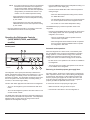 5
5
-
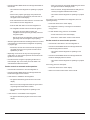 6
6
-
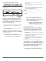 7
7
-
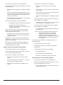 8
8
-
 9
9
-
 10
10
-
 11
11
-
 12
12
-
 13
13
-
 14
14
-
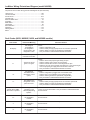 15
15
-
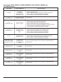 16
16
-
 17
17
-
 18
18
-
 19
19
-
 20
20
-
 21
21
-
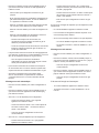 22
22
-
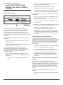 23
23
-
 24
24
-
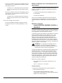 25
25
-
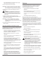 26
26
-
 27
27
-
 28
28
-
 29
29
-
 30
30
-
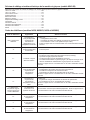 31
31
-
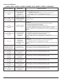 32
32
-
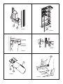 33
33
-
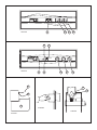 34
34
-
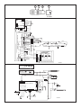 35
35
-
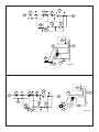 36
36


Norcold N62/N82 Series Le manuel du propriétaire
- Taper
- Le manuel du propriétaire
dans d''autres langues
Documents connexes
-
Norcold N300/ N302 Le manuel du propriétaire
-
-
-
-
-
-
-
-
-