Norcold N64/ N84 Le manuel du propriétaire
- Taper
- Le manuel du propriétaire

WARNING: Improper installation, adjustment, alteration, service or
maintenance can cause personal injury or property damage. Refer
to this manual. For assistance or additional information, contact a
qualied installer, service agency, or the gas supplier.
FOR YOUR SAFETY
Do not store or use gasoline or other ammable vapors and liquid in the
vicinity of this or any other appliance.
FOR YOUR SAFETY
If you smell gas:
1. Open windows
2. Don’t touch electrical switches.
3. Extinguish any open ame.
4. Immediately call your gas supplier.
For N62X and N62XXX models: 6 cu.ft., 2-way, R.V. refrigerators.
For N64X and N64XXX models: 6 cu.ft., 2-way or 3-way, R.V. refrigerators.
For N64XIM and N64XIMXX models: 6 cu.ft., 2-way, R.V. refrigerators with ice maker.
For N82X and N82XXX models: 8 cu.ft., 2-way, R.V. refrigerators.
For N84X and N84XXX models: 8 cu.ft., 2-way or 3-way, R.V. refrigerators.
For N84XIM and N84XIMXX models: 8 cu.ft., 2-way, R.V. refrigerators with ice maker.
The model numbers of 3-way refrigerators include “.3”. The model numbers of 2-way
refrigerators do not.
The letter “X”, in the model numbers above, stands for a letter or a numeral which means a
refrigerator option.
NORCOLD, Inc.
P.O. Box 4248
Sidney, OH 45365-4248
Part No. 635488B (10/15/2012)
English
Owner’s Manual
Norcold Customer Service Dept.
Telephone: 800-543-1219
Fax: 937-497-3183
Web Site: www.norcold.com
WARNING
!

Owner’s Manual 2
Table of Contents
For dened warranty terms, please see the one page warranty statement included in the product information packet.
Safety Awareness .....................................................................................................................................................................................3
Safety Instructions ....................................................................................................................................................................................3
About Your Refrigerator ............................................................................................................................................................................4
Storage volume .................................................................................................................................................................................4
Leveling .............................................................................................................................................................................................4
Operation during travel ......................................................................................................................................................................4
Food compartment ............................................................................................................................................................................4
Freezer compartment ........................................................................................................................................................................4
Crisper(s) ...........................................................................................................................................................................................4
Door bins ...........................................................................................................................................................................................4
Door bin slide (N64X, N64XXX, N64XIM, N64XIMXX, N84X, N84XXX, N84XIM, and N84XIMXX models ) ...................................5
Adjustable shelves ............................................................................................................................................................................5
Door handles .....................................................................................................................................................................................5
Interior light........................................................................................................................................................................................6
Door alarm (N64X, N64XXX, N64XIM, N64XIMXX, N84X, N84XXX, N84XIM, and N84XIMXX models ) .......................................6
Moisture reduction heater..................................................................................................................................................................6
Temperature control system ..............................................................................................................................................................6
Backup operating system ..................................................................................................................................................................6
Temperature switch monitor ..............................................................................................................................................................7
Operating the Refrigerator Controls (N62X, N62XXX, N82X, and N82XXX models) ...............................................................................7
Control panel .....................................................................................................................................................................................7
Automatic mode operation ................................................................................................................................................................8
Removing air from the propane gas supply lines ..............................................................................................................................8
Set the controls to automatic mode operation ...................................................................................................................................9
Set the controls to manual mode operation.......................................................................................................................................9
Operating the Refrigerator Controls (N64X, N64XXX, N64XIM, N64XIMXX, N84X, N84XXX, N84XIM, and N84XIMXX models) .......10
Control panel ...................................................................................................................................................................................10
Automatic mode operation ..............................................................................................................................................................10
Removing air from the propane gas supply lines ............................................................................................................................ 11
Set the controls to automatic mode operation ................................................................................................................................. 11
Set the controls to manual mode operation.....................................................................................................................................12
Effects of HIgh Altitude on Propane Gas Operation ...............................................................................................................................12
Effects of Freezing Temperatures on Refrigerator Operation .................................................................................................................12
Ice Maker (N64X-IM, N64XIMXX, N84X-IM, and N84XIMXX models) ...................................................................................................13
Ice maker operation.........................................................................................................................................................................13
Refrigerator Care Checklist ....................................................................................................................................................................14
Defrosting ...............................................................................................................................................................................................14
Cleaning .................................................................................................................................................................................................15
Interior .............................................................................................................................................................................................15
Drip tray ...........................................................................................................................................................................................15
Metal doors......................................................................................................................................................................................16
Door Sealing ...........................................................................................................................................................................................16
Refrigerator Maintenance Checklist ......................................................................................................................................................16
Refrigerator Storage ...............................................................................................................................................................................17
Ice Maker Storage (N64X-IM, N64XIMXX, N84X-IM, and N84XIMXX models) .....................................................................................17
Refrigerator Maintenance .......................................................................................................................................................................18
Gas ame appearance ....................................................................................................................................................................18
Remove and clean the burner orice ..............................................................................................................................................18
Remove the Refrigerator ........................................................................................................................................................................19
Reinstall the Refrigerator ........................................................................................................................................................................19
Wiring Diagram and Pictorial ..................................................................................................................................................................20
Ice Maker Wiring Pictorial and Diagram (N64X-IM, N64XIMXX, N84X-IM, and N84XIMXX models) ....................................................22
Ice Maker Wiring Pictorial and Diagram (model N843-IM) .....................................................................................................................23
Wiring Diagram and Pictorial - Low Ambient Heater (optional) ..............................................................................................................24
Replacement Parts ................................................................................................................................................................................24
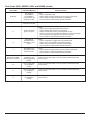
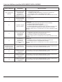
Fault Codes (N62X, N62XXX, N82X, and N82XXX models)..................................................................................................................25
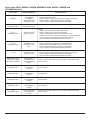
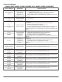
Fault Codes (N64X, N64XXX, N64XIM, N64XIMXX, N84XIM, N84XXX, N84XIM, and N84XIMXX models) ........................................26

Owner’s Manual 3
Safety Instructions
Safety Awareness
Read this manual carefully and understand the contents before you use the refrigerator.
Be aware of possible safety hazards when you see the safety alert symbol on the refrigerator and in this manual. A signal word follows
the safety alert symbol and identies the danger of the hazard. Carefully read the descriptions of these signal words to fully know their
meanings. They are for your safety.
This signal word means a hazard, which if ignored, can cause dangerous personal injury, death, or much
property damage.
This signal word means a hazard, which if ignored, can cause small personal injury or much property
damage.
- The storage of ammable materials behind or around the refrigerator creates a re hazard. Do not use the area
behind the refrigerator to store anything, especially ammable materials (gasoline, cleaning supplies, etc.)
- Do not remove the round ground prong from any of the AC power cords. Do not use a two prong adapter or an
extension cord with any of the AC power cords.
- A circuit overload can result in an electrical re if the wires and/or fuses are not the correct size. Use only the wire
and fuse sizes as writtten in the “Installation Manual”.
- Incorrect installation, adjustment, change to, or maintenance of this refrigerator can cause personal injury, property
damage, or both. Have service and maintenance work done by your dealer or by an Norcold authorized service
center.
- Disconnect both the AC and DC power sources before doing any maintenance work on the refrigerator. All service
work on this refrigerator must be done by a qualied service technician.
- Do not bypass or change the refrigerator’s electrical components or features.
- When you discard an appliance, remove all doors to prevent accidental entrapment and suffocation.
- Do not spray liquids near electrical outlets, connections, or the refrigerator components. Many liquids are electrically
conductive and can cause a shock hazard, electrical shorts, and in some cases re.
- The refrigerator cooling system is under pressure. Do not try to repair or to recharge a defective cooling system. The
cooling system contains sodium chromate. The breathing of certain chromium compounds can cause cancer. The
cooling system contents can cause severe skin and eye burns, and can ignite and burn with an intense ame. Do not
bend, drop, weld, move, drill, puncture, or hit the cooling system.
- At regular intervals, make sure that the refrigerator ue the burner, the vent areas, and the ventilation air pathway
between the vents are completely free from any ammable material or blockage. After a period of storage, it is
especially important to check these areas for any ammable material or blockage caused by animals.
- The rear of the refrigerator has sharp edges and corners. To prevent cuts or abrasions when working on the
refrigerator, be careful and wear cut resistant gloves.
WARNING
!
WARNING
!
CAUTION
!
CAUTION
!

Owner’s Manual 4
About Your Refrigerator
Storage Volume:
This refrigerator is made for storage of foods and frozen food and for making ice.
Total capacity N600 models - 6.3 cubic feet N800 models - 7.5 cubic feet
Leveling:
The refrigerator is made to operate within 3° off level side-to-side and 6° off level front-to-back (as looking at
the front of the refrigerator). Operating it at more than these limits can cause damage to the cooling system
and create a risk of personal injury or property damage. Make sure the vehicle is level before you operate
the refrigerator.
Operation during travel:
While the refrigerator should be level when the vehicle is stopped, performance during travel is not usually effected.
Food compartment:
Start up the refrigerator and let it cool for eight hours before loading with food. If the refrigerator does not start to cool down after about
two hours, contact your dealer or a Norcold authorized service center.
For the best cooling performance:
- Let air move freely inside the entire food compartment.
- Do not cover the shelves with plastic, paper, etc.
To decrease the amount of ice that collects on the cooling ns:
- Cover all liquids and moist foods.
- Let all hot foods cool before putting them in the refrigerator.
- Do not open the door any longer than necessary.
Freezer compartment:
The freezer compartment is made to keep pre-frozen food frozen and not to quick freeze food. Keep pre-frozen foods in the freezer
compartment.
Do not put other items on the ice tray while the water is freezing. The water freezes more rapidly if the thermostat is at
the COLDEST position.
Crisper(s):
The crisper(s) are located at the bottom of the fresh food compartment and supply a storage area to preserve fruit and vegetable
freshness. Make sure that you always push the crispers fully in.
Do not wash the crispers in a dishwasher. The crispers are not dishwasher safe.
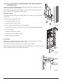
Door bins:
You may put the door bins [52] of the freezer and fresh food compartment in a location that best meets your needs (See Art00989). To
remove the bins, lift them over the locator and pull them forward. To install the bins, push them onto the locator.
Do not wash the door bins and bin slides in a dishwasher. The door bins and bin slides are not dishwasher safe.
CAUTION
!
NOTICE
NOTICE
NOTICE

Owner’s Manual 5
Door bin slide: (N64X, N64XXX, N64XIM, N64XIMXX, N84X, N84XXX, N84XIM, and
N84XIMXX models)
Each door bin includes an adjustable door bin slide [53] to prevent the bin contents from moving
or overturning during transit (See Art00989).
Push each door bin slide against the bin contents. To remove each door bin slide, rotate it out of
the bin. Rotate the each bin slide to into the bin to install.
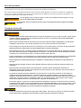
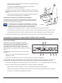
Adjustable shelves:
The shelves in the freezer and the fresh food compartment are made so you can remove them
or move them.
To remove or move the shelf of the freezer:
- Pull the shelf forward out of the slot.
- Push it fully into the slot that you wish.
To remove or move the shelves of the fresh food compartment:
- Remove the screws [41] from the retainer [54] on the side of the refrigerator (See Art00992).
- Remove the retainer.
- Pull each shelf forward out of the slot.
- Push each fully into the slot that you wish.
- Install the retainer with the screws.
Door handles:
During travel, the door latch prevents the door from opening. When closing each door, push the
door toward the refrigerator until you hear a “click” sound.
To open each door, pull the handle away from the refrigerator (See Art00990).
During storage, the storage latch prevents the door from completely closing. Use it to prevent odors
when the refrigerator is stored for an extended period of time.
Art00989
52
53
Art00992
54
41
Art00990

Owner’s Manual 6
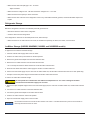
To operate the storage latch (see Art00991), open each door about 1/2 inch, hold the door
handle in the open position, and push the storage latch [55] into the cutout [56] of the strike
plate. Do not use the storage latch as a travel latch because the doors will not be fully closed.
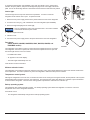
Interior light:
The interior light is at the top of the fresh food compartment. It comes on when the
refrigerator is ON and the door is open. To replace the bulb:
1. Remove the DC power supply wires from the power board at the rear of the refrigerator.
2. To remove the cover [57] , push it toward the rear of the refrigerator (See Art00988).
3. Remove the light bulb [58] from the holder [59].
Use only a GE#214-2 bulb as the replacement bulb. This bulb is available
at most retail automotive parts centers.
4. Install the replacement bulb.
5. Install the cover.
6. Connect the DC power supply wires to the power board at the rear of the refrigerator.
Door alarm:
(N64X, N64XXX, N64XIM, N64XIMXX, N84X, N84XXX, N84XIM, and
N84XIMXX models)
The refrigerator has an alarm to alert you if the fresh food compartment door is not closed.
The refrigerator continues to operate, but if the fresh food compartment door is open and
the interior light remains on for two minutes:
- An audible alarm starts.
- “dr” appears in the center display.
- The interior light automatically turns off.
Close the door to silence the alarm.
Moisture reduction heater:
The refrigerator has a heater that prevents moisture from forming on the center divider between the doors of the freezer and the fresh
food compartment. The heater operates only when the refrigerator is ON and the DC power is sufcient.
Temperature control system:
Although the refrigerator is not frost -free, it is made to limit frost on the cooling ns. At regular intervals, the temperature control system
automatically melts most of the frost from the cooling ns. The water from the cooling ns drains into a collection cup that is attached
to the back of the refrigerator. The heat of the cooling system evaporates the water from the collection cup.
Backup operating system:
This refrigerator has a backup operating system. The backup operating system allows the regerator to continue to cool if the
temperature sensor of the refrigerator should fail.
If this failure occurs:
- The refrigerator automatically changes to the backup operating system.
Art00991
55
56
Art00988
57
58
59
NOTICE

Owner’s Manual 7
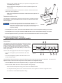
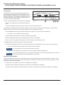
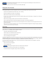
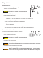
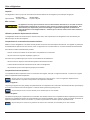
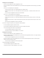
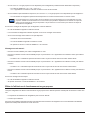
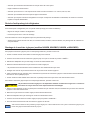
Control panel:
The refrigerator control panel (see Art01019) is between the freezer
compartment and the fresh food compartment. A 12 volt DC power
supply is necessary for the control functions of the refrigerator
to operate. The refrigerator receives DC power from the 12 volt
system of the vehicle; either an auxiliary battery, a converter, or the
vehicle engine battery.
The ON / OFF button [30] starts and shuts down the refrigerator:
- To turn on the refrigerator, push and release the ON / OFF
button.
- To turn off the refrigerator, push the ON / OFF button for one
second and then release.
The TEMP SET button [32] controls the temperature adjustment of the freezer and the fresh food compartment. The temperature
adjustment that you select does not change if the mode of operation of the refrigerator changes.
- Push the TEMP SET button and the temperature setting “1-9” appears in the center display [33].
- Push and hold the TEMP SET button and the temperature setting changes.
- When the desired temperature setting shows, release the TEMP SET button.
- The temperature setting shows for ten seconds and then the current operation mode of the refrigerator shows.
- The number “9” is the coldest temperature setting.
- When you push the TEMP SET button, the temperature setting ashes in the
center display for ten seconds.
- After the temperature setting ashes, the mode of operation appears in the
center dispaly.
- The backup operating system can overfreeze or thaw the contents of the freezer
and the fresh food compartment.
- Make sure the temperatures of the freezer and the fresh food compartment are
satisfactory.
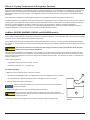
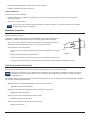
Temperature switch monitor:
The refrigerator is equipped with a temperature switch [142] for overheating protection
(See Art01869) . A Norcold authorized service technician can determine if this switch
has been triggered.
If you open the door(s) too often, the temperatures inside the freezer
and fresh food compartment do not become stable. Allow the
refrigerator to operate for about one hour after each adjustment change
before you examine the contents. The number “9” is the coldest
temperature setting.
- If the temperature is too warm, push and hold the TEMP SET button to raise the temperature setting by one number.
- If the temperature is too cold, push and hold the TEMP SET button to lower the temperature setting by one number.
- Have the refrigerator serviced by your dealer or a Norcold authorized Service Center as soon as possible.
Art01869
142
AC
AUTO
1-COLD
LP GAS TEMP
SET
ON
OFF
MODE
Art01019
30
32
31
34
33
35
36
COLDEST-9
Operating the Refrigerator Controls
(N62X, N62XXX, N82X, and N82XXX models)
NOTICE

Owner’s Manual 8
The MODE button [31] controls the operation mode of the refrigerator.
- Push and hold the MODE button and a light bar shows in the center display beside each of the operating modes of the refrigerator,
one at a time.
- There is one automatic mode of operation and two manual modes of operation.
- When the light bar shows beside the mode of operation that you choose, release the MODE button to operate the refrigerator
in that mode.
Automatic mode operation:
When the refrigerator is in AUTO mode, it automatically uses the most efcient energy source that is available for operation. During
operation, if a more efcient energy source becomes available, the refrigerator controls change from the current energy source to the
more efcient energy source as follows:
- The rst choice is AC operation if 120 volts AC is available to the refrigerator.
- The second choice is propane gas operation if 120 volts AC is not available to the refrigerator.
Removing air from the propane gas supply lines:
For safety reasons, the burner is made to ignite on propane gas within a specied amount of time. When starting the refrigerator for
the rst time, after storage, or after replacing propane gas tank, the propane gas supply lines can have air in them. Due to the air in the
gas supply lines, the burner may not ignite on propane gas within the specied amount of time.
To remove the air from the propane gas supply lines:
- Make sure that all of the gas valves are open.
- Push the ON / OFF button to turn the refrigerator on.
- Push and hold the MODE button until the light bar beside LP GAS shows.
- This means that the refrigerator is operating on propane gas.
- If the air in the propane gas supply lines prevents the burner from ignition on propane gas, the fault code “F” will appear in the
center display.
- Push and hold the ON / OFF button for one second and then release to turn the refrigerator off.
- Push the ON / OFF button to turn the refrigerator on.
- The refrigerator will start a 30 second trial for ignition.
- During the 30 second trial for ignition, the refrigerator controls open the gas safety valve and the igniter sparks.
- After 30 seconds, the refrigerator controls closes the gas safety valve and the igniter stops sparking.
- When the light bar beside the LP GAS [6] shows and no fault code remains, this means that the refrigerator is operating on propane
gas.
- At this time, all of the air is removed from the propane gas supply lines and you may select AUTO mode of operation if you
wish.
- Depending on how much air may be in the propane gas supply lines, you may need to repeat the 30 second trial for ignition two or
three times.
- If the burner does not ignite on propane gas after two or three attempts, stop and consult your local dealer or an authorized
Norcold Service Center.

Owner’s Manual 9
Set the controls to automatic mode operation:
- Push the ON / OFF button to turn the refrigerator on.
- Push and hold the MODE button until the light bar shows beside AUTO [34] and then release.
- If 120 volts AC is available to the refrigerator:
- The light bar beside AC [4] also shows in the center display.
- After ten seconds, the light bar beside AC goes off and only the light bar beside AUTO remains.
- This means that the refrigerator is operating on AC electric.
- If 120 volts AC is not available to the refrigerator:
- The light bar beside AC [35] also shows in the center display.
- After a few seconds, the light bar beside AC goes off and the light bar beside LP GAS [36] shows.
- After 10 seconds, the light bar beside LP GAS goes off and only the light bar beside AUTO remains.
- This means that the refrigerator is operating on propane gas.
If an energy source is available to the refrigerator, but is not operating correctly:
- A fault code shows in the center display.
- The refrigerator controls try to change to a less efcient energy source.
- If a less efcient energy source is not available:
- A fault code shows in the center display.
- Refer to the “Fault Codes” section of this manual.
Set the controls to manual mode operation:
- Push the ON / OFF button to turn the refrigerator on.
- Push and hold the MODE button until the light bar shows beside AC [35] and then release.
- This means that the refrigerator is operating on AC electric.
- Push and hold the MODE button until the light bar shows beside LP GAS [36] and then release.
- This means that the refrigerator is operating on propane gas.
If the energy source is interrupted:
- A fault code shows in the center display.
- Refer to the “Fault Codes” section of this manual.

Owner’s Manual 10
Operating the Refrigerator Controls
(N64X, N64XXX, N64XIM, N64XIMXX, N84X, N84XXX, N84XIM, and N84XIMXX models)
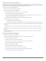
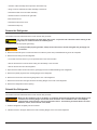
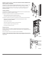
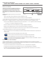
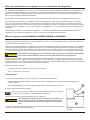
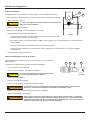
Control panel:
The refrigerator control panel (See Art01018) is between the
freezer compartment and the fresh food compartment. A 12 volt
DC power supply is necessary for the control functions of the
refrigerator to operate. The refrigerator receives DC power from
the 12 volt system of the vehicle; either an auxiliary battery, a
converter, or the vehicle engine battery.
The ON / OFF button [30] starts and shuts down the refrigerator:
- To turn on the refrigerator, push and release the ON / OFF
button.
- To turn off the refrigerator, push the ON / OFF button for one second and then release.
The TEMP SET button [32] controls the temperature adjustment of the freezer and the fresh food compartment. The temperature
adjustment that you select does not change if the operation mode of the refrigerator changes.
- Push the TEMP SET button and the temperature setting (the numbers “1-9”) show in the center display [33].
- The number “9” is the coldest temperature setting.
- Push and hold the TEMP SET button and the temperature setting changes.
- Release the TEMP SET button when the temperature setting that you wish appears.
- After ten seconds, the temperature setting will go out and only a green power ON light remains.
The MODE button [31] controls the operation mode of the refrigerator:
- Push and hold the MODE button and each of the operating modes of the refrigerator show one at a time in the center display.
- There is one automatic mode of operation and two manual modes of operation.
On 3-way models, there are three manual modes of operation.
- When the mode of operation that you wish shows in the center display, release the MODE button.
If you should forget in what mode your refrigerator is operating, push and release the MODE button to show the
current mode of operation in the center display for 10 seconds.
Automatic mode operation:
When the refrigerator is in AUTO mode, it automatically uses the most efcient energy source that is available for operation. During
operation, if a more efcient energy source becomes available, the refrigerator controls change from the current energy source to the
more efcient energy source as follows:
- The rst choice is AC operation if 120 volts AC is available to the refrigerator.
- The second choice is propane gas operation if 120 volts AC is not available to the refrigerator.
- The third choice is DC operation (on 3-way models only) if neither 120 volts AC nor propane gas is available to the refrigerator.
ON
TEMP
SET
MODE
ON-OFF
1-COLD COLDEST-9
Art01018
30
3132
33
NOTICE
NOTICE

Owner’s Manual 11
Removing air from the propane gas supply lines:
For safety reasons, the burner is made to ignite on propane gas within a specied amount of time. When starting the refrigerator for
the rst time, after storage, or after replacing propane gas tank, the propane gas supply lines can have air in them. Due to the air in the
gas supply lines, the burner may not ignite on propane gas within the specied amount of time.
To remove the air from the propane gas supply lines:
- Make sure that valve of the propane gas tanks(s) is open.
- Push the ON / OFF button to turn the refrigerator on.
- Push and hold the MODE button until the letters “LP” show in the center display.
- This means that the refrigerator is operating on propane gas.
- If the air in the propane gas supply lines prevents the burner from ignition on propane gas, the fault codes “no” and then “FL”
will appear in the center display and you will hear an alarm sound.
- Push and hold the ON / OFF button for one second and then release to silence the alarm.
- Push the ON / OFF button to turn the refrigerator on.
- The refrigerator will start a 30 second trial for ignition.
- During the 30 second trial for ignition, the refrigerator controls open the gas safety valve and the igniter makes sparks.
- When no fault code shows and only the power indicator remains, this means that the refrigerator is operating on propane gas in the
manual mode.
- At this time, all of the air is removed from the propane gas supply lines and you may select AUTO mode of operation if you
wish.
- Depending on how much air may be in the propane gas supply lines, you may need to repeat the 30 second trial for ignition two or
three times.
- If the burner does not ignite on propane gas after two or three attempts, stop and consult your local dealer or an authorized
Norcold Service Center.
Set the controls to automatic mode operation:
- Push the ON / OFF button to turn the refrigerator on.
- Push and hold the MODE button until the letters “AU” show in the center display and then release.
- If 120 volts AC is available to the refrigerator:
- The letters “AU” and then “AC” show in the center display.
- After ten seconds, the “AU” and then “AC” go off and only a green power ON light remains.
- This means that the refrigerator is operating on AC electric.
- If 120 volts AC is not available to the refrigerator:
- The letters “AU” and then “AC” show in the center display.
- After ve seconds, the “AU” and then “LP” show in the center display.
- After ten seconds, the “AU” and the “LP” go off and only a green power ON light remains.
- This means that the refrigerator is operating on propane gas.

Owner’s Manual 12
- On 2-way models only, if neither 120 volts AC nor propane gas is available to the refrigerator:
- The fault codes “no” “AC” and then “no” “FL” show in the center display and an audible alarm sounds.
- On 3-way models only, if neither 120 volts AC nor propane gas is available to the refrigerator:
- The refrigerator control will automatically change to DC electric operation.
DC electric operation is less efcient than AC electric and propane gas. Use DC electric operation only to
maintain the refrigerator temperature while in transit and if the other energy sources are not available. Do not
use DC electric to initially decrease the temperature of the refrigerator.
If an energy source is available to the refrigerator, but is not operating correctly:
- A fault code shows in the center display.
- The refrigerator controls try to change to a less efcient energy source.
- If a less efcient energy source is not available:
- An audible alarm starts.
- A fault code shows in the center display.
- Refer to the “Fault Codes” section of this manual.
Set the controls to manual mode operation:
- Push the ON / OFF button to turn the refrigerator on.
- Push and hold the MODE button until the letters “ AC” show in the center display and then release.
- After ten seconds, the “AC” goes off and only a green power ON light remains.
- Push and hold the MODE button until the letters “LP” show in the center display and then release.
- After ten seconds, the “LP” goes off and only a green power ON light remains.
- Push and hold the MODE button until the letters “ dC” show in the center display and then release.
- After ten seconds, the “dC” goes off and only a green power ON light remains.
If the energy source is interrupted:
- A fault code shows in the center display.
- Refer to the “Fault Codes” section of this manual.
Effects of High Altitude on Propane Gas Operation
When you operate the refrigerator on propane gas at altitudes higher than 5500 feet above sea level:
- You may experience reduced cooling performance of the refrigerator.
- You may experience burner outages.
To avoid these possible problems, Norcold recommends that you operate the refrigerator on AC when at altitudes higher than 5500 feet
above sea level.
NOTICE

Owner’s Manual 13
The ice maker is assembled to the refrigerators at the factory as optional equipment. If the refrigerator does not have a factory installed
ice maker, one can not be added to the refrigerator at a later time.
The ice maker is fully automatic and will operate in ambient temperatures as low as 0° F. To allow operation at temperatures between
0° F. and 32° F., the ice maker has a heater on the solenoid water valve and on the water line between the solenoid water valve and the
ice maker.
The water line heater does not protect the water supply line from the vehicle shut off valve to the solenoid
water valve on the back of the refrigerator.
When the freezer temperature of the refrigerator is low enough, the ice maker opens the water solenoid valve and lls the mold. The
ice maker ejects the frozen ice into a storage bin. As the storage bin lls, the ice raises the shut-off arm until it turns off the ice maker.
As you use the ice and lower the ice level in the storage bin, the shut-off arm also lowers. This turns the ice maker on and begins the
process of making ice.
The ice maker operates on:
- Cold potable water at a pressure of 15 psi - 125 psi.
- 120 Volts AC (108 VAC min. - 132 VAC max.).
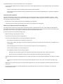
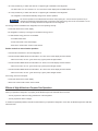
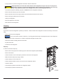
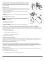
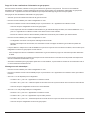
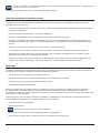
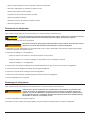
Ice maker operation:
1. Make sure the ice maker AC power connection is secure.
- On N64X-IM and N84X-IM models, the refrigerator AC power cord supplies AC to the ice maker.
- On model N843-IM, a seperate (white) AC power cord supplies AC to the ice maker.
2. Open the water shut off valve of the vehicle.
Make sure that the ice maker arm can move freely and does not touch the frozen
foods in the freezer.
3. Push the ice maker arm down to the ON position [60] (See Art01015).
If you operate the refrigerator without connecting the water supply line and/or
opening the water shut off valve of the vehicle, make sure the ice maker arm is up
in the OFF position.
4. Allow the freezer to cool enough and ice production will begin to ll the storage bin [61].
Ice Maker (N64XIM, N64XIMXX, N84XIM, and N84XIMXX models)
Art01015
60
62
61
Effects of Freezing Temperatures on Refrigerator Operation
A gas absorption refrigerator is not designed to operate in freezing temperatures. If the refrigerator is not equipped for low temperature
operation, and if the cooling system of the refrigerator is exposed to temperatures of 32° F. or lower for an extended period of time,
the refrigerator operation may be disrupted. The refrigerator operation will resume when the cooling system of the refrigerator warms
sufciently.
If the refrigerator is equipped for low temperature operation, the refrigerator will operate in temperatures down to 0° F.
Disrupted operation of the refrigerator, due to extended exposure to temperatures of 32° F. or lower, and any costs incurred to warm the
cooling system of the refrigerator are not covered by the Norcold limited warranty. Please contact your local RV dealer for information
about how to resume refrigerator operation or about how to equip your refrigerator for operation in freezing temperatures.
Do not change the installation or the venting of your refrigerator. Refrigerator failures, which are the result of changes to either the
refrigerator installation or to the venting, are not covered by the Norcold limited warranty.
CAUTION
!
CAUTION
!
NOTICE

Owner’s Manual 14
Refrigerator Care Checklist
Your refrigerator will give you years of trouble free service if you do these simple checks every three to six months:
- Keep the food compartment and the freezer clean. See “Cleaning”.
- Defrost the refrigerator as necessary. See “Defrosting”.
- Make sure the door seals correctly. See “Door Sealing“.
- Be aware of any cooling changes that are not because of weather, loading, or gas control changes. If changes occur, contact your
dealer or service center.
- Make sure the gas supply is propane gas only and not butane or a butane mixture.
- When in propane gas operation, examine the appearance of the ame. See “Gas Flame Appearance”.
- Make sure the air ow in the lower intake vent, through the refrigerator coils and condenser, and out the upper exhaust vent is not
blocked or decreased.
- Make sure the area behind the refrigerator is clear. Do not use the area behind the refrigerator for storage of anything, especially
gasoline and other ammable vapors and liquids.
Defrosting
The cooling ns of the refrigerator operate at below freezing temperature and will naturally form frost from humidity, which is always
present in the air. The humidity inside the refrigerator increases:
- with higher outside temperature and humidity.
- with the storage of non-sealed fresh foods or warm foods.
- with the amount of time that the door(s) are open.
- with any air leakage into the refrigerator.
Although the refrigerator is not frost -free, it is made to limit frost on the cooling ns. At regular intervals, the temperature control system
automatically melts most of the frost from the cooling ns. The water from the cooling ns drains into a collection cup that is attached to
the back of the refrigerator. The heat of the cooling system evaporates the water from the collection cup.
It is normal for frost to collect inside the freezer. Excess frost decreases the cooling performance of the refrigerator. Defrost the
refrigerator and freezer as necessary:
- Remove all food from the refrigerator.
- Turn the refrigerator OFF.
Defrosting the refrigerator makes excess water inside the refrigerator.
- Remove the drain hose from the drip cup at the rear of the refrigerator.
- Put the drain hose into a half-gallon or larger container to capture water.
New plumbing connections and/or impurities in the water supply line after winterizing can cause the rst ice to be
discolored or have an odd avor.
5. To stop the ice maker, push the ice maker arm up to the OFF position [62].
NOTICE
NOTICE

Owner’s Manual 15
- Put dry towels (etc.) inside the refrigerator and freezer to absorb melted frost.
High temperatures can cause the inside surfaces of the refrigerator to warp or melt. Do not use pans of
HOT water, a hair dryer, or any other high temperature devices to defrost the refrigerator. Do not use any
hard or sharp objects to remove frost. Damage to the interior of the refrigerator can occur.
- To increase the speed of defrosting, put pans of WARM water in the refrigerator and freezer.
- Remove the wet towels (etc.) and dry the interior.
- Remove the drain hose from the large container and put the drain hose back into the drip cup.
- Remove the large container from the enclosure.
- Start up the refrigerator.
- Allow the refrigerator to cool down.
- Return all food to the refrigerator.
Cleaning
Interior:
A good time to clean the refrigerator is just after you defrost it. Clean the inside of the refrigerator as often as necessary to avoid food
odors:
- Remove all food from the refrigerator.
Do not use abrasive cleaners, chemicals, or scouring pads because they can damage the interior of the refrigerator.
- Wash the interior with a mild cleaner or a solution of liquid dish detergent and warm water.
- Rinse with a solution of baking soda and clean water.
- Dry with clean cloth.
- Put all food in the refrigerator.
Drip tray:
To remove and clean the drip tray:
- Remove the screws [41] from the retainer [54] on the side of the refrigerator (See Art00992).
- Remove the retainer.
- Pull the self that is in front of the drip tray forward to remove from the refrigerator
- Make sure that the drip tray is empty of water.
- Pull the drip tray out of the drain hose.
- Pull the drip tray forward to remove from the slots in the refrigerator cabinet.
- Clean the drip tray.
- Push the drip tray back into the slots in the refrigerator cabinet.
- Push the drip tray back into the drain hose.
Art00992
54
41
NOTICE
CAUTION
!

Owner’s Manual 16
Refrigerator Maintenance Checklist
Read and understand the following maintenance sections of this manual.
Norcold is not responsible for installation, adjustment, alteration, service, or maintenance performed by anyone other
than a qualied RV dealer or a Norcold authorized service center.
Have a qualied RV dealer or a Norcold authorized service center do these annual safety and maintenance checks:
- Examine the gas supply lines for leaks.
- Replace or repair if needed.
- Make sure the propane gas pressure is 11 inches of water column.
- Adjust if needed.
- Make sure the combustion seal is complete and intact.
- Replace or repair it if needed.
- Make sure the burner and the burner orice are clean.
- Clean if needed.
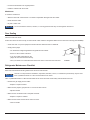
Door Sealing
Check the seal of the doors.
If either door does not seal correctly, excess frost will collect inside the refrigerator. Make sure the doors seal correctly (See Art00980):
- Close each door on a piece of paper that is about the size and thickness of a dollar bill.
- Gently pull the paper.
- You should feel a slight drag between the gasket and the cabinet.
- Do this on all four sides of the door.
- If you do not feel a slight drag on the
paper, the door does not seal correctly.
- Have your dealer or an authorized Norcold Service Center correct the seal of the door.
- Put the wire shelf back in the original position.
- Install the retainers with the screws.
Metal doors:
To clean the metal doors:
- Wash the doors with a mild cleaner or a solution of liquid dish detergent and warm water.
- Rinse with clean water.
- Dry with a clean cloth.
Do not use abrasive cleaners, chemicls, or scouring pads because they can damage the metal doors.
Art00980
NOTICE
NOTICE

Owner’s Manual 17
Refrigerator Storage
Before the refrigerator is stored for an extended (seasonal) period of time:
- Defrost and clean the interior of the refrigerator.
- Close the doors with the storage latch.
If the refrigerator is stored for an extended period of time, before start up:
- Make sure there are no obstructions in the vents, the ventilation air pathway, the burner, the orice, or the ue area.
To prepare the ice maker for seasonal storage:
1. Close the vehicle water supply valve to the ice maker.
2. Push the ice maker arm up until it locks into the OFF position.
3. Remove the garden hose adapter from the water solenoid valve.
4. Remove the ice maker water line from the water solenoid valve
- Do not unwrap the water line heater wires from around the water solenoid valve.
5. Drain all of the water from both the water supply line and the ice maker water line.
6. Put the end of the water supply line, the end of the ice maker water line, and the water solenoid valve each into a clean plastic bag.
7. Use tape to close each plastic bag around the water lines and the water solenoid valve.
To use the ice maker after seasonal storage:
Do not operate the ice maker when the ambient air temperature is 0° F. or lower. Damage to the water
solenoid valve and the water supply line can occur.
1. Remove the tape and plastic bags from the end of the water supply line, the end of the ice maker water line, and the water solenoid
valve.
2. Connect the ice maker water line to the water solenoid valve.
3. Connect the garden hose adapter to the water solenoid valve.
4. Push the ice maker arm down into the ON position.
5. Open the vehicle water supply valve to the ice maker.
You should discard and not use the rst two batches of ice cubes. It will take about three cycles for the ice maker to
make fully formed and clean ice cubes.
Ice Maker Storage (N64XIM, N64XIMXX, N84XIM, and N84XIMXX models)
- Make sure the electrode spark gap is 1/8 - 3/16 inch.
- Adjust if needed.
- Make sure the AC voltage is 108 - 132 volts and the DC voltage is 10.5 - 15.4 volts.
- Make sure the thermocouple tip is clean and secure.
- Make sure the area at the rear of the refrigerator is free of any combustible materials, gasoline, and other ammable vapors and
liquids.
CAUTION
!
NOTICE

Owner’s Manual 18
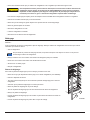
Refrigerator Maintenance
Gas ame appearance:
While in GAS operation, examine the appearance of the gas ame:a
- Turn the gas control to the COLDEST position.
- Open the lower intake vent.
The burner box cover can be hot. Wear gloves to avoid burns.
- Remove the drip cup by removing the screw.
- Remove the burner box cover by removing the screw.
- Look at the gas ame [75] (See Art01605).
- The ame should be:
- a darker blue color on the inside of the ame and a lighter blue color on the outside of the ame.
- a constant shape without ickering.
- Contact your dealer or Norcold authorized service center if the ame is:
- yellow
- ickering or changing shape.
- Make sure the ame does not touch the inside of the ue tube [76].
- If the ame touches the inside of the ue tube, contact your dealer or Norcold authorized service center.
- Close the burner box door.
Remove and clean the burner orice:
Your dealer or Norcold authorized service center must do this procedure.
Remove and clean the burner orice (See Art00956):
- Close the valve at the propane gas tank(s).
- Push the ON / OFF button to shut down the refrigerator.
The burner box cover can be hot. Wear gloves to avoid burns.
- Open the lower intake vent.
- Remove the drip cup by removing the screw.
- Remove the burner box cover by removing the screw.
To avoid possible propane gas leaks, always use two wrenches to loosen and tighten the gas supply line
connections.
- Remove the are nut from the orice assembly [77] (See Art00956).
- Remove the orice assembly from the burner [78].
Do not try to remove the orice [79] from the orice adapter [80] when cleaning. Removal will damage
the orice and seal of the orice and can cause a propane gas leak. Leaking propane gas can ignite or
explode which can result in dangerous personal injury or death. Do not clean the orice with a pin or
other objects.
Art 00956
77
78
79
80
75
76
Art01605
CAUTION
!
CAUTION
!
WARNING
!
WARNING
!

Owner’s Manual 19
Remove the Refrigerator
Your dealer or Norcold authorized service center must do this procedure.
The rear of the refrigerator has sharp edges and corners. To prevent cuts or abrasions when working on the
refrigerator, be careful and wear cut resistant gloves.
1. Close the valve at the propane gas tank(s).
To avoid possible propane gas leaks, always use two wrenches to loosen and tighten the gas supply line
connections.
2. Remove the black AC power cord and the white ice maker AC power cord (model N843-IM only) from the receptacle.
3. Remove the DC wiring from the refrigerator:
- Put a mark on the DC wires so you can put them back in the correct location.
- Remove the DC fuse or remove the DC wiring from the battery or the converter.
- Remove the DC wires from the refrigerator.
4. Open the lower intake vent and remove the gas supply line from the bulkhead tting of the refrigerator.
5. Remove the plastic plugs from the mounting anges of the refrigerator.
6. Remove the screws from the mounting ange at the rear of the refrigerator.
7. Remove the screws from the upper and lower mounting anges on the front of the refrigerator.
8. Remove the refrigerator from the opening.
- Clean the orice assembly with air pressure and alcohol only.
- Using a wrench, assemble the orice assembly to the burner.
- Assemble the are nut to the orice assembly.
- Examine all of the connections for gas leaks.
- Clean the burner box.
- Assemble the burner box cover.
- Assemble the drip cup.
Reinstall the Refrigerator
Your dealer or Norcold authorized service center must do this procedure.
Make sure the combustion seal is not broken, is completely around the refrigerator mounting anges, and
is between the mounting anges and the wall of the enclosure. If the combustion seal is not complete,
exhaust fumes can be present in the living area of the vehicle. The breathing of exhaust fumes can cause
dizziness, nausea, and in extreme cases, death.
1. Push the refrigerator completely into the enclosure.
2. Install the screws in the upper and then the lower mounting anges on the front of the refrigerator.
WARNING
!
CAUTION
!
WARNING
!

Owner’s Manual 20
3. Install the screws in the mounting ange at the rear of the refrigerator.
4. Put the plastic plugs into the mounting anges of the refrigerator.
To avoid possible propane gas leaks, always use two wrenches to loosen and tighten the gas supply line
connections.
5. Attach the gas supply line to the bulkhead tting of the refrigerator.
6. Open the valve at the propane gas tank(s).
Do not allow the leak checking solution to touch the electrical components. Many liquids are electrically
conductive and can cause electrical shorts and in some cases, re.
7. Examine the gas supply line for leaks.
8. Connect the DC wiring to the refrigerator:
- Connect the DC wires to the refrigerator.
- Install the DC fuse or connect the DC wiring to the battery or the converter.
9. Connect the black AC power cord and the white ice maker AC power cord (model N843-IM only) to the receptacle.
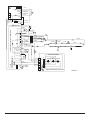
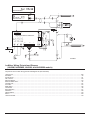
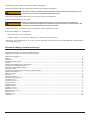
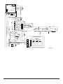
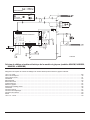
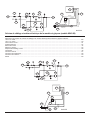
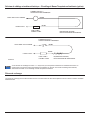
Wiring Diagram and Pictorial
The parts in the wiring pictorial are (See Art01875):
The parts in the wiring diagram are (See Art01876):
AC heater .................................................................................................................................................................................................A
Light ......................................................................................................................................................................................................... B
Thermister ............................................................................................................................................................................................... C
Gas valve................................................................................................................................................................................................. D
Igniter....................................................................................................................................................................................................... E
Divider heater ...........................................................................................................................................................................................F
Temperature switch (optional) ................................................................................................................................................................. G
Temperature switch (optional) ................................................................................................................................................................. H
Fan (optional) ............................................................................................................................................................................................I
Ice maker water line heater (optional) ......................................................................................................................................................J
DC heater (optional) ................................................................................................................................................................................ K
Chassis ground.........................................................................................................................................................................................L
DC board (optional) .................................................................................................................................................................................M
Door switch .............................................................................................................................................................................................. N
Temperature switch ..................................................................................................................................................................................P
Switched 12 VDC .....................................................................................................................................................................................1
Fused continuous 12 VDC........................................................................................................................................................................2
Communications .......................................................................................................................................................................................3
Display ground..........................................................................................................................................................................................4
Auxiliary ground ........................................................................................................................................................................................5
Auxiliary +12 VDC ....................................................................................................................................................................................6
Divider +12 VDC .......................................................................................................................................................................................7
Gas valve +12 VDC ..................................................................................................................................................................................8
5 Amp fuse DC .......................................................................................................................................................................................F1
8 Amp fuse AC ........................................................................................................................................................................................F2
30 Amp fuse DC ....................................................................................................................................................................................F3
WARNING
!
WARNING
!
La page est en cours de chargement...
La page est en cours de chargement...
La page est en cours de chargement...
La page est en cours de chargement...
La page est en cours de chargement...
La page est en cours de chargement...
La page est en cours de chargement...
La page est en cours de chargement...
La page est en cours de chargement...
La page est en cours de chargement...
La page est en cours de chargement...
La page est en cours de chargement...
La page est en cours de chargement...
La page est en cours de chargement...
La page est en cours de chargement...
La page est en cours de chargement...
La page est en cours de chargement...
La page est en cours de chargement...
La page est en cours de chargement...
La page est en cours de chargement...
La page est en cours de chargement...
La page est en cours de chargement...
La page est en cours de chargement...
La page est en cours de chargement...
La page est en cours de chargement...
La page est en cours de chargement...
La page est en cours de chargement...
La page est en cours de chargement...
La page est en cours de chargement...
La page est en cours de chargement...
La page est en cours de chargement...
La page est en cours de chargement...
-
 1
1
-
 2
2
-
 3
3
-
 4
4
-
 5
5
-
 6
6
-
 7
7
-
 8
8
-
 9
9
-
 10
10
-
 11
11
-
 12
12
-
 13
13
-
 14
14
-
 15
15
-
 16
16
-
 17
17
-
 18
18
-
 19
19
-
 20
20
-
 21
21
-
 22
22
-
 23
23
-
 24
24
-
 25
25
-
 26
26
-
 27
27
-
 28
28
-
 29
29
-
 30
30
-
 31
31
-
 32
32
-
 33
33
-
 34
34
-
 35
35
-
 36
36
-
 37
37
-
 38
38
-
 39
39
-
 40
40
-
 41
41
-
 42
42
-
 43
43
-
 44
44
-
 45
45
-
 46
46
-
 47
47
-
 48
48
-
 49
49
-
 50
50
-
 51
51
-
 52
52


Norcold N64/ N84 Le manuel du propriétaire
- Taper
- Le manuel du propriétaire
dans d''autres langues
- English: Norcold N64/ N84 Owner's manual
Documents connexes
-
Norcold N64/N84 Le manuel du propriétaire
-
Norcold N300/ N302 Le manuel du propriétaire
-
-
-
Norcold DE-0041/EV-0041 Le manuel du propriétaire
-
-
-
-
-