
FOR YOUR SAFETY
WHAT TO DO IF YOU SMELL GAS
! DO NOT TRY TO LIGHT ANY APPLIANCE.
! DO NOT TOUCH ANY ELECTRIC SWITCH: DO NOT USE ANY PHONE IN YOUR
VEHICLE.
! IMMEDIATELY CALL YOUR GAS SUPPLIER FROM A NEIGHBOR’S PHONE.
FOLLOW THE GAS SUPPLIER’S INSTRUCTIONS.
! IF YOU CANNOT REACH YOUR GAS SUPPLIER, CALL THE FIRE
DEPARTMENT.
FREEZE WARNING
DRAIN HEATER IF SUBJECT TO FREEZING TEMPERATURES.
WARNING: IMPROPER INSTALLATION, ADJUSTMENT, ALTERATION, SERVICE
OR MAINTENANCE CAN CAUSE INJURY OR PROPERTY DAMAGE. REFER TO
THIS MANUAL. FOR ASSISTANCE OR ADDITIONAL INFORMATION, CONSULT A
QUALIFIED INSTALLER, SERVICE AGENCY OR THE GAS SUPPLIER.
FOR YOUR SAFETY
DO NOT STORE OR USE GASOLINE OR OTHER COMBUSTIBLE MATERIALS OR
LIQUIDS NEAR OR ADJACENT TO THIS HEATER OR ANY OTHER APPLIANCE. THIS
APPLIANCE SHALL NOT BE INSTALLED IN ANY LOCATION WHERE FLAMMABLE
LIQUIDS OR VAPORS ARE LIKELY TO BE PRESENT.
AN ODORANT IS ADDED TO THE GAS USED BY THIS WATER HEATER.
INSTALLER: AFFIX THESE INSTRUCTIONS TO OR ADJACENT TO WATER HEATER.
OWNER: RETAIN THESE INSTRUCTIONS AND WARRANTY FOR FUTURE REFERENCE.
ALL TECHNICAL AND WARRANTY QUESTIONS SHOULD BE DIRECTED TO THE COMPANY
LISTED ON THE WARRANTY, OR RATING PLATE WHICH CAME WITH YOUR WATER HEATER.
SUBURBAN MANUFACTURING COMPANY
676 Broadway Street
Dayton, Tennessee 37321
423-775-2131
www.rvcomfort.com
Part Number 204539
3-24-09
INSTALLATION AND OPERATION
MANUAL
DIRECT VENT
GAS WATER HEATER
MODELS
SW6DEL • SW10DEL • SW12DEL • SW16DEL
FOR INSTALLATION IN RECREATIONAL
VEHICLES AND MOBILE HOUSING

door frame, when installed, must not overlap onto screw or other fastener head.
If due to the wall thickness, it is not possible to secure the water heater without
covering the fastener head with the door frame, it is important to not over tighten
the fastener and distort the control housing. Over tightening of the fastener may
cause water heater leaks between the control housing and the door frame.
NOTE: Caulk around screw or fastener heads to assure water tight seal.
C. Install chocks, one on each side of water heater, as illustrated in Figure 1B.
D. On mesa or yoder type sidewalls, atten the wall area around the opening.
E. Caulk around framed opening (trailer skin) as illustrated.
F. Caulk around door frame using 2 beads of silicone caulking (or suitable
caulking) - one on ange to seal to control housing and one around back side of
frame to seal to coach skin. (See detail A in illustration.)
G. Insert door frame into control housing and secure with three (3) No. 8-15 x
3 1/2” screws provided.
H. To install door, place the two holes in the bottom of the door over the door
pins on the frame. Close the door so that the latch protrudes through the slot in
the door. Turn latch 90 degrees to fasten door.
I. The module board on models SW6DEL, SW10DEL, SW12DEL, SW16DEL
is not secured to the water heater. It is to be permanently mounted by the
installer.
The module board must be mounted to where it is accessible for service yet out
of way of children. It should be located in a place where it cannot be subjected to
moisture, cleaning chemicals, ammable vapors and liquids, etc.
The board and all wiring to the board must be protected in order to prevent
damages and accidental contact with these parts. The module board may be
mounted with two (2) No. 6 x 5/8 screws or other suitable hardware.
INSTALLATION USING HINGED DOOR
(See Figure 3 SW6DEL)
A. Position heater into framed opening as illustrated.
B. On mesa or yoder type sidewalls, atten the wall area around the opening.
C. Caulk around framed opening (trailer skin) as illustrated.
D. Lay a bead of silicone caulking (or suitable caulking) around the inner edge
of the control housing (top, bottom and sides). See detail “A” in illustration. This
will seal frame to control housing.
E. Apply a bead of silicone caulking (or suitable caulking) around back side of
door frame. See detail “A” in illustration. This will seal frame to coach skin.
F. Fit the door frame into control housing (over the caulking already applied) and
pull frame tight to control housing using the three (3) No. 8-15 x 3 1/2” screws
provided.
G. Push water heater into framed opening until back side of door frame (now
attached to control housing) is against the side of the coach and rmly attach
with screws around the perimeter of the frame. NOTE: The two (2) holes in
bottom of frame identied as “A” in Figure 3 are also used to mount door hinge
to the frame.
H. Install chocks, one on each side of water heater, as illustrated in Figure 1A.
I. Attach door to frame as illustrated.
J. Close the door so that the door latch protrudes through the slot in the door.
Turn latch 90 degrees to fasten door.
K. The module board on models SW6DEL, is not secured to the water heater.
It is to be permanently mounted by the installer.
The module board must be mounted to where it is accessible for service yet out
of way of children. It should be located in a place where it cannot be subjected
to moisture, cleaning chemicals, ammable vapors and liquids, etc.
The board and all wiring to the board must be protected in order to prevent
damages and accidental contact with these parts. The module board may be
mounted with two (2) No. 6 x 5/8 screws or other suitable hardware.
INSTALLATION REQUIREMENTS
WARNING! Installation of this appliance must be made in accordance
with the written instructions provided in this manual. No agent,
representative or employee of Suburban or other person has the
authority to change, modify or waive any provision of the instructions
contained in this manual.
CAUTION: If possible, do not install the water heater to where the vent can
be covered or obstructed when any door on the trailer is opened. If this
is not possible, then the travel of the door must be restricted in order to
provide a 6” minimum clearance between the water heater vent and any
door whenever the door is opened.
CAUTION: Due to the differences in vinyl siding, this appliance should not
be installed on vinyl siding without rst consulting with the manufacturer
of the siding or cutting the siding away from the area around the appliance
vent.
CAUTION: In any installation in which the vent of this appliance can be
covered due to the construction of the RV or some special feature of the
RV such as slide out, pop-up etc., always insure that the appliance cannot
be operated by setting the thermostat to the positive “OFF” position and
shutting off all electrical and gas supply to the appliance.
CAUTION: Do not install this appliance to where the vent terminates below
a slide-out. This appliance is not to be installed under any overhang. It
must be free and clear of any type overhang.
This installation must conform with the requirements of the authority having
jurisdiction or in the absence of such requirements with the latest edition of the
National Fuel Gas Code ANSI Z223.1/NFPA 54; and the latest edition of the
American National Standard for Recreational Vehicles-NFPA 1192. In Canada
the installation should conform with the following standards.
A. For installation in Recreational Vehicle
1. Gas - CSA standard CAN/CSA Z240.4.2-08 Installation Requirements for
Propane Appliances and Equipment in Recreations Vehicles.
2. Electrical - CSA standard CAN/CSA 240.6.2/C22.2 No. 148-08 Electrical
Requirements for Recreational Vehicles.
3. Plumbing - CSA standard CSA Z240.3.2 Plumbing Requirements for
Recreational Vehicles.
B. For installation in Mobile Housing
1. Gas - CSA standard CSA Z240.4.1 Installation Requirements for Gas
Burning Appliances and Equipment in Mobile Homes.
2. Electrical - CSA standard CSA C22.1 Canadian Electrical Code Part 1.
3. Plumbing - CSA standard CSA Z240.3.1 Plumbing Requirements for Mobile
Homes.
The appliance shall be disconnected from the gas supply piping system during
any pressure testing of the system.
The appliance and its gas connections shall be leak tested before placing the
appliance in operation.
All air for combustion must be supplied from outside the structure. Air for
combustion must not be supplied from occupied spaces.
INSTALLATION INSTRUCTIONS
Minimum clearance from combustible construction on sides, top, oor and rear =
0 inches. Provide room for access to rear of heater for servicing.
Provide an opening ush with oor in outer wall of coach as shown. Wall of
coach should be framed as shown in Figure 1 SW6DEL; Figure1A SW10DEL/
SW12DEL/SW16DEL. Maintain inside dimensions listed below. Do not install on
carpet unless the carpet is covered by a metal or wood shield covering the entire
area underneath the water heater. If you prefer, you may cut away the carpet
from this area.
INSTALLATION USING FLUSH MOUNT FRAME &
DOOR
(See Figure 2 SW6DEL; Figure 2A SW10DEL, SW12DEL, SW16DEL)
A. Position heater into framed opening as illustrated. Slide unit into opening until
the front of the control housing is ush with the exterior coach skin.
B. Secure the control housing to the coach wall (framed opening) at the top and
sides of control housing compartment using screws or other suitable fasteners.
Recess the screws or fasteners back far enough from the front edge of control
housing (approximately 1 1/2”) in order to clear the ange on door frame. The
2

FLOORING
FRAMING
INNER COACH WALL
OUTER COACH WALL
B
A
A=12 3/4"+1/8"-0"
B=12 3/4"+1/8"-0"
Figure 1
INNER COACH WALL
OUTER COACH WALL
FRAMING
FLOORING
A = 16 3/8"±1/16"
B = 16 3/8"±1/16"
Figure 1A
WATER HEATER AS VIEW FROM INSIDE R.V.
SECURE CHOCKS, ONE ON EACH SIDE, TIGHTLY AGAINST WATER HEATER JACKET
AND FASTEN TO VEHICLE FLOOR TO PREVENT MOVEMENT. CHOCKS SHOULD BE
APPROXIMATELY 2" X 2" X 6"
FRAMED OPENING
FLOOR
Figure 1B
3

SW6DEL
Figure 2
SW10DEL
SW12DEL
SW16DEL
Figure 2A
4

MAKING WATER CONNECTIONS
A. Water connections are made at the rear of the water heater. See Figure 4.
Connect the hot and cold water lines to the 1/2” female pipe tting provided on
rear of tank. These ttings are marked “HOT” and “COLD”. NOTE: Inside each
tting is a plastic ll tube. Its purpose is to enhance water circulation. DO NOT
REMOVE PLASTIC FILL TUBE.
IMPORTANT: Use a pipe thread compound suitable for potable water or pipe
thread tape on all connections to assure they will not leak.
B. For ease of removal, it is suggested that a pipe union be installed in each
water line.
C. Fill tank with water. Open both hot and cold water faucets to expel air from
tank. When tank is lled and water ows from faucets, close both faucets and
check all connections for leaks.
CAUTION: If you use air pressure to check for leaks, the pressure must not
exceed 30 PSI (in accordance with NFPA 1192).
NOTE: After leak testing, drain water from tank.
MAKING GAS CONNECTIONS
A. Connect a 3/8” gas supply line to the 3/8 are tting at gas valve located in
the control housing. When making the gas connection, hold the gas tting on the
valve with a wrench when tightening the are nut. Failure to hold tting secure
could result in a gas leak due to tting being damaged.
NOTE: It will be necessary to remove the grommet from the control housing,
make the gas connection at the valve, then reinstall grommet.
WARNING! It is imperative that grommet and gas line through grommet
be caulked air tight. If not tightly sealed, moisture and potential harmful
ue products could vent through opening and into living area of trailer.
(See Figure 5.)
B. Turn on gas and check all ttings and connections for leaks, using a soap and
water solution. Correct even the slightest leak immediately.
WARNING! Do not use an open ame to check for leaks!
HIGH ALTITUDE DERATION
Suburban water heaters are certied by nationally recognized testing laboratories
for operation without modications at altitudes up to 4,500 feet. Operation above
this elevation may require derating by 4 percent for every 1,000 feet above
sea level. For example, at 8,000 feet, the water heater should be derated
approximately 32 percent.
If the unit is not properly derated, lack of sufcient oxygen for combustion
may produce improper burner operation. Pilot outage caused by burner lift-off
or sooting from a yellow burner may occur indicating the possibility of carbon
monoxide. You may also notice a lack of efciency in heating the water because
of incomplete combustion of the burner at these higher altitudes.
Consult with the local gas company, your dealer, an RV service agency or
Suburban Manufacturing Company for proper derating of the unit. Change-
out of the orice (derating) should be done by the dealer or a qualied service
SW6DEL
Figure 3
HOT
COLD
Figure 4
CAULK AND SEAL GROMMET (INCLUDING SLIT
AND TUBING) ALL AROUND AIR TIGHT
GAS VALVE
CONTROL HOUSING
ILLUSTRATED SHOWING
INSIDE OF HOUSING
GROMMET
(GAS INLET)
Figure 5
5

agency.
NOTE: It is important that once the unit has returned to lower elevation (below
4,500 feet), this high altitude deration and pilot adjustments (if equipped) be
reversed for proper operation of the unit.
MAKING ELECTRICAL CONNECTIONS
12 VOLTS D.C.
A. Refer to Figure 2 for location of D.C. junction box SW6DEL.
B. The electrical connections must be made in accordance with local codes and
regulations. In the absence of local codes and regulations, refer to the latest
edition of the National Electrical Code NFPA 70.
In Canada, the electrical installation should conform with CSA standard CAN/
CSA Z240.6.2-08/C22.2 No. 148-08 Electrical Requirements for Recreational
Vehicles and CSA C22.1 Canadian Electrical Code Part 1 when installing the unit
in recreational vehicles and mobile homes respectively.
C. Make the 12 Volt D.C. electrical connections following the wiring diagram
illustrated in Figure 6.
If the power supply is to be from a converter, we recommend that the converter
system be wired in parallel with the battery. This will serve two purposes:
1. Provide a constant voltage supply
2. Filter any A.C. spikes or volt surges
We recommend insulated terminals be used for all electrical connections.
MAKING ELECTRICAL CONNECTIONS
120 VOLTS A.C.
A. Refer to Figure 2 for location of A.C. junction box.
B. The electrical connections must be made in accordance with local codes and
regulations. In the absence of local codes and regulations, refer to the latest
edition of the National Electrical Code NFPA 70.
In Canada, the electrical installation should conform with CSA standard CAN/
CSA Z240.6.2-08/C22.2 No. 148-08. Electrical requirements for Recreational
Vehicles and CSA C22.1 Canadian Electrical Code Part 1 when installing the
unit in recreational vehicles and mobile homes respectively.
C. Check rating plate and wiring diagram (Figure 7) before proceeding. Install a
fused safety switch or circuit breaker of adequate capacity between heater and
electrical power source. Attach the black and white wires from the fused switch
or breaker to corresponding colored wires in heater junction box. A green wire
from a well grounded source must be attached to the green nut in the junction
box.
CAUTION: Before applying the 120 VAC power to the water heater junction
box, be sure the switch for electric element is in the “OFF” position.
WARNING! Before the switch for the electric element is turned to the
“ON” position, the water heater tank must be lled with water. See
“Safety Warnings”.
MAINTENANCE
WARNING! If the user of this appliance fails to maintain it in the
condition in which it was shipped from the factory or if the appliance is
not used solely for its intended purpose or if appliance is not maintained
in accordance with the instructions in this manual, then the risk of a
re and/or the production of carbon monoxide exists which can cause
personal injury, property damage or loss of life.
WARNING: For your safety, all repairs should be performed by your
dealer or a qualied service person.
A. Main Burner: Do not allow the burner to burn with a yellow ame, because
sooting will occur. (See Safety Warnings). If the burner ame is yellow and has
an erratic pattern, shut unit down and contact a qualied service agency. Do not
continue operating unit with improper burner ame. (See Figure 8 for correct and
incorrect burner ame appearance.)
B. Periodically inspect unit for soot. If soot is present anywhere on water heater,
immediately shut unit down and contact your dealer or a qualied service person.
Soot is a sign of incomplete combustion and must be corrected before operating
water heater. Areas to check would include:
1. Check for an obstruction in burner or the ue box.
2. Check the screen in the door to see that no foreign material has accumulated
to prevent ow of combustion and ventilating air.
3. Check to be sure there is no ame present at burner orice or burner
whenever main gas valve is closed. This can be checked by turning the OFF/ON
switch to the “OFF” position.
C. Frequent checks should be made of the grommet on the gas inlet to assure
tight seal. (See “Making Gas Connections”).
D. Periodically check wiring and wire connection to be sure wiring is not damaged/
frayed and that all terminals and connections are tight and in compliance with
codes (See “Making Wire Connections”).
12 V.D.C. ONLY
JUNCTION
BOX
Y
G
BL
R
RED
BLUE
GREEN
YELLOW
BROWNBR
BK
BLACK
G
BL
R
R
Y
BK
1
2
3
4
IF ANY OF THE ORIGINAL WIRE AS SUPPLIED WITH THE WATER
HEATER MUST BE REPLACED, IT MUST BE REPLACED WITH 18 GA.,
105°C WIRE OR IT'S EQUIVALENT.
SWITCH
HI-LIMIT T'STAT
MODULE BD.
SPARK CABLE
ELECTRODE
BR
GAS VALVE
SWITCH
( FACTORY WIRING)
( ---- FIELD WIRING)
DISCONNECT POWER SUPPLY BEFORE SERVICING THERMOSTAT
AND HI-LIMIT UNDER ACCESS COVER.
1 3 4 6
CAUTION: DO NOT HI-POT (DIELECTIC HIGH VOLTAGE TEST) THIS
UNIT AFTER INSTALLATION. TO DO SO MAY CAUSE COMPONENT
DAMAGE AND VOIDS WARRANTY OF WATER HEATER.
*12VDC SIDE OF RELAY 340539
LIGHT
RELAY
O
ORANGE
O
(GAS)
(ELECTRIC)
Figure 6
Figure 7
YELLOW OR YELLOW/
ORANGE
ERRATIC PATTERN
BLUE OR BLUE/ORANGE
WELL DEFINED PATTERN
CORRECT
INCORRECT
Figure 8
6

SAFETY WARNINGS
WARNING! It is imperative that the water heater tank be lled with water
before operating the water heater. Operation of the water heater without
water in the tank may result in damage to the tank and/or controls. This
type of damage is not covered by the limited warranty.
WARNING! Hydrogen gas may result if you have not used this heater
for two weeks or more. HYDROGEN GAS IS EXTREMELY FLAMMABLE.
To reduce the risk of injury under these conditions, open the hot water
faucet for several minutes at the kitchen sink before you use any
electrical appliance connected to the hot water system. If hydrogen is
present, you probably will hear an unusual sound such as air escaping
through the pipe as the water begins to ow.
Hydrogen gas may be present even after water has been drained from
the tank. Open faucet at sink and allow system to vent for several
minutes (5-10 minutes).
Do not smoke or have any open ame near the open faucet. Do not
attempt to light pilot or main burner. On DSI models, be sure the switch
is “OFF”.
Should overheating occur, or the gas supply fail to shut off, shut off
the manual gas valve to the appliance before shutting off the electrical
supply.
Do not use this appliance if any part has been submerged under water.
Immediately call a qualied service technician to inspect the appliance
and to replace any part of the control system and any gas control that
has been submerged under water.
Do not alter the operation of your water heater nor change the design/
construction of your water heater. Accessories are being marketed for
RV products which we do not recommend. For your safety, only factory
authorized parts are to be used on your water heater.
Periodically inspect the vent for obstructions or presence of soot. Soot
is formed whenever combustion is incomplete. This is your visual
warning that the water heater is operating in an unsafe manner. If soot
is present, immediately shut the water heater down and contact your
dealer or a qualied service person.
When considering add-on rooms, porch or patio, attention must be given
to the venting of your water heater. For your safety, do not terminate the
vent on your water heater inside add-on rooms, screen porch or onto
patios. Doing so will result in products of combustion being vented into
the rooms or occupied areas.
Never operate the heater if you smell gas. Do not assume that the smell
of gas in your RV is normal. Any time you detect the odor of gas, it is
to be considered life threatening and corrected immediately. Extinguish
any open ames including cigarettes and evacuate all persons from the
vehicle. Shut off gas supply at LP gas bottle. (See the Safety notice on
front cover of this manual.)
NOTE: Always open both the cold and hot water faucets when lling vehicle
water tank to allow air pockets to be forced out of the water heater. When water
ows from the heater faucets, close both faucets.
WARNING! Do not store or use combustible materials or liquids near
or adjacent to this heater. The appliance shall not be installed in any
location where ammable liquids or vapors are likely to be present.
Be sure the power is “OFF” to the water heater ignition system during
any type of refueling and while vehicle is in motion or being towed.
The thermostat on your water heater is not adjustable. It is a temperature
sensing limit designed to maintain a water temperature of 130̊F (54̊C).
Water temperatures over 130̊F (54̊C) can cause severe burns instantly or
death from scalds; therefore, be careful when using hot water. Children,
disabled and elderly are at highest risk of being scalded. Always feel
water before bathing or showering.
THERMOSTAT AND MANUAL RESET
MODELS: SW6DEL, SW10DEL, SW12DEL, SW16DEL (See Figure 9)
The model water heaters listed above are equipped with a high temperature limit
as a cut-off device. Temperature above 180̊F will cause manual reset button to
trip shutting down main burner.
To activate burner, the water temperature must be below 110̊F, push reset button
to re-activate burner.
THERMOSTAT AND MANUAL RESET
MODELS SW6DEL, SW10DEL, SW12DEL, SW16DEL (See Figure 10)
The model water heaters listed above are equipped with a high temperature limit
as a cut-off device. Temperature above 180̊F will cause manual reset button to
trip shutting down the electric element.
To activate element, the water temperature must be below 110̊F, push reset
button to re-activate the electric element.
ANODE PROTECTION
The tank in this water heater is protected by a magnesium or aluminum anode to
prolong the life of the tank by absorbing the corrosive action of hot water. Under
normal use, the anode rod will deteriorate and because of this, we recommend
it be replaced yearly. NOTE: Water with high levels of iron and/or sulfate will
increase the rate of deterioration; therefore, more frequent replacement may
be required. If anode rod is mostly eaten away, replace it with a new one. (See
Figure 11)
To prevent a water leak when replacing the anode rod, a pipe thread sealant
approved for potable water (such as Teon tape) must be applied to the threads
RESET BUTTON
12 V.D.C. T-STAT
HI-LIMIT
Figure 9
RESET BUTTON
120 V.A.C. T-STAT
HI-LIMIT
Figure 10
7

of the anode rod. Proper application of a thread sealant will not interfere with the
anode’s tank protection.
Operating the water heater without proper anode protection will decrease tank
life and will void your warranty on the tank. NOTE: Tank is drained by removing
anode rod (See “Drain and Storage” instructions).
To extend anode life, drain water from tank whenever RV is not being used.
Avoid any extended time of non use with water in tank.
Also, refer to section on winterizing.
WARNING! Do not replace the anode rod with any non-Suburban
accessory part, such as an “add-on” electric heating element. Items
such as these are not approved to be installed in Suburban products.
They could create an unsafe condition and will also void all warranties.
PRESSURE RELIEF VALVE
The temperature and pressure relief valve is designed to open if the temperature
of the water within the heater reaches 210̊F, or if the water pressure in the heater
reaches 150 pounds. Recreational vehicle water systems are closed systems
and during the water heating cycle the pressure build-up in the water system
will reach 150 pounds. When this pressure is reached, the pressure relief valve
will open and water will drip from the valve. This dripping will continue until the
pressure is reduced to below 150 pounds, and the valve closes. This condition is
normal and does not indicate a defective relief valve.
WARNING! Do not place a valve between the relief valve and the tank. Do
not plug the relief valve under any circumstances.
WATER WEEPING OR DRIPPING FROM PRESSURE
RELIEF VALVE
You may experience water weeping or dripping from your water heater’s Pressure
and Temperature (P & T) Relief Valve when your water heater is operating. Water
weeping or dripping from the P & T Valve does not always mean the P & T Valve
is defective. As water is heated, it expands. The water system in a recreational
vehicle is a closed system and does not allow for the expansion of heated water.
When the pressure of the water system exceeds the relieving point of the P & T
Valve, the valve will relieve the excess pressure.
Suburban recommends that a check valve not be installed directly at the inlet to
the water heater tank. This will increase weeping of the pressure relief valve.
WARNING! Do not remove or plug the relief valve.
One way to reduce the frequency of this occurrence is to maintain an air pocket
at the top of the water heater tank. This air pocket will form in the tank by design.
However, it will be reduced over time by the everyday use of your water heater.
To replenish this air pocket:
1. Turn off water heater.
2. Turn off cold water supply line.
3. Open a faucet in the RV.
4. Pull out on the handle of the Pressure Relief (P & T) Valve and allow water
to ow from the valve until it stops.
5. Release handle on P & T Valve - it should snap closed.
6. Close faucet and turn on cold water supply; as the tank lls, the air pocket
will develop.
Repeat this procedure as often as needed to reduce the frequency of the weeping
of the P & T Valve. If the weeping persists after following this procedure, you may
elect to install an expansion or accumulator tank in the cold water line between
the tank and check valve to relieve the pressure caused by thermal expansion.
Contact your local dealer for assistance.
DRAINING AND STORAGE INSTRUCTIONS
If RV is to be stored during winter months, the water heater must be drained to
prevent damage from freezing.
1. Turn off electrical power to water heater either at the switch from the electrical
element or at breaker.
2. Shut off gas supply to water heater.
3. Turn off pressure pump on water system.
4. Open both hot and cold water faucets.
5. Remove anode rod from tank.
6. Follow RV manufacturer’s instructions for draining entire water system.
NOTE: Be certain to rell water heater with water and remove all air from tank
and lines before re-lighting or before turning on electrical power.
ODOR FROM HOT WATER SYSTEM
Odor from the hot water system is not a service problem and many water
supplies contain sufcient amounts of sulphur to produce an odor. The odor is
similar to rotten eggs and is often referred to as “sulphur water”. It is not harmful
- only unpleasant to smell. Sulphur water can be caused by a chemical action
or by bacteria. The solution to eliminate is chlorination of the water system. Add
about six (6) ounces of chlorinated common household liquid bleach to each 10
gallons in the water tank. Then run the chlorinated water throughout the system,
opening each faucet one at a time until you smell the chlorine. Let the RV sit
for a few days and the chlorine should take care of the problem. Then you will
need to take care of the chlorine. Remove the chlorine by ushing the system
with fresh water. This may take several attempts. You may consider adding a
ltering system that removes chlorine and prevents sulphur water. If the sulphur
or rotten egg smell continues, ush the system once again as described above
and replace anode rod as necessary.
REMOVING WATER HEATER
1. Shut off gas supply and disconnect gas supply line from water heater.
2. On all Electric Models, disconnect 120 V.A.C. supply at junction box mounted
on heater.
3. On all DSI Models, disconnect 12 V.D.C. power supply at junction box on
heater.
4. On Models SW6D and SW6DE disconnect all wires at module board.
5. Shut off water supply. Drain water from tank following instructions under
“Draining and Storage”.
6. Disconnect hot and cold water lines from water heater.
7. Remove screws or nails securing control housing to framed opening.
8. Slide heater out. To reinstall, follow instructions in manual under “Installation
Instructions”.
WINTERIZING
If your water heater plumbing system is equipped with a bypass kit, use it to
close off the water heater, drain the water heater completely and leave the water
heater closed off (out of the system) in the bypass position particularly if you are
introducing antifreeze into the plumbing system. Antifreeze can be very corrosive
to the anode rod creating premature failure and heavy sediment in the tank. If the
plumbing system is not equipped with a bypass kit, and you intend to winterize
by adding antifreeze to the system, remove the anode rod (storing it for the
winter) and replace it with a 3/4” drain plug.
FOR YOUR SAFETY READ BEFORE OPERATING
WARNING! If the user of this appliance fails to maintain it in the
condition in which it was shipped from the factory or if the appliance is
not used solely for its intended purpose or if appliance is not maintained
in accordance with the instructions in this manual, then the risk of a
re and/or the production of carbon monoxide exists which can cause
personal injury, property damage or loss of life.
OPERATING INSTRUCTIONS
– GAS –
WARNING! If you do not follow these instructions exactly, a re or
explosion may result causing property damage, personal injury or loss
of life.
ANODE ROD
NEW ANODE ROD
75% CORRODED ANODE ROD
Figure 11
8

WARNING: Before operating water heater, be sure tank is lled with
water. See “Safety Warnings”.
A. This appliance does not have a pilot. It is equipped with an ignition device
which automatically lights the burner. Do not try to light the burner by hand.
B. BEFORE LIGHTING smell all around the appliance area for gas. Be sure to
smell next to the oor because some gas is heavier than air and will settle on
the oor.
WHAT TO DO IF YOU SMELL GAS
Do not try to light any appliance.
Do not touch any electric switch.
Do not use any phone in your building.
Immediately call your gas supplier from a neighbor’s phone. Follow the gas
supplier’s instructions.
If you cannot reach your gas supplier, call the re department.
C. This is an automatic gas valve, no adjustments are necessary. Do not attempt
to repair the gas valve. This may result in a re or explosion.
D. Do not use this appliance if any part has been under water. Immediately call
a qualied service technician to inspect the appliance and to replace any part of
the control system and any gas control which has been under water.
E. Before operating water heater, check the location of the vent to make sure it
will not be blocked by the opening of any door on the trailer. If it can be blocked,
do not operate the water heater with the door open.
OPERATING INSTRUCTIONS
1. STOP! Read the safety information provided.
2. Turn off all electric power to the appliance.
3. Turn “OFF” gas supply.
4. Wait ve minutes for gas to clear the area. If you smell gas then STOP!
Follow instructions in item B of the safety information. If you don’t smell gas, go
to next step.
5. Turn “ON” gas supply.
6. Turn on electrical power to the appliance.
7. Turn switch to “ON” position. If the burner does not light, the system will
automatically attempt two more tries for ignition before lock-out.
NOTE: Each ignition cycle will have a 15 second purge before spark cycle if
system is a three try system.
8. If lockout occurs before main burner lights, turn switch to “OFF”, wait ve
seconds and turn switch to “ON” position. This will restart the ignition cycle. The
rst start-up of the heater may require several ignition cycles before all air is
purged from the gas lines.
If the burner will not come on, the following items should be checked before
calling a service person.
1. Switch turned off.
2. Gas supply to heater is empty or turned off.
3. Reset button on ECO is tripped.
OPERATING INSTRUCTIONS
– Electric –
Electric water heaters are designed to operate with a minimum amount of service
problems; however, proper operation and care is essential.
By far the most common trouble with electric water heaters results from
energizing the water heater before it is lled with water. Even brief operation of
the electric element without water in the tank will burn-out the electric heating
element.
Before the electric element will operate, the switch located behind the water
heater door in the lower left corner of the control housing must be in the “ON”
position.
To energize the electric element, locate the Switch, Lamp and Plate assembly
inside the RV and turn the switch marked “ELECTRIC” to the “ON” position. The
water heater temperature will be regulated by the thermostat.
TO TURN OFF WATER HEATER
1. Turn switch to “OFF” position.
2. Turn off electrical power to the appliance.
3. Turn off gas supply.
4. If vehicle is to be stored or heater is going to be turned off while subject
to freezing temperature, drain water heater. (See “Draining and Storage
Instructions.”)
9

PARTS ILLUSTRATION AND REPLACEMENT PARTS LIST
Only factory authorized parts are to be used. Do not attempt to repair defective parts.
When ordering repair parts from your dealer or a distributor, always give the following information:
1. Part Number (Not Item No.)
2. Part Description
3. Model No. and Serial No. of your Heater
4. Number of Parts Required
PARTS LIST FOR MODELS
(Figure 12 - SW6DEL • Figure 13 SW10DEL/SW12DEL, SW16DEL)
NOTE: Part numbers are common to all models unless noted.
Item
No. Description Part Number
1 Module Board ........................................................................................................................ 520814
3 Cover, Module Board ............................................................................................................. 090487
6 Bushing, Snap 1/2” ................................................................................................................ 070270
7 Bushing, Strain Relief 5/8” ..................................................................................................... 230216
8 D.C. Junction Box Assembly ................................................................................................. 090517
10 Back Assembly, Flue Collector .............................................................................................. 101682
11 Front, Flue Collector .............................................................................................................. 101776
12 Valve, Pressure Relief ........................................................................................................... 161157
13 Screw #10 x 1/4 ..................................................................................................................... 121577
15 Cover, Thermostat/Hi-Limit .................................................................................................... 090562
16 Gasket, Thermostat Cover..................................................................................................... 070987
18 Grommet ................................................................................................................................ 070874
20 Bracket, Electrode Mounting ................................................................................................. 063187
21 Electrode ............................................................................................................................... 232258
24 Cover, Element ...................................................................................................................... 090445
25 Gasket, Element Cover ......................................................................................................... 070988
26 Burner Assembly with orice ................................................................................................. 010843
27 Flue Collector Back Assembly Complete ............................................................................... 101777
28 Electric Element with Gasket SW6DEL, SW10DEL .............................................................. 520789
Electric Element with Gasket SW12DEL, SW16DEL ............................................................ 520900
29 Anode .................................................................................................................................... 232767
31 Grommet ................................................................................................................................ 071246
32 Bushing, Snap 1/2” ................................................................................................................ 070270
33 Switch, Electric Element ........................................................................................................ 232362
34 Gas Fitting ............................................................................................................................. 170374
35 Bracket, Valve Mounting ........................................................................................................ 063243
36 Valve, Gas (LP)...................................................................................................................... 161109
37 Manifold, Outlet ..................................................................................................................... 171420
38 Screw #10 x 1/4 (4 Required) SW6DEL ................................................................................ 121577
39 Screw #8-32 x 3/8 Hex HD. (2 Required) .............................................................................. 121958
41 Switch Assembly, 12 V.D.C. T-Stat/Hi-Limit ........................................................................... 232282
42 Switch Assembly, 120 V.A.C. T-Stat/Hi Limit ......................................................................... 232306
44 Cover, Junction Box ............................................................................................................... 090576
45 Grommet, Gas Inlet ............................................................................................................... 070989
46 Bushing, Snap 7/8” ................................................................................................................ 230218
47 A.C. Junction Box Assembly .................................................................................................. 090577
48 Nut, 10-24 Keps (Green) ....................................................................................................... 121576
49 Bushing, Snap 7/8” ................................................................................................................ 230218
50 Foam Jacket Assembly Complete SW6DEL .......................................................................... 520868
Foam Jacket Assembly Complete SW10DEL ........................................................................ 520869
Foam Jacket Assembly Complete SW12DEL ........................................................................ 520960
Foam Jacket Assembly Complete SW16DEL ........................................................................ 520961
(With any order for Foam Jacket, also order Banding Kit 520772)
51 Switch, Lamp and Plate Assembly ....................................................................................... 232881
52 Screw 8mm - 4.0 x 1/2 Hex Washer Head (2 Required) ....................................................... 121943
53 Burner Bracket ....................................................................................................................... 063444
55 1/4 Loxit Nut (Manifold to Burner) .......................................................................................... 171463
56 1/4 Loxit Nut (Manifold to Valve) ............................................................................................ 171463
57 Electrode Wire (Not Shown) SW6DEL, SW10DEL, and SW12DEL, .................................... 232456
Electrode Wire (Not Shown) SW16DEL ................................................................................ 232459
58 Relay .................................................................................................................................... 232948
59 Screw # 10 X 1/4 (2 Required) SW10DEL/SW12DEL, SW16DEL ........................................ 121577
10

SW6DEL
Figure 12
SW10DEL
SW12DEL
SW16DEL
Figure 13
11

TWO YEAR LIMITED WARRANTY
SUBURBAN RECREATIONAL VEHICLE WATER HEATER
TWO YEAR LIMITED WARRANTY
This Suburban product is warranted to the original purchaser to be free from defects in material and workmanship under normal use and
maintenance for a period of two years from date of purchase whether or not actual use begins on that date. It is the responsibility of the
consumer/owner to establish the warranty period. Suburban does not use warranty registration cards for its standard warranty. You are required
to furnish proof of purchase date through a Bill of Sale or other payment records.
Suburban will replace any parts that are found defective within the rst two years and will pay a warranty service allowance directly to the
recommended Suburban Service Center at rates mutually agreed upon between Suburban and its recommended service centers. Replacement
parts will be shipped FOB the shipping point within the Continental United States, Alaska and Canada to the recommended service center
performing such repairs. All freight, shipping and delivery costs shall be the responsibility of the owner. The exchanged part or unit will be
warranted for only the unexpired portion of the original warranty. Before having warranty repairs made, conrm that the service agency is a
recommended service center for Suburban. DO NOT PAY THE SERVICE AGENCY FOR WARRANTY REPAIRS; SUCH PAYMENTS WILL
NOT BE REIMBURSED.
Suburban reserves the right to examine the alleged defect in the water heater or component parts, and it is the owner’s obligation to return
the water heater and/or component parts to Suburban or its representative. When returning a water heater, it must include all component parts
and the serial number plate. Returned component parts must be individually tagged and identied with the water heater’s model number, serial
number and date of installation.
For warranty service, the owner/user should contact the nearest recommended Suburban Service Center, advising them of the model and
serial numbers (located on the water heater) and the nature of the defect. Transportation of the RV to and from the Service Center and/or travel
expenses of the Service Center to your location is the responsibility of the owner/user. A current listing of recommended service center may be
obtained from Suburban’s website: www.rvcomfot.com. If you cannot locate a recommended service center locally, the service agency chosen
to perform warranty repairs must contact our Service Department at 423-775-2131 for authorization before making repairs. Unauthorized repairs
made will not be paid by Suburban.
THREE YEAR LIMITED WARRANTY ON TANK
The inner tank is further warranted to be free from defects in material and workmanship during the third year after the date of original purchase.
A replacement water heater will be provided under the same conditions as stated in the two year warranty EXCEPT no labor reimbursement will
be provided.
LIMITATION OF WARRANTIES
ALL IMPLIED WARRANTIES (INCLUDING IMPLIED WARRANTIES OF MERCHANTABILITY) ARE HEREBY LIMITED IN DURATION TO
THE PERIOD FOR WHICH EACH LIMITED WARRANTY IS GIVEN. SOME STATES DO NOT ALLOW LIMITATIONS ON HOW LONG AN
IMPLIED WARRANTY LASTS SO THE ABOVE LIMITATIONS MAY NOT APPLY TO YOU. THE EXPRESSED WARRANTIES MADE IN THIS
WARRANTY ARE EXCLUSIVE AND MAY NOT BE ALTERED, ENLARGED, OR CHANGED BY ANY DISTRIBUTOR, DEALER OR OTHER
PERSON WHOMSOEVER.
SUBURBAN WILL NOT BE RESPONSIBLE FOR:
1. Normal maintenance as outlined in the installation, operating and service instructions owner’s manual including cleaning of component
parts and cleaning or replacement of the burner orice. Any water damage arising, directly or indirectly, from any defect in the water heater or
component parts or from its use.
2. Initial checkouts and subsequent checkouts which indicate the water heater is operating properly, or diagnosis without repair.
3. Damage or repairs required as a consequence of faulty or incorrect installation or application not in conformance with Suburban
instructions.
4. Failure to start and/or operate due to loose or disconnected wires; water or dirt in controls, fuel lines and gas tanks; improper gas pressure;
low voltage.
5. Cleaning or adjustment of components; electrode, burner tube, pilot and thermocouple.
6. Costs incurred in gaining access to the water heater.
7. Parts or accessories not supplied by Suburban.
8. Freight charges incurred from parts replacements.
9. Damage or repairs needed as a consequence of any misapplication, abuse, unreasonable use, unauthorized alteration, improper service,
improper operation or failure to provide reasonable and necessary maintenance.
10. Suburban products whose serial number has been altered, defaced or removed.
11. Suburban products installed or warranty claims originating outside the Continental U.S.A., Alaska, Hawaii and Canada.
12. Damage as a result of oods, winds, lightning, accidents, corrosive atmosphere or other conditions beyond the control of Suburban.
13. ANY SPECIAL, INDIRECT OR CONSEQUENTIAL PROPERTY, ECONOMIC OR COMMERCIAL DAMAGE OF ANY NATURE WHATSOEVER.
Some states do not allow the exclusion of incidental or consequential damages, so the above limitation may not apply to you.
NO REPRESENTATIVE, DEALER, RECOMMENDED SERVICE CENTERS OR OTHER PERSON IS AUTHORIZED TO ASSUME FOR
SUBURBAN MANUFACTURING COMPANY ANY ADDITIONAL, DIFFERENT OR OTHER LIABILITY IN CONNECTION WITH THE SALE OF
THIS SUBURBAN PRODUCT.
This warranty gives you specic legal rights, and you may also have other rights which vary from state to state.
IF YOU HAVE A PRODUCT PROBLEM
FIRST:
If your RV has its original water heater and is still under the RV manufacturer’s warranty, follow the steps suggested by your dealer or manufacturer
of the RV.
SECOND:
Contact a conveniently located recommended Suburban Service Center. Describe to them the nature of your problem, make an appointment, if
necessary, and provide for delivery of your RV to the selected service center.
THIRD
For the location of the nearest Service Center, refer to the listing provided or contact:
Suburban Manufacturing Company
Customer Service Department
676 Broadway Street
Dayton, Tennessee 37321
(423) 775-2131, Ext. 7101
www.rvcomfort.com
For future reference, you should record the following information:
Model Number:_________________________________
Serial Number:_________________________________
Stock Number:_________________________________
Date of Purchase:_______________________________

GARANTIE LIMITÉE DE DEUX ANNÉES
SUBURBAN - CHAUFFE-EAU POUR VÉHICULE RÉCRÉATIF
GARANTIE LIMITÉE DE DEUX ANS
Ce produit Suburban est garanti au bénéce du premier acquéreur comme étant exempt de vice de matériau ou de fabrication, lorsqu’il est
soumis aux conditions normales d’utilisation et d’entretien, pendant une période de deux ans compter de la date d'achat, que l'appareil soit ou
non mis en service cette date. C'est au consommateur/propriétaire qu'incombe la responsabilité de faire la preuve de la période de garantie.
Suburban n'utilise pas de carte d'enregistrement de la garantie pour sa garantie standard. Le propriétaire doit soumettre une preuve de la date
d'achat, comme une facture ou un autre document attestant du paiement.
Au cours des deux premires années, Suburban remplacera toute pice s'avérant tre défectueuse, et versera une allocation de main-d'oeuvre
sous garantie directement au centre de service Suburban recommandé, selon le tarif déni par accord mutuel entre Suburban et ses centres
de service recommandé s. Les pices de rechange seront expédiées F.--B. point d'expédition au centre de service Suburban recommandé
effectuant les réparations dans les états continentaux des États-Unis, en Alaska et au Canada. Le propriétaire devra assumer tous les frais de
fret, expédition et livraison. Une pice ou un composant remplacé ne bénécie de la garantie que pendant la fraction non écoulée de la période
de garantie d'origine. Avant de faire effectuer des réparations sous garantie, vérier que l’établissement de réparation est un centre de service
recommandé par Suburban. NE PAS PAYER DES FRAIS DE MAIN-D’OEUVRE AUX ÉTABLISSEMENTS DE RÉPARATION POUR DES
RÉPARATIONS SOUS GARANTIE; CES FRAIS NE VOUS SERONT PAS REMBOURSÉS.
Suburban se réserve le droit d’inspecter le chauffe-eau ou le composant incriminé pour en vérier les défectuosités; c’est au propriétaire
qu’incombe l’obligation de retourner le chauffe-eau et/ou les composants Suburban ou son représentant. Un chauffe-eau retourné doit
comprendre tous ses composants et la plaque signalétique. Des composants retournés indépendants doivent tre étiquetés et identiés avec le
numéro de modle et le numéro de série du chauffe-eau, et la date d'installation.
Pour obtenir les services nécessaires sous garantie, le propriétaire devrait contacter le plus proche centre de service Suburban recommandé,
en mentionnant le numéro de modle et le numéro de série (indiqués sur l'appareil), et la nature de l'anomalie. Le propriétaire/utilisateur doit
assumer les frais de transport du véhicule récréatif entre son domicile et le centre de service, ou les frais de déplacement du personnel du centre
de service. On peut obtenir une liste récente des centres de service recommandés par Suburban l’addresse: www.rvcomfort.com. Advenant qu'il
n'y ait pas de centre de service agréé local, le personnel du centre de service choisi pour l'exécution de travaux sous garantie doit contacter
notre département de service au numéro 423-775-2131 avant d’effectuer les réparations pour obtenir une autorisation. Suburban ne paiera pas
les réparations effectuées sans autorisation.
GARANTIE LIMITÉE SUR LE RÉSERVOIR - TROIS ANS
Le réservoir interne est également garanti comme étant exempt de vice de matériau ou de fabrication pendant une période de trois ans
compter de la date de l'acquisition initiale. Un chauffe-eau de remplacement sera fourni dans les mmes conditions déj indiquées pour la
garantie de deux années, L'EXCEPTION que Suburban ne remboursera aucun frais de main-d'oeuvre.
LIMITATION DES GARANTIES
LA PÉRIODE DE VALIDITÉ DES GARANTIES IMPLICITES (CECI INCLUANT LES GARANTIES IMPLICITES DE QUALITÉ MARCHANDE)
EST EXPRESSÉMENT LIMITÉE LA DURÉE DE CHAQUE PÉRIODE DE GARANTIE LIMITÉE ACCORDÉE. CERTAINES PROVINCES
N'ADMETTENT PAS LA LIMITATION DE LA DURÉE DE VALIDITÉ DES GARANTIES IMPLICITES; PAR CONSÉQUENT, LES LIMITATIONS
CI-DESSUS PEUVENT NE PAS VOUS TRE APPLICABLES. LES GARANTIES EXPRESSES CONFÉRÉES PAR LE TEXTE QUI PRÉCDE
SONT LES SEULES GARANTIES ACCORDÉES, ET ELLES NE PEUVENT TRE MODIFIÉES, ÉTENDUES OU PROLONGÉES PAR UN
DISTRIBUTEUR, CONCESSIONNAIRE OU AUTRE PERSONNE.
SUBURBAN N’ACCEPTERA AUCUNE RESPONSABILITÉ AU TITRE DE:
1. Entretien normal, tel qu’il est déni dans les instructions d’installation, utilisation et entretien du manuel de l’utilisateur, ceci incluant le
nettoyage des composants et le nettoyage ou remplacement du gicleur du brleur. Les dégâts provoqués par l'eau, découlant directement ou
indirectement d'un défaut du chauffe-eau ou d'un composant, ou de son utilisation.
2. Inspection initiale et inspections ultérieures indiquant que l’appareil fonctionne correctement, ou diagnostic sans réparation.
3. Dommages ou réparations imputables une installation déciente ou une application non conforme aux instructions de Suburban.
4. Impossibilité de mise en marche et/ou de fonctionnement imputable déciences des ls ou raccordements, présence d'eau ou souillures
dans les organes de commande, canalisations de combustible et réservoirs de gaz; pression de gaz incorrecte; tension électrique insufsante.
5. Nettoyage ou réglage pour composants, électrode, tube de brleur, brleur de veille et thermocouple.
6. Frais rendus nécessaires pour l’accs l'appareil.
7. Pices ou accessoires non fournis par Suburban.
8. Frais de transport afférents au remplacement de pices.
9. Dommages ou réparations imputables toute utilisation impropre, irraisonnée ou abusive, modication non autorisée, travaux d'entretien
incorrects, utilisation incorrecte ou carence d'entretien.
10. Produits Suburban dont le numéro de série a été modié, éliminé ou rendu illisible.
11. Produits Suburban installés ou utilisés hors des zones géographiques suivantes: états continentaux des É.-U., Alaska, Hawaii et Canada.
12. Dommages imputables inondation, vent, foudre, accident, atmosphre corrosive et autres situations que Suburban ne peut contrôler.
13. DOMMAGES SECONDAIRES OU INDIRECTS MATÉRIELS, ÉCONOMIQUES OU COMMERCIAUX, QUELLE QU’EN SOIT LA NATURE.
Certaines provinces n’admettent pas l’exclusion des dommages secondaires ou indirects; par conséquent, la limitation ci-dessus peut ne pas
vous tre applicable.
AUCUN REPRÉSENTANT, CONCESSIONNAIRE, DES CENTRES DE SERVICE RECOMMANDÉ OU AUTRE PERSONNE N'EST AUTORISÉ
ASSUMER AU NOM DE SUBURBAN MANUFACTURING COMPANY DES OBLIGATIONS ADDITIONNELLES OU DIFFÉRENTES EN
RAPPORT AVEC LA VENTE DE CE PRODUIT SUBURBAN.
Cette garantie vous confre des droits juridiques spéciques; vous pouvez également jouir d'autres droits, variables d'une province une
autre.
SI UN PROBLÈME SE MANIFESTE
TOUT D’ABORD:
Si le véhicule récréatif est encore équipé de son chauffe-eau d’origine et est encore couvert par la garantie de son constructeur, procéder
conformément aux instructions de concessionraire ou constructeur de votre véhicule récréatif.
DEUXIÈMEMENT :
Contacter un centre de service Suburban recommandé peu éloigné. Décrire la nature du problme au technicien, prendre rendez-vous si c'est
nécessaire, et organiser la livraison de votre véhicule récréatif au centre de service choisi.
TROISIÈMEMENT:
Pour localiser le centre de service de réparation le plus proche, référez vous la liste fournie ou contactez:
Suburban Manufacturing Company
Customer Service Department
676 Broadway Street
Dayton, Tennessee 37321
(423) 775-2131, Ext. 7101
www.rvcomfort.com
Pour référence, inscrire ci-dessous l'information descriptive de l'appareil:
Numéro De Modéle:_________________________________
Numéro De Série:_________________________________
Numéro De Stock:_________________________________
Date D'Achat:_______________________________

SW6DEL
La Figure 12
SW10DEL
SW12DEL
SW16DEL
La Figure 13
11

L’ILLUSTRATION DES PIÈCES ET LA LISTE DES PIÈCES DE REMPLACEMENT
Seulement les pièces autorisées par l'usine seront utilisées. Ne pas tenter de réparer les pièces défecteuses.
En commandant les pièces de réparation de votre marchand, un centre de service Suburban ou un distributeur, toujours donner l'information suivante:
1. La Référence (Pas le nombre de l’article)
2. La Description de la Pièce
3. Le Modèle, Nombre de Série de votre Chauffe-eau.
4. Nombre de pièces Exigées
LA LISTE DES PIÈCES POUR LES MODÈLES
NOTE: Les muméros de pice sont communs pour tous les modles, sauf indication différente.
(La Figure 12 SW6DEL • La Figure 13 SW10DEL, SW12DEL, SW16DEL)
No. De
L’article Description La Reference
1 La carte module ....................................................................................................................... 520814
3 Le couvercle, la carte module .................................................................................................. 090487
6 La traversée encliquetée, 1/2” ................................................................................................. 070270
7 La traversée du serre-câble 5/8” .............................................................................................. 230216
8 L’assemblage de la boîte de dérivation C.C. ........................................................................... 090517
10 L’assemblage dos, le collecteur de tuyau du chiminée ......................................................... 101682
11 Le devant, le collecteur de tuyau du chiminée ......................................................................... 101776
12 Le clapet de surpression .......................................................................................................... 161157
13 La vis, #10 x 1/4 ....................................................................................................................... 121577
15 Le Couvercle, le Thermostat, Haute Limite .............................................................................. 090562
16 Le joint, le couvercle du thermostat ......................................................................................... 070987
18 La bague .................................................................................................................................. 070874
20 Le support, le montage d'électrode .......................................................................................... 063187
21 L'électrode................................................................................................................................ 232258
24 Le couvercle, l'élément ............................................................................................................ 090445
25 Le Joint, Le Couvercle d'élément ............................................................................................. 070988
26 Assemblage de Brleur avec orice ........................................................................................ 010843
27 Assemblage de dos Complete du Tuyau Collecteur ................................................................ 101777
28 L'élément électrique avec le Joint SW6DEL, SW10DEL, SW16DEL ....................................... 520789
L'élément électrique avec le Joint SW12DEL .......................................................................... 520900
29 L'anode .................................................................................................................................... 232767
31 La Bague .................................................................................................................................. 071246
32 La Traversée, Ressort 1/2" ................................................................................................... 070270
33 L'interrupteur, L'élément Électrique .......................................................................................... 232362
34 L'accessoire de Gaz................................................................................................................. 170374
35 Le support, Montage du clapet ................................................................................................ 063243
36 Le clapet, Gaz (LP) .................................................................................................................. 161109
37 Le Manifold, de Sortie .............................................................................................................. 171420
38 La Vis #10 x1/4 (4 Exigées) ..................................................................................................... 121577
39 La Vis #8-32 x 3/8. Hex HD. (2 Exigees) ................................................................................ 121958
41 L'Assemblage d'Interrupteur, 12 V.C.C. T-Stat/Haute Limite ................................................... 232282
42 L'Assemblage d'Interrupteur, 120 V.C.A. T-Stat/Haute Limite .................................................. 232306
44 Le Couvercle, La Boîte de dérivation ....................................................................................... 090576
45 La Bague, L'Admission de Gaz ................................................................................................ 070989
46 La Traversée, Encliquetée 7/8" ................................................................................................ 230218
47 L'Assemblage de la Boîte de Dérivation C.A. .......................................................................... 090577
48 L'écrou, 10-24 keps (Vert) ........................................................................................................ 121576
49 La Traversée, Encliquetée 7/8" ................................................................................................ 230218
50 L'envelope Mousse Complet SW6DEL ................................................................................. 520868
L'envelope Mousse Complete SW10DEL ............................................................................. 520869
L'envelope Mousse Complete SW12DEL ............................................................................. 520960
L'envelope Mousse Complete SW16DEL ............................................................................. 520961
51 Module Commutateuritémoin lumineux ................................................................................... 232881
52 La Vis 8mm - 4.0 x 1/2 Rondelle Hex HD (2 Exigées) ............................................................. 121943
53 Support du Bec ........................................................................................................................ 063444
55 Vis Loxit 1/4 ............................................................................................................................. 171463
56 Vix Loxit 1/4 ............................................................................................................................. 171463
57 Fil de électrode (Pas représenté) SW6DEL, SW10DEL, and SW12DEL, .............................. 232456
Fil de électrode (Pas représenté) SW16DEL ........................................................................... 232459
58 Relais ..................................................................................................................... 232948
59 La Vis # 10x 1/4 (2 Exigees) SW10DEL, SW12DEL, SW16DEL ............................................. 121577
10

POUR VOTRE SÉCURITÉ LIRE AVANT DE FAIRE
FONCTIONNER
Avertissement! Si ľutilisateur de cet appareil ne le maintient pas en ľétat
dans lequel il a été livré, ou si ľappareil n’est pas utilisé uniquement pour
ľapplication prévue, ou s’il ne fait pas ľobjet ďun entretien conforme
aux instructions de ce manuel, il existe un risque ďincendie et/ou de
production de monoxyde de carbone, ce qui pourrait provoquer des
dommages corporels et matériels, ou même un accident mortel.
INSTRUCTIONS POUR ALLUMAGE ET UTILISATION
– GAZ –
AVERTISSEMENT: Si vous ne suivrez pas exactement ces instructions
un feu ou une explosion peut résulter et causer la propriété endommagée,
la blessure personnelle ou la mort.
Avertissement! Avant de faire fonctionner le chauffe-eau, veiller à ce
qu’il soit rempli ďeau. Voir les AVERTISSEMENTS DE SÉCURITÉ.
A. Cet appareil n’a pas de veilleuse. Il comporte un appareil d’allumage qui
allume automatiquement le bec. Ne pas essayer d’allumer le bec à la main.
B. AVANT D’ALLUMER, sentir de tous côtés d’endroit de l’appareil pour le gaz.
Soyez certain de sentir à côté du plancher parce que quelque gaz est plus lourd
que l'air et se stabiliser sur le plancher.
QUE VA FAIRE SI VOUS SENTEZ LE GAZ
• Ne pas essayer d’allumer aucun appareil.
• Ne pas toucher aucun interrupteur électrique.
• Ne pas utiliser aucun téléphone dans votre immeuble.
• Téléphoner immédiatement votre fournisseur de gaz d’un téléphone d’un
voisin. Suivre les instructions du fournisseur de gaz.
• Si vous ne pourrez pas parler avec votre fournisseur de gaz, téléphoner le
service des incendies.
C. C’est un tube à gaz automatique, les réglages ne sont pas nécessaires. Ne
pas tenter de réparer le tube àgaz, ça peut résulter à l'incendie ou à l'explosion.
D. Ne pas utiliser cet appareil si aucune partie a été sous l’eau. Téléphoner
immédiatement un technicien de service qualié d’inspecter l’appareil et de
remplacer aucune partie du système de commande et aucune commande de
gaz qui a été sous l'eau.
E. Avant de faire fonctionner le chauffe-eau, vérier que l’endroit de la ventouse
ne soit pas bloqué par l’ouverture d’aucune porte sur la remorque. S’il pourra
être bloqué, ne pas faire fonctionner le chauffe-eau avec la porte ouverte.
LES INSTRUCTIONS D’UTILISATION
1. ARRTER Lire l'information de sécurité fournie.
2. Tourner le robinet de gaz (C) dans le sens des aiguilles d’une montre a la
position “ARRT" et l'indicateur de température au positionnement le plus bas.
3. Couper la fourniture de gaz.
4. Couper tout le courant l'appareil.
5. Mettre la fourniture de gaz “EN MARCHE”.
6. Brancher l’alimentation l'appareil.
7. Mettez l’interrupteur sur la position “ON” (allumé). Si le brleur ne s'allume pas,
le systéme aura, automatiquement deux essais d'allumage avent le bloquage.
Chaque cycle d'allumage aura 15 secondes de purge d'air avant l'entincelle.
8. Si l’interdiction d’accs se présentera avant que le bec principal s'allume,
tourner l'interrupteur "L'ARRT", atteindre cinq (5) secondes et tourner
l'interrupteur la position "EN MARCHE". Ce récommencera le cycle d'allumage.
Le premier mettre en marche du chauffe-eau peut exiger plusieurs cycles
d'allumage avant que tout l'air soit purgé des conduites de gaz.
Si le bec ne s'allumera pas, les articles suivants doivent tre vériés avant de
téléphoner un réparateur.
1. L’interrupteur l'arrt.
2. La fourniture de gaz au chauffe-eau est vide ou mettre à l'arrêt.
3. Le bouton de réenclenchement sur ECO est déclenché.
INSTRUCTIONS POUR LE FONCTIONNEMENT DES
APPAREILS A ELECTRICITE
Les chauffes-eau éléctriques sont fabriqués pour opérer avec une quantité
minime de service d’entretien; cependant, le fonctionnement et l’entretien
adéquat est essentiel.
Le problème le plus commun, de loin, avec les chauffes-eau éléctriques provient
du fait qu'on les alimente en courant avant de les remplir d'eau. Même le
fonctionnement bref de l'élément éléctrique sans eau dans le réservoir, grillera
l'élément éléctrique de chauffage.
Pour que l’élément électrique puisse fonctionner, on doit placer à la position de
fonctionnement (ON) le commutateur situé derrière la porte du chauffe-eau (coin
inférieur à gauche du boîtier de commande).
Pour alimenter l’élément électrique, trouver le module commutateur/témoin
lumineuz à l’intérieur de RV, et placer le commutateur marqué “ELECTRIC” à la
position de fonctionnement (ON).
DE TOURNER LE CHAUFFE-EAU À L'ARRÊT
1. Tourner l’interrupteur à la position "ARRÊT".
2. Couper l’alimentation électrique à l'appareil.
3. Couper la fourniture de gaz.
4. Si le véhicule sera emmagasiné, ou le chauffe-eau sera mis à l'arrêt aux
environs des températures de congélation, purger le chauffe-eau. (VOIR LES
INSTRUCTIONS DE L'ASSÈCHEMENT ET D'EMMAGASINAGE.)
9

augmentera le taux de détérioration: par conséquent, le remplacement plus
fréquent peut être exigé. Lorsque ľanode de protection a été rongée par la
corrosiion, il suft de la remplacer. (Voir la Figure 11)
Pour éviter une fuite d’eau lors du remplacement de l’anode de protection, on
doit appliquer sur le letage de l’anode un produit d’étanchéité homologué pour
l’emploi dans un circuit d’eau potable (par exemple du reban de Teon). Un
produit d’étanchéité des letages convenablement appliqué ne dégrade pas la
protection conférée au réservoir par l’anode.
Le fonctionnement du chauffe-eau sans la protection de l'anode adéquate
diminuera la vie du réservoir et rendra nul votre garantie sur le reservoir.
NOTE: Le réservoir s’est écoulé en enlevant la tige de l’anode (Voir “Les
Instructions D’écoulement et D’emmagasinage”).
Pour maximiser la longévité de l’anode, vider l’eau du réservoir avant chaque
période d’inutilisation du véhicule. Éviter toute période d’inutilisation avec
réservoir plein.
Référez vous également à la section sur la Préparation Pour L’Hiver.
AVERTISSEMENT! Ne pas remplacer la tige de l’anode avec aucune
partie d’accessoire non-Suburban, tel qu’un élément de chauffage
éléctrique “ajouté”. Les articles tel que ceux-ci ne sont pas approuvés
d’être installés dans les produits Suburbans. Ils peuvent créer une
condition dangereuse et rendront nul aussi toutes les garanties.
LA SOUPAPE DE SURPRESSION
La température et la soupape de surpression sont dessinées d’ouvrir si la
température de l’eau dans le chauffe-eau atteindra 210°F, ou si la pression
de l'eau dans le chauffe-eau atteindra 150 livres. Les systèmes de l'eau des
véhicules de récréation sont les systèmes fermés et pendant le cycle de
chauffage de l'eau la montée de la pression dans le système de l'eau atteindra
150 livres. Quand cette pression est atteinte, la soupape de surpression ouvrira
et l'eau gouttera de la soupape. Cet égouttement continuera jusqu'à la pression
est réduite à en dessous de 150 livres, et la soupape ferme. Cette condition est
normale et n'indique pas une soupape de surpession défecteuse.
AVERTISSEMENT! Ne pas mettre une soupape entre la soupape de
surpression et le réservoir. Ne pas boucher la soupape de surpression
sous aucunes circonstances.
FUITE D’EAU PAR LA SOUPAPE DE SÉCURITÉ
Lorsque le chauffe-eau fonctionne, on peut parfois observer de petits écoulements
d’eau par la soupape de sécurité du chauffe-eau. Ceci ne signie pas toujours
que la soupape de sécurité (pression/température) soit défectueuse. L’eau se
dilate lors du chauffage. Le circuit de canalisations d’eau d’un véhicule récréatif
est un circuit fermé, qui ne permet pas la dilatation de l’eau chauffée. Lorsque
la pression dans le circuit atteint la pression de réglage de la soupape, celle-ci
laisse s’écouler un peu d’eau pour réduire la pression.
Suburban recommande de ne pas installer une valve directement à l'arrivée
d'eau du réservoir du chauffeeau. Ce qui augmentera le suintement de la
soupape de sûreté.
AVERTISSEMENT! Ne connectez ou n’enlevez pas la soupape de
sûreté.
Pour minimiser la fréquence de ces écoulements d’eau, on peut maintenir une
poche d’air au sommet du réservoir du chauffe-eau. Cette poche d’air se forme
naturellement, du fait de la conception du réservoir. Elle se résorbera cependant
au cours du temps du fait de l’utilisation quotidienne du chauffe-eau.
Pour restaurer cette poche d’air:
1. Arrêter le chauffe-eau.
2. Fermer l’arrivée d’eau froide.
3. Ouvrir un robinet dans le VR.
4. Manoeuvrer la manette de la soupape de sécurité et laisser l’eau s’écouler,
jusqu’ à ce que l’écoulement cesse.
5. Lâcher la manette de la soupape - elle doit se fermer d’elle-même.
6. Lorsque le réservoir se remplit, fermer le robinet et ouvrir l’arrivée d’eau
froide. La poche d’air se forme.
Répéter cette opération ces écoulements d’eau persistent, on peut envisager
d’installer un réservoir de dilatation ou d’accumulation dans la canalisation
d’arrivée d’eau froide, capable d’absorber la pression générée par la dilatation
thermique.
Pour toute assistance, contacter le concessionnaire.
LES INSTRUCTIONS D’ÉCOULEMENT ET
D’EMMAGASINAGE
Si le véhicule de récréation est d’être emmagasiné pendant les mois hivernaux,
le chauffe-eau doit être s'écoulé pour empêcher le dégât de congélation.
1. Couper l’alimentation électrique au chauffe-eau à l'interrupteur pour l'élément
électrique ou au disjoncteur.
2. Fermer la fourniture de gaz au chauffe-eau.
3. Fermer la pompe élévatoire sur le système de l'eau.
4. Ouvrir les deuxrobinets de l’eau chaude et froide.
5. Enlever la tige de l’anode du réservoir.
6. Suivre les instructions du fabricant du véhicule de récréation pour écouler le
système de l'eau entier.
NOTE: Soyez certain de remplir le chauffe-eau avec l’eau et enlever tout l’air
du réservoir et les lignes avant de réallumer ou avant de brancher l’alimentation
électrique.
L’ODEUR DU SYSTÈME DE L'EAU CHAUDE
Une odeur émanant du système de distribution d'eau n'est pas imputable à
l'équipement. Selon son origine l'eau peut contenir une quantité sufsante de
soufre pour émettre une odeur similaire àcelle des œufs pourris (eau sulfurée).
Il s'agit d'une odeur désagréable, mais à laquelle aucun danger n'est associé;
elle peut être due à une réaction chimique ou à la présence de bactéries. Un
traitement de l'eau par le chlore permet l'élimination de cette odeur. Verser un
produit de blanchiment chloré (produit liquide ménager) dans le réservoir d'eau
- environ six onces par fraction de 10 gallons de contenance du réservoir. Faire
ensuite circuler l'eau chlorée à travers le système; ouvrir successivement chaque
robinet (un seul à la fois) et laisser l'eau couler jusqu' à ce que l'odeur du chlore
soit perceptible. Ne pas utiliser le VR pendant quelques jours; l'action du chlore
devrait résoudre le problème. On devra ensuite rincer le circuit de distribution
avec de l'eau pour éliminer le chlore; il peut être nécessaire de répéter plusieurs
fois cette opération. On peut également envisager l'installation d'un système
de ltration pour retenir les résidus de chlore et les composés responsables
des odeurs d'œufs pourris. Si l'odeur d'œufs pourris persiste, traiter/rincer de
nouveau le système selon la méthode ci-dessus, et remplacer la tife d'anode
selon le besoin.
L’ENLÈVEMENT DU CHAUFFE-EAU
1. Fermer la fourniture de gaz et débrancher la ligne de la fourniture de gaz du
chauffe-eau.
2. Débrancher l’alimentation de 120 V.C.A. à la boîte de dérivation montée sur
le chauffe-eau.
3. Débrancher l’alimentation en courant de 12 V.C.C. à la boîte de dérivation
sur le chauffe-eau.
4. Débrancher tous les ls à la carte module.
5. Fermer la distribution de l’eau. S’égoutter l’eau du réservoir en suivant les
instructions sous “l’écoulement et l’emmagasinage.”
6. Débrancher les lignes de l’eau chaude et froide du chauffe-eau.
7. Enlever les vis ou les cloux qui xent le boîtier de commande à l'ouverture
encadrée.
8. Glisser le chauffe-eau dehors. Pour réinstaller, suivre les instructions dans le
manuel sous “Les Instructions d’Installation”.
PREPARATION POUR L’HIVER
Si la tuyauterie de votre chauffe-eau est équipé d’un conduit de dérivation,
utilisez le pour arrêter le chauffe-eau, videz le complètement et laissez le fermé
(hors de système) dans la position de dérivation, particulièrement si vous allez
introduire un antigel dans le système. L’antigel peut avoir un effet corrosif sur
la tige anode créant une panne prématurée et un épais sédiment au bas du
réservoir. Si la tuyauterie n’est pas équipé d’un conduit de dérivation, et vous
avez l’intention de préparer votre chauffe-eau pour l’hiver en y ajoutant un
antigel, enlevez la tige anode (l’entreposant pour l’hiver) et remplacez le par un
bouchon de vidange de 3/4 pouce.
LA TIGE DE L'ANODE
ANODE NEUVE
ANODE CORRODÉE À 75%
La gure 11
8

LES AVERTISSEMENTS DE SÉCURITÉ
Avertissement! Il est impératif que le réservoir du chauffe-eau soit rempli
ďeau avant toute utilisation. La mise en marche du chauffe-eau alors que
le réservoir ne serait pas rempli ďeau peut faire subir des dommages au
réservoir et/ou aux organes de commange: la garantie limitée ne couvre
pas les dommages de cette nature subis par ľappareil.
AVERTISSEMENT! Le gaz d’hydrogène peut résulter si vous n'avez
pas utilisé cet chauffe-eau depuis deux semaines ou de plus. LE GAZ
D'HYDROGÈNE EST EXTRÊMEMENT INFLAMMABLE. Pour réduire
le risque de blessures sous ces conditions, ouvrir le robinet de l'eau
chaude depuis plusiers minutes à l'évier avant que vous utilisez aucun
appareil électrique branché au système de l'eau chaude. Si l'hydrogène
est présent, vous entendrez probablement un son inhabituel tel que l'air
échappeant à travers la pipe comme l'eau commençant àcouler.
Le gaz d’hydrogène peut être présent même après l'eau s'est écoulée du
réservoir. Ouvrir le robinet à l'évier et permettre le système de décharger
depuis plusieurs minutes (5-10 minutes).
Ne pas fumer ou avez aucune amme ouverte proche du robinet ouvert.
Ne pas entreprener d'allumer la veilleuse ou le bec principal. Sur les
modèles DSI, soyez certain que l'interrupteur est "ARRÊT".
Si le surchauffage arrive, ou si la fourniture de gaz ne ferme pas, fermer
le tube à gaz manuel à l'appareil avant de fermer l'alimentation électrique.
Ne pas utiliser cet appareil si aucune partie a été submergée sous l'eau.
Appeler immédiatement un technicien de service qualié d'inspecter
l'appareil et de remplacer aucune partie du système de contrôle et aucun
contrôle de gaz qui a été submergé sous l'eau.
Ne pas changer le fonctionnement de votre chauffe-eau, ni changer
le dessin/la construction de votre chauffe-eau. Les accessoires sont
commercialisés pour les produits des véhicules de récréation que nous
ne recommandons pas. Pour votre sécurité, seulement les parties
autorisées par l'usine doivent être utilisées sur votre chauffe-eau.
Inspecter périodiquement la ventouse pour les obstructions ou la
présence de la suie. La suie est formée toutes les fois que la combustion
est incomplète. Celui-ci est votre avertissement visuel que le chauffe-
eau fonctionne dans une manière dangereuse. Si la suie est présente,
fermer immédiatement le chauffe-eau et contacter votre revendeur ou
une personne de service qualiée.
En considérant les chambres additionnelles, un porche ou un patio,
l'attention doit être faites au déchargement de votre chauffe-eau. Pour
votre sécurité ne pas terminer la ventouse sur votre chauffe-eau à
l'intérieur des chambres additionnelles, du porche de l'écran ou sur
les patios. De faire cela résultera en les produits de combustion ayant
déchargés dans la chambre ou des endroits occupées.
Ne jamais faire fonctionner le chauffe-eau si vous sentez le gaz. Ne
pas supposer que l'odeur de gaz dans votre véhicule de récréation
est normale. N'importe quand vous détectez l'odeur de gaz, c'est
considérée menaçante à la vie et doit être corrigée immédiatement.
Éteindre aucunes ammes ouvertes y compris les cigarettes et évacuer
toutes personnes du véhicule. Fermer la fourniture de gaz à la bouteille
de gaz LP. (Voir la notice de sécurité sur la couverture de devant de ce
manuel).
NOTE: Toujours ouvrir les deux robinets de l’eau froide et chaude en remplaçant
le réservoir de l’eau du véhicule de permettre les troux d’air d’tre forcés hors
du chauffe-eau. Quand l'eau coule des robinets du chauffe-eau, fermer les deux
robinets.
AVERTISSEMENT! Ne pas emmagasiner ou utiliser les matières
combustibles ou les liquides proches ou adjacents à cet chauffe-eau.
L'appareil ne sera pas installé dans aucun emplacement où les liquides
inammables ou les vapeurs sont possibles d'être présents.
Assurez-vous que le systeme d’allu mage du chauffe eau est éteint
(OFF) pendant tour type de réalimentation en gas et guand le véhicule
est en mouvement ou est en train d’être remorqué.
AVERTISSEMENT! Le thermostat du chauffe-eau n’est pas réglable.
C’est un dispositif de limitation de la température, conçu pour maintenir
la température de l’eau à 54°C/130°F. De l’eau dont la température est
supérieure à 49°C/125°F peut provoquer instantanément des brulûres
graves, susceptibles d’entrainer la mort. On doit donc être très prudent
lors de l’utilisation de l’eau chaude. Les enfants et les personnes âgées
ou handicapées sont les plus exposées aux risques de brulûre. On doit
toujours êvaluer la température de l’eau par un bref contact de la main
avant de prendre un bain ou une douche.
LE THERMOSTAT ET LA REMISE À ZERO
MANUELLE
LES MODÈLES: SW6DEL, SW10DEL, SW12DEL, SW16DEL
(Voir la Figure 9)
Les modèles de chauffe-eau inscrits au-dessus sont équipés avec une limite de
haute température comme un appareil de mettre hors circuit. La température
au-dessus du 180°F causera le bouton de réenclenchement de disjoncter en
fermant le bec principal.
Pour activer le bec, la température de l'eau doit être en dessous du 110°F,
pousser le bouton de réenclenchement pour réactiver le bec.
LE THERMOSTAT ET LA REMISE À ZÉRO
MANUELLE
LES MODÈLES: SW6DEL, SW10DEL, SW12DEL, SW16DEL
(Voir la Figure 10)
Les modèles de chauffe-eau inscrits au-dessus sont équipés avec une limite de
haute température comme un appareil de coupure.
La température au-dessus du 180°F causera le bouton de réenclenchement de
disjoncter et fermer l'élément électrique.
Pour activer l'élément, la température de l'eau doit être en dessous de 110°F,
pousser le bouton de réenclenchement pour réactiver l'élément lectrique.
LA PROTECTION DE L’ANODE
Le réservoir de ce chauffe-eau est protégé contre la corrosion électrolytique
provoquée par ľeau chaude, par une anode de magnésium ou ďaluminium;
ceci prolonge la durée de service. Sous l’utilisation normale la tige de l’anode
s’abîmera et à cause de cela, nous recommandons qu'elle soit remplacée
annuellement. NOTE: L'eau avec les hauts niveaux de fer et/ou le sulfate
LE BOUTON DE
12 V.C.C. T-STAT
HAUTE-LIMITE
RÉENCLENCHEMENT
La Figure 9
LE BOUTON DE RÉENCLENCHEMENT
120 V.C.A. T-STAT
HAUTE-LIMITE
La Figure 10
7

L’ENTRET
AVERTISSEMENT! Si l'usager de cet appareil néglige de le maintenir
dans les conditions dans lesquelles il avait été expdeié de l'usine ou
si l'appareil est utilisé intentionnellement dans un but autre que celui
pour lequel il a ete conçu, ou si l'appareil n'est pas maintenu en état
selon les instructions contenues dans ce manuel; Conséquemment, le
risque d'incendie et/ou de production d'oxyde de carbone se fera, ce qui
peut causer des blessures personnelles, dommages de propriété ou la
perte de vie.
AVERTISSEMENT! Pour votre sécurité toutes les réparations doivent être
exécutées par votre revendeur ou une personne de service qualiée.
A. Le Bec Principal - Ne pas permettre le bec de brûler avec une amme jaune,
parce que la suie produira. (Voir les avertissements de sécurité). Si la amme
du bec est jaune et d'un type erratique, fermer l'unité et contacter une agence de
service qualiée. Ne pas continuer de faire fonctionner l'unité avec une amme
du bec inexacte. Voir la Figure 8 pour l'apparence de la amme correcte et
inexacte.
B. Inspecter périodiquement l’unité pour la suie. Si la suie est présente
n’importe où sur le chauffe-eau, immédiatement fermer le calorifère et contacter
votre revendeur ou une personne de service qualiée. La suie est un signe de
combustion incomplète et doit être corrigée avant de faire fonctionner le chauffe-
eau. Les endroits d'inspecter incluraient:
1. Inspecter pour une obstruction dans le bec ou la boîte du tuyau de
cheminée.
2. Inspecter l’écran dans la porte pour vérier que pas de matière étrangère a
accumulé pour empêcher le débit de l'air de combustion et de l'air ventilé.
3. Inspecter pour être certain qu'il n'y a pas de amme présente à l'orice du bec
ou le bec toutes les fois que le tube à gaz principal est fermé. Sur les modèles
de l'étincelle directes celui-ci peut être vérié en tournant l'interrupteur "EN
MARCHE/ARRÊT" à la position "ARRÊT".
C. Les inspections fréquentes doivent être faites de la bague sur l'admission de
gaz pour assurer l'étanchéité serré. Voir "Les Branchements De Gaz."
D. Inspecter périodiquement le câblage et le branchement de câblage pour
tre certain que le câblage n'est pas endommagé/efloché et que toutes les
bornes et les branchements sont étanches et conformément aux codes. (Voir
"Les Branchements de Fil".)
électriques.
LES BRANCHEMENTS ÉLECTRIQUES 120 VOLTS
C.A.
A. Se référer à la Figure 2 pour l'emplacement de la boîte de dérivation C.A.
B. Les branchements électriques doivent être faits conformément aux codes et
régulations locaux. Dans l'absence de codes et régulations locaux, se référer à
l'édition la plus récente du Code National Électrique NFPA 70.
Au Canada l'installation électrique doit conformer à la norme de CSA, CAN/CSA
Z240.6.2-08/C22.2 No. 148-08 Exigences Électriques pour Les Véhicules de
Récréation et CSA C22.1 Code Canadienne Électrique La partie 1 en installant
l'unité dans les véhicules de récréation et grandes caravanes respectivement.
C. Vérier la plaque signalétique et le schéma de câblage (Figure 7) avant
de continuer. Installer le disjoncteur de protection fondu ou le disjoncteur de
capacité adéquate entre le chauffe-eau et la source d’alimentation électrique.
Attacher les ls noirs et blancs du disjoncteur fondu ou disjoncteur aux ls
colorés correspondants dans la boîte de dérivation du chauffe-eau. Un l vert
d’une source bien mise à la terre doit être attaché à l'écrou vert dans la boîte
de dérivation.
Mise en garde: Avant de connecter une source d’électricité 120 VAC
à l’appareil au niveau de la boîte de connexion, veiller à ce que le
commutateur de l’élément chauffant soit à la position d’arrêt.
AVERTISSEMENT! Avant de placer le commutateur de l’élément chauffant
à la position de marche, on doit complètement remplir le réservoir de
chauffe-eau avec de l’eau. Voir les AVERTISSEMENTS DE SÉCURITÉ.
L’INSTALLATION D’ÉCHANGEUR DE CHALEUR DE
L’AIDE À MOTEUR
A. Mettre les “Y”s de cuivre dans le chauffe-eau comme montrés à la Figure
10.
B. Fixer les tuyaux aux “Y”s avec les colliers du tuyau.
C. Attacher le tuyau d’échangeur de chaleur de l’aide à moteur aux "Y"s.
D. Fixer les tuyaux à l'aide à moteur et les "Y"s avec les colliers.
E. Inspecter tous les branchements pour les fuites de l’eau et la circulation de
l’eau adéquate à travers d'échangeur de chaleur de l'aide à moteur, pendant le
fonctionnement du moteur.
Le système doit être inspecté annuellement pour la détérioration des tuyaux et
des branchements de tuyaux du chauffe-eau. Remplacer s'il le faut.
SEULEMENT 12 V.C.C.
LA BOITE
DE DERIVATION
Y
G
BL
R
ROUGE
BLEU
VERTE
JAUNE
MARRONBR
BK
NOIR
G
BL
R
R
Y
BK
1
2
3
4
SI AUCUN ORIGINAL FIL COMME FOURNI AVEC LE CHAUFFE-EAU
DOIT ETRE REMPLACE, IL DOIT ETRE REMPLACE AVEC LE CALIBRE
DE FIL 18, 105°C OU SON EQUIVALENT.
L'INTERRUPTEUR
HAUTE-LIMITE
LE THERMOSTAT
LA CARTE MODULE
LE CABLE
L'ELECTRODE
BR
LE TUBE A GAZ
L'INTERRUPTEUR
( LE CABLAGE A L'USINE)
( ---- LE CABLAGE DE CHAMP)
DEBRANCHER L'ALIMENTATION EN COURANT AVANT D'ENTRETENIR LE
THERMOSTAT ET HAUTE-LIMITE SOUS LE COURVERCLE D'ACCES. LE DIAGRAMME
DE CABLAGE 12 V.C.C.
1
3
4
6
MISE EN GARDE: NE PAS SOUMETTRE CET APPAREIL A UN TEST SOUS HAUTE
TENSION. CECI POVOQUERAIT DES DOMMAGES ET RENDRAIT INVALIDE LA
GARANTIE DU CHAUFFE-EAU.
*12 VDC PRES DU RELAIS
FR340539
LA LUMIERE
RELAIS
O
ORANGE
O
(ELECTRIQUE)
D'ETINCELLE
La Figure 6
La Figure 7
JAUNE OU JAUNE/
ORANGE TYPE
ERRATIQUE
BLEU OU BLEU/ORANGE
TYPE BIEN DEFINI
CORRECT
INEXACT
La Figure 8
6

COMMENT FAIRE LES BRANCHEMENTS D’EAU
A. Les branchements d’eau sont faits à l'arrière du chauffe-eau. (Voir la Figure
4) Brancher les lignes d'eau chaude et froide au raccord de tuyau femelle de
1/2" fourni sur l'arrière du réservoir. Ces raccords sont marqués "CHAUDE" et
"FROIDE".
NOTE: À l'intérieur de chaque raccord est un tube de remblai. Son but est de
rehausser la circulation de l'eau. NE PAS ENLEVER LE TUBE DE REMBLAI
PLASTIQUE.
IMPORTANT: Utiliser un mastic du letage de tuyau convenable pour l’eau
potable ou la bande du letage de tuyau sur tous les branchements pour assurer
qu’ils n’iront pas une fuite.
B. Pour la facilité de déménagement, c’est suggéré qu’un raccord de tuyau soit
installé dans chaque ligne d’eau.
C. Remplir le réservoir avec l’eau. Ouvrir les deux robinets d’eau chaude et
froide pour expulser l’air du réservoir. Quand le réservoir est rempli et l’eau coule
des robinets, fermer les deux robinets et regarder aux touts les rapports pour
les fuites.
ATTENTION: Si vous utilisez la pression d’air pour regarder pour les
fuites, la pression ne doit pas excéder 30 PSI (conformément à NFPA
1192).
Après le test de recherche des fuites, vider l’eau du réservoir.
COMMENT FAIRE LES BRANCHEMENTS DE GAZ
A. Brancher la conduite d’alimentation de gaz de 3/8” au raccord d’évasement de
3/8 au tube à gaz situé à la boîte de commande. En fabriquant le branchement
de gaz tenir le raccord de gaz sur la soupape avec une clef en resserrant l'écrou
d'évasement. L'échec de tenir le raccord sûr peut résulté à une fuite de gaz
par suite du raccord étant endommagé. NOTE: Il sera nécessaire d'enlever la
bague de la boîte de commande. Faire le branchement de gaz à la soupape,
puis réinstaller la bague.
AVERTISSEMENT: C’est impératif que la bague et la conduite de gaz à
travers la bague soient calfatées étanches. Si pas serrées complètement,
l'humidité et les produits du tuyau de cheminéee potentiellement
nuisibles peuvent déchargés à travers l'ouverture et dans la région
d'habitation de la remorque. (Voir la Figure 5).
B. Ouvrir le gaz et regarder aux touts les raccords et les branchements pour les
fuites, en utilisant une solution de savon et de l’eau. Corriger même la fuite la
plus légère immédiatement.
AVERTISSEMENT! Ne pas utiliser une amme ouverte pour regarder
pour les fuites!
UTILISATION À UNE ALTITUDE ÉLEVÉE
Les chauffe-eau Suburban ont été homologués par un laboratoire de test de
réputation nationale pour l’utilisation sans modication jusqu’à une altitude
de 4500 pieds. L'utilisation au-dessus de cette altitude peut nécessiter une
réduction de 4% de la capacité thermique pour chaque tranche de 1000 pieds
au-dessus du niveau de la mer. Par exemple à une altitude de 8000 pieds, on
doit réduire la capacité thermique du chauffe-eau d'environ 30%.
Si on ne réduit pas sufsamment le débit du gaz alimentant l'appareil, la
pénurie d'oxygène lors de la combustion peut susciter un fonctionnement
incorrect du brùleur. On peut observer l'extinction de la amme de veille par
le soufe du brùleur principal ou la génération de suie par une amme jaune,
ceci indiquant également un risque de génération de monoxyde de carbone. On
peut également observer parfois un chauffage inefcace de l'eau du fait de la
combustion incomplète du gaz par le brûleur à ces altitudes élevées.
Pour pouvoir réduire convenablement le débit du gaz alimentant l'appareil,
consulter le fournisseur local de gaz, le concessionnaire, un établissement
d'entretien de véhicules récréatifs ou Suburban Manufacturing Company.
Le changement de gicleur devrait être effectué par le concessionnaire ou le
personnel d'un établissement de service compétent.
Pour que l'appareil fonctionne correctement, il est important d'effectuer les
opérations inverses de réglage du débit de gaz et de la amme de veille (s'il y en
a une) lors du retour à une altitude moins élevée.
LES BRANCHEMENTS ÉLECTRIQUES
12 VOLTS C.C.
A. Se référer à la Figure 2 pour l'emplacement de la boîte de dérivation C.C.
B. Les branchements électriques doivent être faits conformément aux codes et
régulations locaux. Dans l'absence de codes et régulations locaux, se référer à
l'édition la plus récente du Code National Électrique NFPA 70.
Au Canada l'installation électrique doit conformer à la norme de CSA, CAN/CSA
Z240.6.2-08/C22.2 No. 148-08 Exigences Électriques pour Les Véhicules de
Récréation et CSA C22.1 Code Canadienne Électrique La partie 1 en installant
l'unité dans les véhicules de récréation et grandes caravanes respectivement.
C. Réaliser le raccordement électrique 12V. CC selon le schema de câblage
présenté à la Figure.
Si l'alimentation doit être électrique à partir d'un convertisseur, on suggère que
le convertisseur soit câblé en parallè le avec la batterie. Ceci remplira deux
fonctions:
1 Fourniture d’une tension constante
2. Filtrage de toute surtension, continue ou CA.
Nous recommandons l’utilisation de bornes isolées pour toutes les connections
CHAUDE
FROIDE
La Figure 4
CALFATER ET ÉTANCHÉIER LA BAGUE (Y
COMPRIS LA FENTE ET LA COLONNE DE
LE TUBE À GAZ
LA BOÎTE DE COMMANDE
ILLUSTRÉE, MONTRANT
L'INTÉRIEUR DE LA BOÎTE
LA BAGUE
(L'ADMISSION
DE GAZ)
PRODUCTION)
La Figure 5
5
La page est en cours de chargement...
La page est en cours de chargement...
La page est en cours de chargement...
La page est en cours de chargement...
-
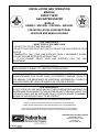 1
1
-
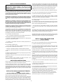 2
2
-
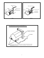 3
3
-
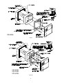 4
4
-
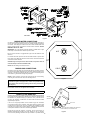 5
5
-
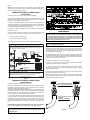 6
6
-
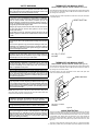 7
7
-
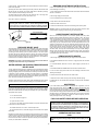 8
8
-
 9
9
-
 10
10
-
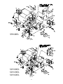 11
11
-
 12
12
-
 13
13
-
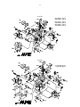 14
14
-
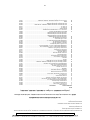 15
15
-
 16
16
-
 17
17
-
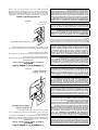 18
18
-
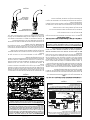 19
19
-
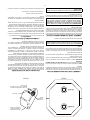 20
20
-
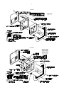 21
21
-
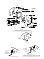 22
22
-
 23
23
-
 24
24


Suburban SW16DEL Mode d'emploi
- Taper
- Mode d'emploi
dans d''autres langues
Autres documents
-
Rheem GHE50SS-76 Mode d'emploi
-
 Dayton 3VE56A Mode d'emploi
-
Atwood G9EXT Manuel utilisateur
-
Dometic MPD 93755 Mode d'emploi
-
GSW Chauffe-eau électriques Space Saver Manuel utilisateur
-
 Girard Products GSWH-1M Le manuel du propriétaire
-
-
A.O. Smith FMD 50 Manuel utilisateur
-
-

