Mitsubishi Electric LD77MS2/LD77MS4/LD77MS16 Le manuel du propriétaire
- Taper
- Le manuel du propriétaire

LD77MS-U-HW
Before Using the Product
Please read this document before use. Keep this for future reference and make sure that end
users will read this.
Related manuals
Before using the product, please read "Safety Guidelines" that is supplied with the CPU module.
Confirm the following descriptions:
●SAFETY PRECAUTIONS
●CONDITIONS OF USE FOR THE PRODUCT
●EMC AND LOW VOLTAGE DIRECTIVES
●WARRANTY
Manuels associés
Avant d'utiliser ce produit, prenez la peine de lire les "Consignes de sécurité" fournies avec le
module CPU.
Revoir les points suivants :
●PRÉCAUTIONS DE SÉCURITÉ
●CONDITIONS D'UTILISATION DU PRODUIT
●DIRECTIVES EMC ET BASSE TENSION
●GARANTIE
Details of the product are also described in the manual shown below (sold separately).
Please read the manual and understand the functions and performance of the product to use it
correctly.
• MELSEC-L LD77MS Simple Motion Module User's Manual (Positioning Control)
IB-0300211 (1XB961)
• MELSEC-Q/L QD77MS/QD77GF/LD77MS/LD77MH Simple Motion Module User's Manual
(Synchronous Control)
IB-0300174 (1XB943)
Packing list
Check that the following items are included in the package.
Operating ambient temperature
Use the product within the range from 0 to 55.
Température ambiante de fonctionnement
Utiliser le produit à une température ambiante entre 0
et 55
.
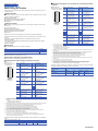
Signal layout for external input connection connector
*1 Input type from manual pulse generator/incremental synchronous encoder is switched in "[Pr.89] Manual pulse
generator/Incremental synchronous encoder input type selection". (Only the value specified against the axis 1
is valid.)
0: Differential-output type (Default value)
1: Voltage-output/open-collector type
*2 Set the signal input form in "[Pr.24] Manual pulse generator/Incremental synchronous encoder input selection".
*3 Voltage-output/open-collector type of manual pulse generator/incremental synchronous encoder:
Connect the A-phase/PLS signal to HA, and the B-phase/SIGN signal to HB.
*4 Differential-output type of manual pulse generator/incremental synchronous encoder:
Connect the A-phase/PLS signal to HAH, and the A-phase/PLS inverse signal to HAL.
Connect the B-phase/SIGN signal to HBH, and the B-phase/SIGN inverse signal to HBL.
*5 Do not connect to any of the terminal explained as "No connect".
*6 Set the external command signal [DI] in "[Pr.95] External command signal selection" at LD77MS16 use.
*7 Do not connect to any of the terminal at LD77MS2.
*8 "COM" is the common terminal of DI1, DI2, DI3 and DI4.
*9 Do not use 1, 2, 14 and 15 for other than the power supply of manual pulse generator.
Note that 2 and 15 are also used for the pulse signal ground of the manual pulse generator/incremental
synchronous encoder A-phase and B-phase.
The table below shows applicable external input wiring connector. When wiring, use applicable
wires.
*1 AWG24 (0.2 mm
2
) is recommended.
Affectation des signaux au connecteur de raccordement d'entrée
externe
*1 Le type d'entrée en provenance du générateur d'impulsions manuel/encodeur synchrone incrémentiel permute
en mode "[Pr.89] Manual pulse generator/Incremental synchronous encoder input type selection". (Seule la
valeur spécifiée pour axe 1 est valide.)
0: Type différentiel-sortie (valeur par défaut)
1: Type tension-sortie/ouvert-collecteur
*2 Adopter une forme d'entrée de signal dans "[Pr.24] Manual pulse generator/Incremental synchronous encoder
input selection".
*3 Type tension-sortie/ouvert-collecteur du générateur d'impulsions manuel/encodeur synchrone incrémentiel:
Raccorder le signal Phase A/PLS sur HA, et le signal Phase B/SIGN sur HB.
*4 Type différentiel-sortie du générateur d'impulsions manuel/encodeur synchrone incrémentiel:
Raccorder le signal Phase A/PLS sur HAH, et le signal Phase A/PLS inversé sur HAL.
Raccorder le signal Phase B/SIGN sur HBH, et le signal Phase B/SIGN inversé sur HBL.
*5 Ne rien raccorder à aucune des bornes portant la mention "Non connecté".
*6 Régler le signal de commande externe [DI] dans "[Pr.95] External command signal selection" pour utiliser un
LD77MS16.
*7 Pour un LD77MS2, ne raccorder aucune des bornes.
*8 La borne "COM" est commune à DI1, DI2, DI3 et DI4.
*9 Ne pas utiliser 1, 2, 14 et 15 dans un but autre que l'alimentation du générateur d'impulsions manuel.
On remarquera que 2 et 15 s'utilisent comme masse du signal impulsionnel de générateur manuel
d'impulsions/phase A et phase B de codeur synchrone à incrémentation.
Le tableau ci-dessous indique quels connecteurs on peut utiliser comme connecteur de câblage
des entrées externes.Pour le câblage, utiliser les fils prescrits.
*1 AWG24 (0,2 mm
2
) est la taille recommandée.
BCN-B62008-321-E(1806)MEE
LD77MS2 LD77MS4 LD77MS16
Item Quantity
Module 1
"Before Using the Product" (this document) 1
Pin
number
Signal name Pin
number
Signal name
1 Manual pulse generator
power supply output (+5VDC)
(5V)
*9
14 Manual pulse generator
power supply output (+5VDC)
(5V)
*9
2 Manual pulse generator
power supply output (GND)
(SG)
*9
15 Manual pulse generator
power supply output (GND)
(SG)
*9
3 Manual pulse
generator/Incremental
synchronous encoder A-
phase/PLS (HA)
*1*2*3
16 Manual pulse
generator/Incremental
synchronous encoder B-
phase/SIGN (HB)
*1*2*3
4 Manual pulse
generator/Incremental
synchronous encoder A-
phase/PLS (HAH)
*1*2*4
17
Manual pulse
generator/Incremental
synchronous encoder B-
phase/SIGN (HBH)
*1*2*4
5 Manual pulse
generator/Incremental
synchronous encoder A-
phase/PLS (HAL)
*1*2*4
18 Manual pulse
generator/Incremental
synchronous encoder B-
phase/SIGN (HBL)
*1*2*4
6 No connect
*5
19 No connect
*5
720
821
922
10 Forced stop input signal (EMI) 23 Forced stop input signal
common (EMI.COM)
11 External command
signal/switching signal (DI1)
*6
24 External command
signal/switching signal (DI2)
*6
12 External command
signal/switching signal
(DI3)
*6*7
25 External command
signal/switching signal
(DI4)
*6*7
13 Common (COM)
*8
26 Common (COM)
*8
External input wiring connector Wire
Model Diameter Typ e Material Temperature rating
LD77MHIOCON AWG30 to AWG24
*1
(0.05 to 0.2 mm
2
)
Stranded Copper 75 or more
141
2613
2512
2411
2310
229
218
207
196
18
5
17
4
163
152
Front view of
the module
External input
connection connector
(module side)
Numéro
de
broche
Nom du signal Numéro
de
broche
Nom du signal
1 Sortie alimentation
générateur d'impulsions
manuel (+5VDC) (5V)
*9
14 Sortie alimentation
générateur d'impulsions
manuel (+5VDC) (5V)
*9
2 Sortie alimentation
générateur d'impulsions
manuel (GND) (SG)
*9
15 Sortie alimentation
générateur d'impulsions
manuel (GND) (SG)
*9
3 Générateur d'impulsions
manuel/Encodeur synchrone
incrémentiel Phase A/PLS
(HA)
*1*2*3
16 Générateur d'impulsions
manuel/Encodeur synchrone
incrémentiel Phase B/SIGN
(HB)
*1*2*3
4 Générateur d'impulsions
manuel/Encodeur synchrone
incrémentiel Phase A/PLS
(HAH)
*1*2*4
17
Générateur d'impulsions
manuel/Encodeur synchrone
incrémentiel Phase B/SIGN
(HBH)
*1*2*4
5 Générateur d'impulsions
manuel/Encodeur synchrone
incrémentiel Phase A/PLS
(HAL)
*1*2*4
18 Générateur d'impulsions
manuel/Encodeur synchrone
incrémentiel Phase B/SIGN
(HBL)
*1*2*4
6 Non connecté
*5
19 Non connecté
*5
720
821
922
10 Signal d'entrée d'arrêt forcé
(EMI)
23 Signal d'entrée d'arrêt forcé
Commun (EMI.COM)
11 Signal de commande
externe/signal de
commutation (DI1)
*6
24 Signal de commande
externe/signal de
commutation (DI2)
*6
12 Signal de commande
externe/signal de
commutation (DI3)
*6*7
25 Signal de commande
externe/signal de
commutation (DI4)
*6*7
13 Commun (COM)
*8
26 Commun (COM)
*8
Connecteur de câblage des
entrées externes
Fil
Modèle Diamètre Type Matériau Classe de
température
LD77MHIOCON AWG30 à AWG24
*1
(0,05 à 0,2 mm
2
)
Torsadé Cuivre 75
ou plus
141
2613
2512
2411
2310
229
218
207
196
18
5
17
4
163
152
Vue de l'avant
du module
Connecteur de
raccordement d'entrée
externe (côté module)
-
 1
1

Mitsubishi Electric LD77MS2/LD77MS4/LD77MS16 Le manuel du propriétaire
- Taper
- Le manuel du propriétaire
dans d''autres langues
Documents connexes
-
Mitsubishi Electric QD77GF Le manuel du propriétaire
-
-
-
-
-
-
-
-
-