Harman Stove Company FireLuxe Direct Vent Gas Stove With Top Cooking Burner System Manuel utilisateur
- Catégorie
- Poêles
- Taper
- Manuel utilisateur
Ce manuel convient également à

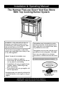
Installation & Operating Manual
The Harman FireLuxe Direct Vent Gas Stove
With Top Cooking Burner System
WARNING: If the information in these in-
structions is not followed exactly, a fire or
explosion may result causing property dam-
age, personal injury or loss of life.
- WHAT TO DO IF YOU SMELL GAS
• Do not try to light any appliance.
• Do not touch any electrical switch; do not
use any phone in your building.
• Immediately call your gas supplier from a
neighbor’s phone. Follow the gas sup-
plier’s instructions.
• If you cannot reach your gas supplier, call
the fire department.
- Installation and service must be performed by
a qualified installer, service agency or the gas
supplier.
INSTALLER: Leave this manual with the appliance.
CONSUMER: Retain this manual for future reference.
This appliance may be installed in an after-
market, permanently located manufactured
home (USA only) or in a mobile home, where
not prohibited by local codes.
This appliance is for use only with the type of
gas indicated on the rating plate. This appli-
ance is not convertible for use with other
gases, unless a certified conversion kit is used.
C
Ce manual est disponsible en Français sur demande.
- Do not store or use gasoline or other flam-
mable vapors and liquids in the vicinity of this
or any other appliance.
Report # 135-S-15-5

2
AVERTISSEMENT: Assurez-vous de bien suivre
les instructions données dans cette notice pour
réduire au minimum le risque d’incindie ou
d’explosion ou pour éviter tout dommage
matériel, toute blessure ou la mort.
- Ne pas entreposer ni utilizer d’essence ni
d’autres vapeurs ou liquides inflammables dans
le voisinage de cet appareil ou de tout autre
appareil.
- QUE FAIRE SI VOUS SENTEZ UNE ODEUR DE
GAZ:
•
Ne pas tenter d’allumer d’appareil.
• Ne touchez à aucan interrupteur. Ne pas
vous servir des téléphones se trouvant
dans le bâtiment où vous trouvez.
• Appelez immédiatement votre
fournisseur de gaz depuis un voisin.
Suivezles instructions du fournisseur.
• Si vous ne pouvez rejoindre le fournisseur
de gaz, appelez le service des incindie.
- L’installation et l’entretien doivent être assurés
par un installateur ou un service d’entretien
qualifié ou par le fournisseur de gaz.
Cet appareil peut être installé dans une maison
préfabriquée (mobile) déjà installée à demeure
si kes règlements locaux le permettent.
Cet appareil doit être uniquement avec las type
de gaz indiqué sur la plaque signalétique. Cet
appareil ne peut être converti à d’autres gaz,
sauf si une trousse de conversion est utilisée.
Ne pas utiliser cet appareils’il a été plongé,
meme partiellement, dans l’eau. Appeler un
technician qualifié pour inspecter l’appareail et
remplacer toute partie du système de commande
et toute commande qui a été plongée dans /’eau.
Attention. Au moment de l’entretien des com-
mandes, étiquetez tous les fils avant de les dé-
brancher. Des erreurs de la câblage peuvent en-
traîner un fonctionnement inadequate et dan-
gereux.
S’assurer que l’appareil fonctionne adéquate-
ment une fois l’entretien terminé.
AVERTISSEMENT. Ne pas utiliser l’appareil
si le panneau frontal en verre n’est pas en place,
est craqué ou brisé. Confiez le remplacement du
panneau à un technician agree.
INSTALLATEUR: Laissez cette notice avec l’appareil.
COMSOMMATEUR: Conservez cette notice pour consultation ultérieur.

3
TABLE OF CONTENTS
IMPORTANT SAFETY INFORMATION 4
SPECIFICATIONS 5
INSTALLATION 6
MASSACHUSETTS REQUIREMENTS 7
VENTING 8
ASSEMBLY 14
LIGHTING AND OPERATION 23
REMOTE CONTROL HANDSET OPERATION & PROGRAMMING 26
MAINTENANCE 28
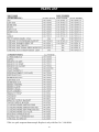
PARTS LIST 30
WARRANTY 31

4
IMPORTANT SAFETY INFORMATION
The installation must conform with local codes or, in the absence of local codes, with the National Fuel
Gas Code, ANSI Z223.1 or the Canadian Installation Code, CAN/CGA B149.
A manufactured home (USA only) or mobile home OEM installation must conform with the Manufactured
Home Construction and Safety Standard, Title 24 CFR, Part 3280 or when such a standard is not applica-
ble, the Standard for Manufactured Home Installations, ANSI/BCSBCS A225.1, or Standard for Gas
Equipped Recreational Vehicles and Mobile Housing, CSA Z240.4.
The appliance and its appliance main gas valve must be disconnected from the gas supply piping system
during any pressure testing of that system at test pressures in excess of 1/2 psi (3.5 kPa).
The appliance must be isolated from the gas supply piping system by closing its equipment shutoff valve
during any pressure testing of the gas supply piping system at test pressures equal to or less than 1/2 psi (3.5
kPa).
The installation must provide for adequate ventilation air to the appliance.
This gas appliance must not be connected to a chimney flue serving a separate solid-fuel burning appliance.
The appliance, when installed, must be electrically grounded in accordance with local codes, or, in the
absence of local codes, with the National Electrical Code ANSI/NFPA 70, or the Canadian Electrical Code,
CSA C22. 1.
When the appliance is installed directly on carpeting or non-ceramic tile or other combustible material other
than wood flooring, the appliance shall be installed on a metal or wood panel extending the full width and
depth of the appliance. A commercially available hearth pad meets this requirement.
The appliance area must be kept clear and free from combustible materials, gasoline and other flammable
vapors and liquids.
The flow of combustion and ventilation air must not be obstructed.
Do not use this appliance if any part has been under water. Immediately call a qualifed service technician
to inspect the appliance and to replace any part of the control system and any gas control which has been
under water.
Due to high temperatures, the appliance should be located out of traffic and away from furniture and
draperies.
Children and adults should be alerted to the hazards of high surface temperatures and should stay away to
avoid burns or clothing ignition.
Young children should be carefully supervised when they are in the same room as the appliance.
Clothing or other flammable material should not be placed on or near the appliance.
Any screen or guard removed for servicing an appliance must be replaced prior to operating the appliance.
Installation and repair should be done by a qualified service person. The appliance should be inspected
before use and at least annually by a professional service person. More frequent cleaning may be required
due to excessive lint from carpeting, bedding material, etc. It is imperative that the control compartments,
burners and circulating air passageways of the appliance be kept clean.
WARNING: Do not operate the appliance with the glass front removed, cracked or broken.
Replacement of the glass should be done by a qualified service person.
WARNING: Use only replacement glass, part number 3-40-21001500 and glass gasket, part number
3-44-00539. Do not use substitute materials. Do not strike or slam the glass front. Do
not use abrasive cleaners. Do not clean when hot.

5
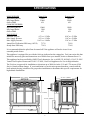
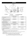
SPECIFICATIONS
MAIN BURNER Natural Gas Propane (LP)
Input Rating-Btu/hr 36000 36000
Min. Input-Btu/hr 23000 23000
Orifice-DMS #34 #50
COOKING BURNER
Input Rating-Btu/hr 12000 12000
Min. Input-Btu/hr 3500 3500
Orifice-DMS #52 #58
GAS SUPPLY
Manifold Pressure 4.5”w.c./1.3kPa 10.0”w.c./2.5kPa
Min. Supply Pressure 5.0”w.c./1.3kPa 11.0”w.c./2.8kPa
Max. Supply Pressure 10.0”w.c./1.8kPa 13.0”w.c./3.3kPa
Annual Fuel Utilization Efficiency (AFUE) 72.7% 74.9%
Steady State Efficiency 73.4% 75.6%
It is recommended that the pilot flame be turned off if the appliance will not be in use for an
extended period of time.
This appliance is equipped for use with the fuel type indicated on the rating plate. Fuel conversion kits that
include the necessary parts and instructions are available from your installer, dealer or Harman Stove Co.
This appliance has been certified by OMNI-Test Laboratories, Inc. to ANSI Z21.88-2005 • CSA 2.33-2005
Vented Gas Fireplace Heaters and CAN1-2.17-M91, Gas-Fired Appliances for Use At High Altitudes.
The FireLuxe is approved for installation at elevations up to 2000 feet in the U.S. and 1370 meters (4500
feet) in Canada without change. If your installation is at an elevation greater than these, consult with the
local authority having jurisdiction for gas product installations to determine their specific requirements for
high altitude installations.
28” (71cm)
23 1/4” (59cm)
30 1/2” (77.5cm)
20 1/2”” (52cm)

6
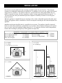
INSTALLATION
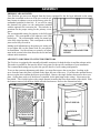
MINIMUM CLEARANCES TO COMBUSTIBLE CONSTRUCTION
Stove to Left Side Wall 6” (150mm) Stove to Corner Wall 6” (150mm)
Stove to Right Side Wall 6” (150mm) Stove to Ceiling 30” (760mm)
Stove to Rear Wall 6” (150mm) Stove to 10” Deep Mantel 30” (760mm)
Max. Alcove Depth 24” (610mm)
Several issues must be addressed when selecting a suitable location for your FireLuxe. The minimum
clearances to combustible construction are listed below. In addition, access to the gas supply and electrical
supply must be considered. The location of the stove will also affect the venting requirements and you
must be certain the location will allow compliance with the venting requirements shown on pages 8 – 13.
You must also insure that your installation provides adequate accessibility clearance for servicing and
proper operation.
When the appliance is installed directly on carpeting or tile or other combustible material other than wood
flooring, the appliance shall be installed on a metal or wood panel extending the full width and depth of the
appliance.
Installation and repair should be done by a qualified service person. The appliance should be inspected
before use and at least annually by a professional service person. More frequent cleaning may be required
due to excessive lint from carpeting, bedding material, etc. It is imperative that the control compartments,
burners and circulating air passageways of the appliance be kept clean.
CEILING MANTEL
CORNER
WALLS
A = 6” (150mm)
B = 6” (150mm)
C = 6” (150mm)
D = 24” (610mm) Max. Alcove Depth
E = 6” (150mm)
F = 30” (760mm)
G = 30” (760mm)
H = 10” (250mm) Max.
A
B
C
E
E
D
F
H
G

7
INSTALLATION
The gas stove is shipped with a flexible connector that has a 1/2” NPT female connection. The gas supply
piping should have a separate gas shutoff valve and a 1/8” NPT plugged tapping upstream of the valve. The
stove and its main control valve must be disconnected from the gas supply piping system during any pres-
sure testing of that system at test pressures in excess of 1/2 psi (3.5 kPa). The stove must be isolated from
the gas supply piping system by closing the main control valve during any pressure testing of the gas supply
system at test pressures equal to or less than 1/2 psi (3.5 kPa). After the gas supply has been connected,
apply a soapy water solution to all the fittings to check for gas leaks. Never use a flame to test for leaks.
REQUIREMENTS FOR THE COMMONWEALTH OF MASSACHUSETTS
This product must be installed by a licensed plumber or gas fitter when installed within the Com-
monwealth of Massachusetts. If this appliance is installed in a dwelling, building or structure used in
whole or in part for residential purposes and the installation includes a horizontal vent termination
that is less than seven (7) feet above the finished grade in the area of the venting, including but not
limited to decks and porches, a hard-wired carbon monoxide detector with an alarm and battery
back-up must be installed on the floor level of the dwelling, building or structure where the appli-
ance is to be installed.
Additionally, a hard-wired or battery operated carbon monoxide detector with an alarm must be in-
stalled on each additional level of the dwelling, building or structure served by the appliance. It shall
be the responsibility of the property owner to secure the services of qualified licensed professionals
for the installation of hard-wired carbon monoxide detectors.
In the event that the horizontally vented appliance is installed in a crawl space or attic, the hard-
wired carbon monoxide detector with alarm and battery back-up may be installed on the next adja-
cent floor level.
In the event that this requirement cannot be met at the time of completion of the installation of the
appliance, the owner shall have a period of thirty (30) days to comply with the requirement. How-
ever, during said thirty (30) day period, a battery operated carbon monoxide detector with alarm
must be installed.
Each carbon monoxide detector as required in accordance with the above provisions must comply
with NFPA 720 and be ANSI/UL 2034 and IAS certified.
In addition when the stove is horizontally vented and the vent termination is less than seven (7) feet
above finished grade a metal or plastic identification plate must be permanently mounted to the exte-
rior of the building at a minimum height of eight (8) feet above grade directly in line with the ex-
haust vent terminal. The sign shall read, in print size no less than one-half (1/2) inch in size, “GAS
VENT DIRECTLY BELOW. KEEP CLEAR OF ALL OBSTRUCTIONS”.
A COPY OF THESE INSTRUCTIONS PLUS ALL VENTING INSTRUCTIONS WHICH IN-
CLUDE PARTS LISTS, AND/OR ALL VENTING DESIGN INSTRUCTIONS MUST REMAIN
WITH THE STOVE AT THE COMPLETION OF THE INSTALLATION.
ATTENTION INSTALLERS: Mark below which venting system was used in the installation. These
instructions must remain with the FireLuxe Installation & Operation Manual.
Simpson DuraVent GS
AmeriVent Direct Security Secure Vent Selkirk DT
To avoid confusion discard the all vent manufacturers instructions that do not apply to this installation.
NOTE: If you will be installing the optional warming shelves, make sure to plan for the additional width
that they occupy. For the details, see the information included with the warming shelf kit.

8
VENTING
The FireLuxe Gas Stove has been tested and listed for installation with 4” X 6 5/8” Simpson DuraVent GS,
AmeriVent Direct, Security Secure Vent and Selkirk DT direct venting components. For specific installa-
tion requirements, follow the installation instructions included by the venting manufacturer with the venting
system components you have chosen. The total vent length may not exceed 40 feet, including vertical rise
and horizontal run. The vent lengths are measured from the stove, not the floor. The minimum vertical rise
required is 2 feet. The maximum allowed horizontal vent run is 20 feet when the venting includes at least 5
feet of vertical rise. The maximum allowed horizontal vent run for vertical rises of less than 5 feet is shown
in the venting charts. No more than three elbows may be used in any installation. The venting charts in-
clude the use of one elbow. For the second or third elbows that are included in the installation, add 4 feet to
the actual horizontal run for each elbow to determine the equivalent horizontal run for the installation.
The venting charts allow a simple way to determine the recommended initial settings for both the air inlet
and exhaust restrictors. These settings have been determined by extensive testing and will be a good start-
ing point while setting up the stove. Small adjustments from these settings may be needed to account for
specific installation variables. Please see the instructions on pages 21 - 22 for how to adjust the restrictors.
The letters (A-E) designate the position of the air inlet restrictor. When ½ is added to the letter designation,
this indicates that the position is halfway between adjacent letters. The numbers (0-8) indicate the position
of the exhaust restrictor. When ⅛, ¼, ⅜, ½, or ¾ is added to the number designation, this indicates that the
position is fractionally between adjacent numbers. For example, 5¼ is one-fourth the way between 5 and 6.
To use the charts, determine the horizontal run length and vertical rise length (in feet) for your installation.
If more than one elbow is used, add 4 feet to the actual horizontal run length for each additional elbow to
get the equivalent horizontal run for the chart. Note: Remember that a maximum of three elbows is al-
lowed. Select the venting chart for the fuel type (Natural Gas or Propane (LP) Gas) and find the box on the
chart that corresponds to the vertical rise and actual horizontal run (or equivalent horizontal run, if two or
three elbows are used) and read the settings for the inlet air restrictor (A-E) and exhaust restrictor (0-8).
Examples are shown below and on page 9.
The FireLuxe is shipped with a Simpson DuraVent GS starter section that is specifically designed for the
FireLuxe. Regardless of the venting brand you chose, you must use the provided DuraVent starter section.
All of the venting brands listed for use with the FireLuxe are compatible with the provided starter section.
For venting system installation details, refer to the instructions provided with the venting system you have
chosen. Each brand has specific installation requirements that must be followed to insure a safe and func-
tional venting system for your FireLuxe.
Note: The Fireluxe is shipped from the factory with restrictor settings for 2 feet of vertical rise and 1 foot
of horizontal run and for the fuel type listed on the rating plate attached to the rear of the stove.
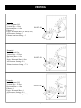
E½
6¾
Example 1
Fuel = Propane (LP)
Vertical Rise = 15 feet
Horizontal Run = 8 feet
Elbows = 1
Equivalent Horizontal Run = 8 feet
Air Restrictor Setting = E½
Exhaust Restrictor Setting = 6¾
INLET AIR
EXHAUST

9
VENTING
Example 2
Fuel = Propane (LP)
Vertical Rise = 6 feet
Horizontal Run = 8 feet
Elbows = 3
Equiv. Horizontal Run = 16 feet (8+4+4)
Air Restrictor Setting = C
Exhaust Restrictor Setting = 3
C
3
EXHAUST
INLET AIR
E½
7⅜
Example 3
Fuel = Natural Gas
Vertical Rise = 22 feet
Horizontal Run = 0 feet
Elbows = 0
Equiv. Horizontal Run = 0 feet
Air Restrictor Setting = E ½
Exhaust Restrictor Setting = 7 ⅜
EXHAUST
INLET AIR
E½
6½
Example 4
Fuel = Propane (LP)
Vertical Rise = 12 feet
Horizontal Run = 4 feet
Elbows = 1
Equiv. Horizontal Run = 4
Air Restrictor Setting = E ½
Exhaust Restrictor Setting = 6 ½
EXHAUST
INLET AIR

10
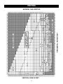
VENTING
VERTICAL RISE IN FEET
HORIZONTAL RUN IN FEET
NATURAL GAS VENTING
IF YOUR VENTING CONFIGURA-
TION FALLS ABOVE THIS DOT-
TED LINE, SEE PAGE 12

11
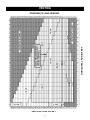
VENTING
VERTICAL RISE IN FEET
HORIZONTAL RUN IN FEET
PROPANE (LP) GAS VENTING
IF YOUR VENTING CONFIGURA-
TION FALLS ABOVE THIS DOT-
TED LINE, SEE PAGE 12

12
VENTING
PLEASE NOTE: If your specific venting configuration falls in a box in the venting charts (on pages 10 &
11) that is above the dotted line ( ), you must use one of the approved direct vent venting systems
that utilizes a stainless steel
inner liner. The dotted line corresponds to a total vent length of 30 feet includ-
ing vertical rise and horizontal run. This requirement is part of the ANSI standards and is based on testing
conducted to determine where the exhaust gas temperature drops to the point where condensation might oc-
cur in the vent pipe. The standards require the use of corrosion resistant liner materials if that specific total
vent length is exceeded.
VENTING INTO AN EXISTING MASONRY OR CLASS A CHIMNEY
The FireLuxe has been tested and found to be in compliance when using an existing chimney as the air con-
duit for the direct venting system. This type of installation is used when replacing an existing wood-
burning stove with a FireLuxe direct vent gas stove. Check with the venting manufacturer to see if they
have the needed components or kits for this type of installation. Also, check the vent manufacturer’s instal-
lation instructions for the specific details and requirements for this type of installation. The chimney must
be in good condition with no cracks or leaks for this type of installation and the venting components must
be sealed where they meet the existing chimney. Also, check with the local authority having jurisdiction to
see if this type of installation is allowed in your area.
RESERVED FOR FUTURE VENTING CONFIGURATION INFORMATION

13
VENT TERMINAL CLEARANCES
VENTING
Venting terminals shall not be recessed into a wall or siding.

14
ASSEMBLY
UNPACKING AND PLACING THE FIRELUXE
By now, you will have removed the shipping carton from the base pallet. The FireLuxe is shipped on spe-
cially designed shipping supports that keep the weight of the stove off the legs to avoid damaging them dur-
ing transit. Cut the strapping that secures the stove to the pallet. The stove must be lifted straight up to dis-
engage it from the shipping brackets. The best place to lift is at the base of the stove sides. The stove top
and front have to be removed in order to unpack and install the logs and top cooking burner parts. Remov-
ing them now will reduce the weight and make it easier to lift the stove. Also, locate the ashlip and ashlip
mounting hardware and set aside in a safe location. It will be installed later.
First, remove the cast iron stove top. This is accomplished by simply lifting up on the top as it is a gravity
fit. The top is heavy and extra care should be taken when handling it, especially if the stove is enameled.
Set the top aside on a padded surface. A carpeted floor is a good choice.
Remove the top cooking grill and the cooking burner cover plate and set aside for now. They are packed in
bubble wrap or foam packing and are located on the now exposed top of the stove’s firebox.
Remove the stove front by lifting it straight up to disengage the tabs that secure it to the sides. Once it is
disengaged, you can move the front away from the stove body. Note: The front doors may have a tendency
to swing open while you are handling the front. Placing a small piece of masking tape around the two doors
where they meet at the center will keep the doors from moving. Set the front aside with the back side down
taking extra care if it is enameled.
With these parts removed and set aside, lift the stove up and off the pallet and set it near to its installation
position. Like any cast iron stove, it is best to pick the stove up while adjusting its position rather than
dragging it on its legs. This reduces the chances of damaging a leg or chipping enamel or of damaging the
hearth surface. This is the best time to install the optional blower kit if being used. See the instructions in-
cluded with the blower kit.
The legs have leveling screws that will allow you to compensate for irregularities on the surface under the
stove. Using as little adjustment as possible for each leveling screw, adjust them as needed to get the stove
as level as possible both side to side and front to back. This is important since the FireLuxe includes a top
cooking burner and having the stove level will reduce the likelihood of spillage while cooking.
The FireLuxe is shipped set up for the fuel type indicated on the rating plate attached to the rear of the
stove. Note: If you need to switch fuels, please see the instructions included with the appropriate fuel con-
version kit. The logs are shipped in protective material inside the firebox and do need to be unpacked and
installed on the burner.
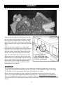
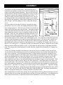
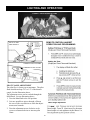
With the stove top and front removed and safely set aside
during the unpacking process, unlatch each of the three
glass frame latches by pulling forward on the latch finger
tabs while lifting up. See the adjacent illustration. This
will allow the glass frame to tip slightly forward. The glass
is loose in the frame, held in place only by friction from
the gasket so it is very important to support both the glass
and the frame when handling. Place your thumbs on the
outside of the glass frame and wrap your fingers around
the frame and onto the glass. Squeeze the frame and glass
while moving. Carefully lift the glass frame and glass up
and off the stove. Set the glass and frame aside on a pad-
ded surface. The outside of the frame should be facing
down so the glass will stay in place.
UNLATCHING DETAIL-
PULL FORWARD AND
UP TO UNHOOK LATCH
FROM GLASS FRAME

15
ASSEMBLY
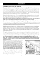
LEFT REAR LOG
RIGHT REAR LOG
LEFT REAR LOG RECESS
RIGHT REAR LOG RECESSES
LEFT FRONT LOG RECESS
RIGHT FRONT LOG RECESS
PINS
LOGS AND EMBERS
Slide the logs and packing out of the firebox and set on the floor. Carefully unpack each of the four logs
and three loose ember pieces. The logs and embers are somewhat fragile and will not survive being
dropped from any significant height.
Remove the protective cover material from the top of the burner.
Each of the four logs is unique and must be placed in a precise location on top of the burner. The burner
and log system is designed to facilitate correct placement of the logs. Flat recessed areas on the burner top
are keyed to each of the four main logs. The rear logs also have locating pins with corresponding sockets in
the logs. The following illustration highlights these features.
Place the left rear log first. There is recessed area in the burner top as well as a locating pin in and a cor-
responding socket in the log. Line-up the socket over the pin and place the log in the recess.
Place the right rear log next. There is a recessed area on the top of the burner that corresponds to the shape
of the base of the log. Simply place the log in the recess. The following illustration shows the proper posi-
tions for the two rear logs.

16
ASSEMBLY
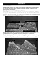
Place the left front log next. Again, there is a recess on the burner top that corresponds to the shape of the
flat base of the log. Place the left end of the log in the recess and rest the right end on the left rear log using
the illustration below as a guide. Place the right front log last. Again, place the flat base of the log in the
corresponding recess in the burner top per the illustration below.
LEFT FRONT LOG
RIGHT FRONT LOG
There are three loose ember pieces. Each ember piece has a specific location on the burner. Refer to the
illustration below to get the proper placement and orientation for each ember piece. If you look carefully,
you will see that each ember has features that will help you in placement relative to the burner surface and
the logs.
EMBER 1
EMBER 2
EMBER 3

17
ASSEMBLY
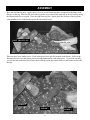
When correctly placed, the logs and embers will look like the illustration below.
LATCHING DETAIL-
PULL FORWARD AND
DOWN TO HOOK LATCH
OVER GLASS FRAME
After the logs and embers have been placed, the next
step is to replace the glass panel and frame. Carefully
pick up the glass and glass frame assembly by grasp-
ing the sides of the frame and using your thumbs and
fingers to hold the glass in place within the gasket and
frame.
With the glass frame (and glass) at a slight angle
(leaving room for your fingers between the frame and
the firebox) insert the bottom edge of the frame into
the frame retainer located on the bottom front of the
firebox. Take care to center the frame from left to
right. Once the bottom edge is in place, move your
fingers out of the way and press the top of the frame
against the firebox while pushing down to be sure the
frame is fully engaged in the frame retainer. Hold the
frame in place with one hand and engage the three
glass frame latches by pulling out and down while
hooking them over the frame.
Top or Rear Vent
The FireLuxe has provisions for either top or rear venting but is shipped from the factory set-up for top
venting. The rear position is sealed with a special cover plate. If your installation requires rear-venting,
you will need to reverse the positions of the starter section and the cover plate.
Remove the four screws that secure the vent starter section flange to the stove and remove the starter.
There are two ceramic fiber gaskets that seal the starter to the stove. These gaskets are very important!
Take care in handling these gaskets as they are somewhat fragile and will tear. Remove the vent cover plate
from the rear of the stove following the same procedure as the starter. Install the cover plate on the top vent
opening.

18
ASSEMBLY
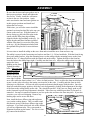
It is now time to install the ashlip on the stove front and to install the stove front and stove top.
The ashlip is secured to the front using two brackets and four 1/4 – 20 hex head bolts. With the front facing
down on a padded surface, align the mounting bosses on the ashlip with the mounting bosses on the front.
Install the two “L”-shaped brackets with the slotted end on the ashlip. Tighten the bolts to the front but
leave the bolts to the ashlip finger tight. Carefully turn the front over. Adjust the ashlip so that it is tight
against the lower
molding on the front.
Tighten the ashlip
bolts. Take care with
an enamel stove to
prevent chipping.
Replace the stove
front by aligning the
outer edges with the
stove sides while the front is about ½ to 1” above its final position. This is to allow the sheet metal tabs that
secure it to the sides to be above the mating cast iron tabs on the sides. Carefully push the front in while
allowing it to slide down. All four tabs (two top and two bottom) should engage with the sides. Once the
front has reached the proper position, check the vertical alignment by looking at the alignment of the edges
of the front to the casting details on the side. They should be parallel. If they are not, simply push or pull
on the front until a good visual alignment is obtained. Take extra care with this procedure if your stove is
enameled. Just move in small increments as you line up the tabs and lower the front into place. If you take
your time, you will avoid chipping. Remove any
masking tape used to secure the doors.
Be sure that the inner and outer gaskets are in
their proper positions. Install and tighten the
four screws. Finally, install the vent starter
section in the rear vent position. Again,
make sure that the inner and outer gaskets are
in their proper positions and install and
tighten the four screws.
INNER
GASKETS
OUTER
GASKETS
STARTER SECTION
COVER
PLATE
Next, install the brass diffuser ring and top burner
cover on the cooking burner. This is a small round
disk that sits on top of the brass diffuser ring on the
top burner. If you look at the back side of the diffuser,
you will see alignment tabs. They correspond to
alignment locations on the burner. The cover is sim-
ply centered in the diffuser.
BRASS DIFFUSER RING
BURNER COVER
At this time, you will also want to install the
optional cast iron plate that fills in the top vent
cutout on the stove top. With the bottom of
the top facing up, place the filler plate in the
cutout with the filler plate edge molding
aligned with the edge molding on the top. Us-
ing the bracket and three fasteners included
with the filler plate kit, secure the filler plate
to the top. See the illustration included with
the optional filler plate kit for more informa-
tion.
ASHLIP
SLOT
BRACKET
FRONT

19
ASSEMBLY
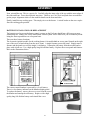
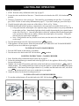
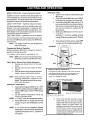
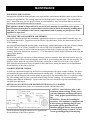
The remote control handset is powered by a 9-volt battery.
There is a low battery indicator on the handset display panel.
To replace the battery, remove the access cover from the rear of
the handset and unsnap the old battery. Replace with a high
quality long-life alkaline battery and reinstall the cover.
BATTERY INSTALLATION OR REPLACEMENT
The batteries used to power the burner control systems on the FireLuxe should last a full season or more
with normal use. Battery life for the main burner control system will be reduced if you are manually modu-
lating the flame up and down on a frequent basis.
There are three battery locations.
The electronic ignition module for the cooking burner is located behind an access panel located on the right
rear of the stove (when looking from the stove front). A single fastener secures the panel. Simply remove
fastener and the panel to access the single 9-volt battery. Unsnap the old battery from the module and re-
place with a fresh one. Use a high quality long-life alkaline battery. Replace the access panel and fastener.
Refer to the illustrations below.
ACCESS COVER
FASTENER
9V BATTERY
Next, reinstall the top. This is a gravity fit. Carefully align the inner edge of the top with the outer edges of
the sides and front. Lower the top down into place. Check to see if it is level and push down as needed to
get the proper alignment relative to the aesthetic details on the front and sides.
Finally, install the top cooking grate. This simply sits over the burner. A raised border on the stove top de-
fines the cooking grate position.

20
ASSEMBLY
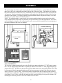
The main heating valve battery pack is located at the center rear of the stove. A removable valve access
panel covers the valve components and simply lifts up and off the stove back. The batteries are located in
the control module next to the actual valve. The battery access cover lifts and slides off to expose the four
AA batteries. Note the orientation of each battery as you replace the old with new as this is critical to the
operation of the control. Use only high quality long-life alkaline batteries. Replace the battery cover and
the valve access panel. Refer to illustrations below.
NOTE: The control module is secured to the valve bracket with hook-and-eye strips and can be pulled
away from the bracket if necessary to gain better access to the battery cover and compartment. Be certain
not to dislodge the wiring from the control module and be sure to place the module back it its original posi-
tion after the batteries and cover are installed.
CONTROL MODULE
COVER
AA BATTERIES
VALVE ACCESS
PANEL
CONTROL MODULE
VALVE
GAS CONNECTION
The FireLuxe is shipped from the factory with a flexible gas connector that has a 1/2” NPT female connec-
tion. The gas supply piping should have a separate gas shut-off valve and a 1/8” NPT plugged tapping up-
stream of the valve. The FireLuxe and its inlet regulator. Main burner valve and cooking burner valve must
be disconnected from the gas supply piping system during any pressure testing of that system at test pres-
sures in excess of 1/2 psi (3.5kPa). The FireLuxe must be isolated from the gas supply piping system by
closing the main control valve during any pressure testing of the gas supply system at test pressures equal to
or less than 1/2 psi (3.5kPa). After the gas supply has been connected, apply a soapy water solution to all
the fittings to check for gas leaks. Never use a flame to test for leaks.
La page est en cours de chargement...
La page est en cours de chargement...
La page est en cours de chargement...
La page est en cours de chargement...
La page est en cours de chargement...
La page est en cours de chargement...
La page est en cours de chargement...
La page est en cours de chargement...
La page est en cours de chargement...
La page est en cours de chargement...
La page est en cours de chargement...
La page est en cours de chargement...
-
 1
1
-
 2
2
-
 3
3
-
 4
4
-
 5
5
-
 6
6
-
 7
7
-
 8
8
-
 9
9
-
 10
10
-
 11
11
-
 12
12
-
 13
13
-
 14
14
-
 15
15
-
 16
16
-
 17
17
-
 18
18
-
 19
19
-
 20
20
-
 21
21
-
 22
22
-
 23
23
-
 24
24
-
 25
25
-
 26
26
-
 27
27
-
 28
28
-
 29
29
-
 30
30
-
 31
31
-
 32
32


Harman Stove Company FireLuxe Direct Vent Gas Stove With Top Cooking Burner System Manuel utilisateur
- Catégorie
- Poêles
- Taper
- Manuel utilisateur
- Ce manuel convient également à
dans d''autres langues
Documents connexes
Autres documents
-
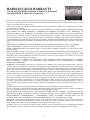
HearthStone Bristol DX 8762 Le manuel du propriétaire
-
RAIS Viva 160 LG Classic Gas Installation & Operation Manual
-
 Lennox Hearth Gas Stove Manuel utilisateur
-
Jøtul GF 200 DV II Lillehammer Manuel utilisateur
-
-
Superior Fireplaces DRT63ST Mode d'emploi
-
-
