Twin Eagles Gas Infrared Heater Le manuel du propriétaire
- Catégorie
- Barbecues
- Taper
- Le manuel du propriétaire
Ce manuel convient également à

P/N: 24254F 07/19
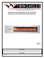
OUTDOOR GAS INFRARED PATIO HEATER
INSTALLATION USE AND CARE MANUAL
MODEL:
TEGH48-B
WARNING:
Improper installation, adjustment, alteration, service, or maintenance can cause property damage, injury or
death. Read the installation, operating and maintenance instructions thoroughly before installing or servicing
this equipment.

A special message…
Congratulations on your purchase of Twin Eagles outdoor gas infrared heater. We have
designed this heater to provide you and your family with many years of great comfort heating
experience. In addition to its Style, Performance and High Quality, this heater is built with pride
in the U.S.A.
This manual gives you easy to follow instructions for installing, operating and maintaining
your TWIN EAGLES heater. We recommend reading this manual carefully before your first use
to insure safety, proper care and operation.
Thank you and welcome!
TWIN EAGLES
_____________________________________________________________________________
FOR YOUR RECORDS
Please record the following information and refer to them when contacting the company or
an authorized service agent. The model number and serial number are found on the nameplate,
located on the upper left corner of the back cover.
Model #: ________________________________
Serial #: _________________________________
Date of Purchase: __________________________
Place of Purchase: __________________________
Type of Gas: NG LP
To the Installer:
Please read these instructions completely before installation and give this manual to the owner.
To the Owner:
Keep this manual in a safe place for future reference.

IMPORTANT SAFETY INFORMATION
WARNING! Read this manual carefully and completely before using your appliance to ensure proper
operation, proper installation, proper servicing and to reduce the risk of fire, burn hazard and/ or other injury.
AVERTISSEMENT! Lire ce manuel avec soin et en entier avant l’utilisation de votre barbecue afin d’en
assurer un fonctionnement, une installation et un entretien adéquats et réduire le risque d’incendie, de brûlures
et d’autres blessures.
WARNING
1. Do not store or use gasoline or other
flammable vapors and liquids in the vicinity
of this or any other appliance.
2. An LP cylinder not connected for use shall
not be stored in the vicinity of this or any
other appliance.
AVERTISSEMENT
1. Ne pas entreposer ni utiliser de l’essence ni
d’autres vapeurs ou liquides inflammables
dans le voisinage de l’appareil, ni de tout autre
appareil.
2. Une bouteille de propane qui n’est pas
raccordée en vue de son utilisation, ne doit pas
être entreposée dans le voisinage de cet appareil
ou de tout autre appareil.
THIS APPLIANCE IS FOR OUTDOOR USE
ONLY:
If stored indoors, detach and leave L.P. cylinder
outdoors.
CE APPARIEL EST POUR UTILISATION À
L’EXTÉRIEUR SEULEMENT:
Si l’appareil est entreposé à l’interieur, enlever
les bouteilles et les laisser à l’extérieur.
BEFORE LIGHTING
1. Read instructions before lighting.
2. Remove the lid during lighting.
3. If ignition does not occur in 5 seconds, turn
the burner control(s) off, wait 5 minutes, and
repeat the lighting procedure.
AVANT D’ALLUMER
L’APPAREIL
1. Lisez les instructions avant d’allumer l’appareil.
2. Retirer le couvercle avant d’allumer l’appareil.
3. Si l’appareil ne s’allume pas en 5 secondes,
fermez le robinet du brûleur, attendez 5 minutes,
et procédez de nouveau à l’allumage.
WARNING: CALIFORNIA PROPOSITION 65
This product can expose you to chemicals including carbon monoxide which is known to the State of
California to cause cancer and reproductive harm. To minimize exposure to the by-products of the burning
fuel or from combustion, always operate this unit according to the use and care manual and provide good
ventilation. California law requires businesses to warn customers of potential exposure to such
substances. For more information go to www.P65Warnings.ca.gov.
AVERTISSEMENT: PROPOSITION 65 DE L'ETAT DE LA CALIFORNIE
Cet appareil peut vous exposer aux produits chimiques et au gaz monoxyde de carbonne reconnue dans
l'Etat de la Californie pour causer le cancer et des problemes de fertilite. Pour minimiser l'exposition de ces-
sous produits combustibles ou de la combustion, utiliser toujours cet appareil en conformitee au manuel
d'utilisation et d'entretien en s'assurant egalement d'une bonne ventilation. La loi de la Californie exige aux
fabricants d'informer leurs clients aux risques d'exposition potentielle a de telles substances. Pour plus
d'information, visiter le site www.P65Warnings.ca.gov

TABLE OF CONTENTS
GAS INFRARED HEATER FEATURES / GETTING STARTED……………………………………………...
GAS INSTALLATION REQUIREMENTS……………………………………………………………………….
LEAK TEST…………….……………………………………………………………………………...............
SELECTING MOUNTING LOCATION…………………………………………………………………………..
MOUNTING CLEARANCES……………………………………………………………………………..............
ELECTRICAL INSTRUCTIONS………………………………………………………………………………….
OPERATING INSTRUCTIONS…………………………………………………………………………………...
PREVENTIVE MAINTENANCE………………………………………………………………………………….
TROUBLESHOOTING GUIDE…………………………………………………………………………………...
EXPLODED VIEW………………………………………………………………………………………………..
REPLACEMENT PARTS LIST…………………………………………………………………………………...
LIMITED PRODUCT WARRANTY……………………………………………………………………………...
WARRANTY REGISTRATION CARD
1
2
3
4
7
9
10
12
13
15
16
17

1
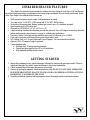
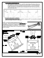
INFRARED HEATER FEATURES
Twin Eagles Gas Infrared Heater extends the outdoor activities during the cool days of fall and through
the winter seasons providing a comfortable warm and inviting environment for your family and friends. Some
of the Twin Eagles Gas Infrared Heater features are:
• Wall mounted wireless remote control (lithium batteries included)
• Two heat levels; 25,000 BTU LOW setting and 37,000 BTU HIGH setting.
• No electrical wiring required. Battery operated gas control valve (AA batteries included).
• Spark ignition with 100% safety plot.
• Slim profile (TEGH48; W = 9” x L = 48” x D = 8”)
• Angle mounting Stainless Steel brackets provides the option of Zero or 30 degree mounting to direct the
radiant heat towards a desired area in a variety of outdoor patio applications.
• Decorative Safety Grille that provides shielding from wind. Wind proof up to 15 MPH.
• Great option for patios with limited floor space of high traffic areas.
• NG (Natural Gas) or LP (Liquid Petroleum Gas or Propane). Gas conversion kits available.
• Optional 120V AC adapter (usage is optional)
• Comes standard with:
o Stainless Steel 16 gauge mounting brackets.
o Flexible gas hose approved for NG or LP installation
o Wall mounted wireless remote control.
GETTING STARTED
1. Inspect the packaging for any physical damage, followed by checking the gas heater inside. If there is
significant damage to the heater, report the damage to the carrier immediately.
2. Check to ensure that all the heater accessories are included.
3. Remove all packaging materials, labels and protective film. DO NOT LEAVE UNIT UNDER THE
SUN WITH PROTECTIVE PLASTIC FILM ON FOR LONG PERIOD OF TIME AS IT WILL
BE DIFFICULT TO REMOVE THE FILM.
4. Read the installation, operation and maintenance manual thoroughly before installing this heater.

2
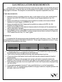
GAS INSTALLATION REQUIREMENTS
Each patio heater is set and tested at the factory for the type of gas supply to be used. Identify the type of
gas, either natural gas or LP gas and make sure that the marking on the nameplate (rating plate) matches the gas
being supplied to the heater. The nameplate is located behind the component compartment access door.
CODE REQUIREMENTS
• Installation must be in accordance with local codes, or in the absence of local codes, with the National
Fuel Gas Code, ANSI Z223.1/NFPA 54, or the Natural Gas and Propane Installation Code, CSA
B149.1.
• Heaters to be installed in Aircraft hangars must be installed in accordance with American National
Standards for Aircraft Hangars, ANSI/NFPA No. 409.
• Heaters to be installed in Public Garages must be installed in accordance with NFPA No. 88A,
Standards for Parking Structures.
• Heaters must be installed so that minimum clearances marked on the heaters will be maintained from
vehicles parked below the heater.
• When equipped with an AC/DC adapter, the heater must be electrically grounded in accordance with the
National Electrical Code, ANSI/NFPA 70, when an external electrical source is utilized. In Canada, the
CSA Canadian Electrical Code, C22.1 Part 1 applies.
GAS SUPPLY
It is important that the inlet gas piping system be adequately sized for the heater(s) it serves. The gas inlet
and manifold pressure required for the heater is listed below. For gas supply line pressures in excess of ½ psig,
consult with your representative or the factory.
Gas Inlet Pressure
Nat Gas
Propane
Maximum Pressure
10” W.C.
13” W.C.
Minimum Pressure
6” W.C.
11” W.C.
Manifold Pressure
5” W.C.
10” W.C
• A minimum pipe size of ½” is required for inlet piping. A ½” leaver handled shut-off gas valve should
be installed within 6 feet of the appliance for servicing the unit.
• Check with local and state plumbing and heating codes regarding sizing of gas lines.
• All gas connections to the heater(s) must be sealed with a gas pipe compound resistant to liquefied
petroleum gasses.
• Installation of a drip leg in the gas supply line is going to each heater is required to minimize the
possibility of any loose scale or dirt within the gas supply line from entering the heater’s control system.
• When checking for gas leaks, do not use an open flame. Use the Leak Test procedures using liquid soap
and water solution.
• For gas supply line pressure in excess of ½ psig, consult the factory or your local representative.
• Installation of 1/8” NPT plugged tapping accessible for test gage connections is required upstream of the
gas supply connections to the heater.

3
IMPORTANT
All gas connections should be made by a qualified technician in accordance with all requirements of the
authority having jurisdiction. The technician must be knowledgeable, specifically trained and experienced in
the installation of this type of gas equipment and related gas system components and with all precautions
required regarding this type of equipment. Some states or provinces require installation and service personnel to
be licensed. If your state or province is such, be sure your contractor bears the appropriate license. If a person
does not meet all requirements and is not qualified for this installation he/she shall not attempt to repair, replace,
install nor do any other type of work or service to this equipment.
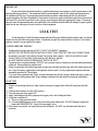
LEAK TEST
At the beginning of each fall/winter season and after filling and reattaching the propane tank, you should
test the unit for gas leaks using soap solution. Periodically inspect the connections for corrosion. If you find a
problem, contact your gas supplier for repairs.
CAUTION BEFORE TESTING
• Finding and/or fixing a gas leak is NOT a “DO-IT-YOURSELF” procedure.
• NEVER USE THE PATIO HEATER WITHOUT FIRST LEAK TESTING THE GAS CONNECTIONS.
• WARNING: DO NOT USE OPEN FLAME TO CHECK FOR LEAKS. USE OF AN OPEN FLAME
COULD RESULT IN A FIRE, EXPLOSION AND BODILY HARM.
• DO NOT SMOKE WHILE PERFORMING THE LEAK TEST!
• To prevent fire or explosion hazard, DO NOT use or permit sources of ignition in the area while performing
a leak test. Perform leak test outdoors only.
• Check to ensure that the flexible hose does not have any cuts and wear that may affect the safety before each
use. Only the factory supplied hose and regulator must be used. Use only replacement regulator and hose
assemblies specified by Twin Eagles.
• If you are using a propane tank, check to ensure that there are no holes, dents, rusted weak spots, cracks, or
other damage on the propane tank. If any damage is detected, the tank should be replaced immediately.
LEAK TEST
1) Prepare a leak testing solution of sudsy water by mixing in a spray bottle with half liquid soap and half
water.
2) Confirm that the heater is in the OFF position.
3) Turn the main gas valve supply ON.
4) Apply leak testing solution by spraying on the pipe joints, valve fittings and hose.
5) A gas leak is detected if;
a) There is a faint gas smell and/or…
b) Growing bubbles appear on any of the connection points and/or hose. DO NOT attempt to ignite the
heater and IMMEDIATELY turn off the gas supply valve.
6) When there is a gas leak, call a qualified service technician. DO NOT use the heater until the leak is
corrected.

4
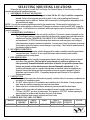
SELECTING MOUNTING LOCATIONS
When selecting a location to install the Twin Eagles Gas Infrared Heater, all the following conditions
must be met before the installation process:
1. ANCHORING TO WALL OR CEILING
a. If the heater is not anchored to support at least 100 lbs. (45 ½ kg) it could be a suspension
hazard. Failure of the supports can result in death. Local codes regarding head clearance
requirements must be observed. Heaters shall be mounted in a fixed position independent of the
gas and electrical supply.
NOTE: Use only the mounting brackets provided by the manufacturer. Heater must be leveled only on a
Horizontal Axis but can be angled to a maximum of 30 degrees in reference to the floor. DO NOT mount the
heater on a vertical axis. Such installation is considered unsafe and improper and will automatically VOID the
product’s warranty.
2. COMBUSTIBLE MATERIALS
a. Combustible means material that can quickly catch fire if it comes in contact with sparks or fire.
The Twin Eagles heater is a remote controlled unit that strictly requires that each heater must be
installed such that the “MINIMUM CLEARANCE TO COMBUSTIBLES” are always met
and maintained. CAUTION should be taken when heaters are used near glass, vinyl siding or
other temperature sensitive construction materials. In some cases it may be necessary to increase
the clearance around the heater to avoid damage to vinyl siding. Check with the manufacturer of
the material siding for details
3. WEATHER CONDITIONS
a. This heater has been designed, tested and approved for outdoor installation and has passed basic
wind and rain tests. However, do not expose the heater under extremely harsh weather
conditions and very windy areas.
4. FIRE SPRINKLERS
a. Fire Sprinklers must be located at an appropriate distance from each heater to avoid accidental
activation of the sprinkler. Ethylene glycol, propylene glycol, antifreeze solutions or any
other potentially flammable substance must never be used in fire sprinkler systems where
heaters are present as these substances may become flammable when heated. A fire
sprinkler professional must be consulted when heaters are installed where fire sprinklers are
present to ensure that heaters and the fire sprinkler system are properly integrated. Specific
guidelines can be found in NFPA 13 regarding design and specifications for Fire Sprinkler
Systems near heaters.
5. VENTILATION
a. It is required that areas above the heater be properly vented to allow for necessary combustion air
and removal of combustion gases.
b. DO NOT obstruct the flow of combustion and ventilation air to this heater. If using a propane
tank, keep the ventilation openings free and clear from debris.
c. Heater must be in a location that allows uniform air pressure around the entire heater.
d. Heaters shall be provided with natural or mechanical means to supply and exhaust at least 4
CFM per 1,000 BTU per hour of heater input. This equates to 150 CFM. Exhaust opening for
removing the flue products shall be above the level of the heaters.
e. Heater ventilation must comply with state and local codes.
6. DESIRED HEATING AREA COVERED
MODEL
MOUNTING
HEIGHT
COLD-
BREEZY
MILD
WELL
PROTECTED
HEATER
LENGTH
VOLTS
TEGH48
8ft – 9ft
6ft x 6ft
8ft x 8ft
10ft x 10ft
48 in
6 VDC

5
7. PATIO DESIGN CONSIDERATION
a. Heater placement is critical for effective and efficient patio heating. If heaters are placed too
close together or mounted too low, people become uncomfortable. If the heaters are placed too
far apart on a breezy or wind-swept patio area, the patio may never get warm. Gas Infrared
heaters work best if they are placed in areas of the greatest heat loss, such as the open side of a
semi-protected patio area.
• MOUNTING BRACKET ASSEMBLY
Angle Mounting: the heater may be angle mounted to a maximum of 30° to accommodate mounting the
heater around edges of the patio or under eaves.
NOTE: Use only the mounting brackets provided by the
manufacturer. Heater must be leveled only on a Horizontal Axis but
can be angled to a maximum of 30 degrees in reference to the floor.
DO NOT mount the heater on a vertical axis. Such installation is
considered unsafe and improper and will automatically VOID the
product’s warranty.

6
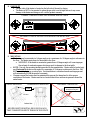
CORRECT INSTALLATION. GAS IN FROM THE LEFT SIDE
INCORRECT INSTALLATION. GAS IN FROM THE RIGHT SIDE
8. GAS INLET
• The gas inlet of the heater is located on the left side of the unit by design.
• The heater is NOT to be mounted to where the gas inlet is on the right side as it may cause
damage to the heater and doing so will void the product warranty.
9. MOUNTING
• The heater may be mounted at a 0 degree angle or at a maximum of a 30 degree angle in reference to
the floor. The heater must always be horizontal to the floor.
o WARNING: If the heater is mounted at greater than a 30 degree angle will cause improper
flue exhaust of combustion gases which may result in damage to the front grille.
• NOTE: Use only the mounting brackets provided by the manufacturer. Heater must be leveled only
on a Horizontal Axis but can be angled to a maximum of 30 degrees in reference to the floor. DO
NOT mount the heater on a vertical axis. Such installation is considered unsafe and improper and
will automatically VOID the product’s warranty.
• Clearance around the heater must be maintained for prevent fire hazard and to allow proper
ventilation of the heater. Heater must be in a location that allows uniform air pressure around the
entire heater.
`
ANGLE MOUNTED HORIZONTAL MOUNTED
HEATER MUST BE INSTALLED IN SUCH A WAY
THAT COMBUSTION EXITS THROUGH TOP VENTS
Vent
30 DEG
Radiant Heat
INCORRECT MOUNTING
OVER 30 DEG
Combustion gases exit
through the front grille.

7
• Do not locate either the gas or electrical supply line directly above the flue outlet of the heater. The
heater must be installed in a location so that it is readily accessible for servicing and have no
restriction of airflow for combustion air and exhaust flue.
! IMPORTANT !
ALL AREAS AROUND THE HEATER MUST BE CLEARED OF ANY COMBUSTIBLE MATERIALS.

8
MOUNTING CLEARANCES
Each heater must be installed such that the following “Minimum Clearance to Combustibles’ are
maintained. Combustible materials include wood, compressed paper, plant fibers, plastic, or other materials
capable of being ignited and burned. Such materials shall be considered combustible even though flame-proofed,
fire retardant treated or plastered. Additional clearance may be required for glass, painted surfaces, vinyl siding
or other materials which may be damaged by radiant or convection heat. A minimum clearance of 24 inches
above the heater must be maintained to plastics, vinyl or any other materials that may be adversely affected
by radiant or convection heat.
! WARNING !
The clearances shown below are applicable to vehicles parked below or in front of the heater(s). They
are also applicable to retractable awnings, umbrellas, pergolas, etc. whether the heater is ON or OFF. Do
not place any objects whether combustible or non-combustible within the mounting clearances specified
on the mounting instructions.
Note: Where applied, the Uniform Mechanical Code requires that all portions of overhead radiant heaters are
located at least 8 feet above the floor.
MINIMUM CLEARANCES TO COMBUSTIBLES:
Sides or Ends
Back
Above
Below
24”
12”
18”
48”

9
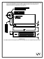
ELECTRICAL INSTRUCTIONS
To install the battery on the wireless remote control:
a) Slide out the battery cover at the back of the remote control.
b) Place the battery into the battery slot with the polarities pointing towards the appropriate polarity. Then
push the battery in. Push the ON button to verify that the red indicator turns on. Then place the face
plate back on with the Twin Eagles logo at the bottom near the LO button.
The receiver is powered by four 1.5V AA batteries located in a battery pack inside the heater component
compartment. These batteries should be adequate for the heater operation for a whole season.
To install the AC Adaptor
An AC/DC volt adapter can be used in which case the batteries will become a back-up voltage supply. The
adapter must NEVER be located inside the heater control compartment. If adapter is used, provide a 120-volt
outlet near the end of the heater but not directly above the heater.
a. Run the power lead connectors of the AC adapter through
the small hole next to the gas inlet.
b. Connect terminals of the adapter to the “POWER”
male terminals of the electronic controller, there is no
polarity. Then plug in your adapter to the 120V
power outlet.
c. The AA batteries go in the in the battery pack located
inside the component compartment. When the
adapter is used the batteries will work as a back-up.
NOTE: Always
have the battery
pack switch on
the “Latching
Solenoid” side.

10
OPERATING INSTRUCTIONS
INITIAL START UP:
1. Before you start your heater examine the heater installation to determine that:
• Areas immediately around heater including the air inlet and flue areas are free from obstructions.
• Physical support of the heater is safe, secure, adequate and sound.
• There is no obvious deterioration of the heater, gas inlet hose and AC adapter if used.
2. REMOTE CONTROL SYNCHRONIZATION & START-UP TEST:
• The remote control leaves the factory already synchronized for each heater. To verify that, with the
heater’s gas inlet valve in the CLOSED position, verify that the remote control system is working
properly.
• Push the “ON” button on the remote control. You will hear a continuous spark sound at the pilot. If
there are no sparks, replace the AA batteries with new ones. If with the new batteries there are still
no sparks, synchronization is needed. For synchronization perform the following steps.
Single heater application
a) Push-and-hold the “LEARN” button on the module for 2 seconds
until it “beeps”. NOTE: Holding for 10 seconds will clear the
module.
b) Push-and-hold the ON button on the remote and the “beep” sound
will confirm synchronization. NOTE: Holding for 10 seconds will
clear the module.
Multiple heater application
a) Push-and-hold the “LEARN” button on the module for 2 seconds until it “beeps” and then remove a
battery. Repeat same step for all heaters.
b) Install the battery only to one heater.
c) Push-and-hold the “LEARN” button until it “beeps” once and then push-and-hold the ON button on
a remote control and the next “beep” sound will confirm synchronization.
NOTE: One remote control per heater.
d) Remove a battery to that same heater.
e) Repeat steps b, c, d and e for the rest of the heaters and its individual remote controls.
f) Once the synchronization is completed for all heaters place the battery back on all heaters.
3. Check for gas leaks using soapy water at all gas connections and joint unions. NEVER use a flame to
check for leaks. (Pg 3)
4. Pilot Burner Ignition Test
a) Turn ON the gas supply to the heater.
b) Please check the environment of the gas valve for a smell of gas. If for any reason you smell or
think you smell gas, see the warning in the box below
WHAT TO DO IF YOU SMELL GAS:
• Do not try to light any appliance.
• Do not touch any electric switch; do not use any phone in your building.
• Immediately call your gas supplier from a neighbor’s phone. Follow the
gas supplier’s instructions.
• If you cannot reach your gas supplier, call the fire department.
MODULE
“LEARN”

11
c) If you do not smell gas, locate the pilot burner of the heater which is mounted at the front end of the
main burner. Make sure you have a line of sight to this pilot burner location.
d) Turn the gas heater ON by pressing the ON button on the remote control and press HI. For heaters
that are wired to an external switch, flip the switch to the ON position
e) Allow the pilot burner and main burner to burn for about 10-15 seconds.
f) Then turn the gas heater OFF and the pilot burner should shut off. It could take about 5 seconds for
the pilot flame to go completely OFF.
g) CRITERIA:
• If the pilot burner shuts-off in about 5 seconds, the gas valve is working properly.
• If the pilot burner continues to burn after the 5 seconds, please shut-off the main gas supply
line to the heater. Then immediately contact your local distributor or dealer for a repair or
replacement of the gas valve assembly
NOTES:
• Some white smoke and green flame may appear during the initial start-up of the heater but it
will dissipate with proceeding use.
• AUTO-LOCK OUT
• If the pilot continuously sparks for 60 seconds and the spark sensor doesn’t sense a
flame, it will go into safety AUTO LOCK OUT feature and shutoff the ignition
system. Check that all heaters requirements have been applied. Then push the “OFF”
button for 2 seconds to reset the system. Push the “ON” button again to light the
pilot. If the heater will not light after 3 attempts, shutoff the heater, shut-off the
heater’s manual gas inlet valve and call your qualified service agency
USING THE GAS HEATER:
a. Always test the pilot burner ignition as per Step 4 above to ensure that the gas valve is working
properly.
b. Turn the main gas supply valve to the OPEN position.
c. Push the “HI” button, then push the “ON” button, you will hear clicking sounds and will see sparks
to the igniter pilot. (Always start with HI setting during initial start-up)
d. Once the pilot is lit, the pilot will ignite the infrared burner within 4 seconds. During ignition a
smooth flame will roll down the length of the infrared burner. Flame should stabilize on the ceramic
surface. Within 60 seconds the burner will start to glow bright and radiates heat
NOTE: The ceramics portion of the infrared burner should glow bright within 60 seconds and may be
difficult to see in bright sunlight.
! WARNING !
Never attempt to manually light the burner or pilot with a match or other source of flame. Twin Eagles
heater utilizes an automatic lighting ignition.
e. HI – LOW SETTING
a. Push the “HI” button and the heater will adjust the gas flow to 37,000 BTU/Hr.
b. Push the “LO” button and the heater will adjust the gas flow to 25,000 BTU/Hr.
• SHUTTING DOWN THE HEATER
• Push “OFF” on the remote control and verify that the pilot burner and the pilot have turned off.
Should you need to shut down your heater for service or maintenance, the main gas valve next to the
heater should also be turned “OFF”.

12
PREVENTIVE MAINTENANCE
Routine maintenance should be performed at least once a year by a qualified service agency to ensure the
heater is operating properly. Overtime, particularly during long periods of not being used, the heater can
accumulate dirt, debris and cobwebs in and around the pilot and the burner. More frequent service may be
required for heaters located near waterfronts or in strong wind areas were there might be sand storms.
NOTE: It is strongly recommended that the heaters be inspected annually, before each use season.
STAINLESS STEEL & GENERAL PRODUCT CARE
To keep your Overhead Heater free of surface corrosion and in good working order, it is important to take
additional precautions under certain conditions.
If your Overhead Heater is located in corrosive conditions, such as:
• A coastal environment where corrosive salty air is present
• Near a swimming pool, hot tub or water feature with exposure to corrosive pool chemicals and/or
chlorinated water
• Areas where muriatic acid (hydrochloric acid) or other corrosive cleaning solutions are used to clean
concrete and masonry
• Areas where corrosive masonry dust and debris are created by cutting stone or mixing cements
These conditions can create a highly corrosive environment that will cause the corrosions resistant type 304
stainless steel to develop surface oxidation, corrosions or rust. Certain areas may discolor overtime. This is a
normal discoloration caused by the intense heat given off by the burners.
Twin Eagles products have been tested in saline solutions, highly chlorinated solutions and have been tested
against exposure to highly acidic foods. The test results proved the type 304 stainless steel can withstand
exposure over prolonged periods of time. However, the conditions outlined above, along with neglect, can lead
to surface corrosion or rust.
ELECTRICAL SHOCK HAZARD
Disconnect electrical power and gas supply before servicing. This heater must be connected to a
properly grounded electrical source.
SPIDER AND INSECT WARNING
Spiders and other insects can nest in the burners and orifices of this and any other outdoor products,
which causes the gas to flow from the front of the burner. This can create a dangerous condition that can cause
a fire behind the valve panel, damaging the Overhead Gas Heater and making it unsafe to operate.
Inspect the burners once a year, or if the Overhead Gas Heater has not been used for more than a month or if
any of the following conditions occur:
1. The smell of gas in conjunction with the burner flames appearing yellow.
2. The heater does not reach temperature.
3. The heater heats unevenly.
4. The burner makes popping noise.

13
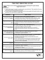
TROUBLE SHOOTING GUIDE
NEVER attempt to service the heater without disconnecting or shutting OFF its power and gas
supply from the source.
Important Notes:
a) After the initial usage it is normal to see white smoke come out the back. This eventually will go away
and it doesn’t affect the performance of the heater.
b) It is also normal to see warpage on the housing since the housing expands while heated but after it cools
back down it will come back to its original shape.
PROBLEM WHAT TO DO
Igniter sparks but pilot burner
will not ignite and igniter goes to
lock-out.
1. No gas supply to the pilot. Check if gas supply valve is turned on.
2. Air trapped in gas line (VERY COMMON DURING INITIAL START-UP). Turn on
remote control 3 times to purge air. If unsuccessful, disconnect gas hose from heater
inlet and purge air until you smell gas. Then reconnect gas hose to heater inlet.
Igniter gives very weak or slow
sparks.
1. Low battery in battery pack. Open heater control panel and replace 4 AA batteries.
2. Ground wire is not connected. With the control panel open, check if green wire is
grounded.
Remote control (transmitter) will
not communicate with heater
module (receiver)
1. Low battery in transmitter. Replace 1 lithium batteries (A23-12v)
2. Low battery in battery pack or battery pack is unpluged. Open control panel and check
if battery pack is plugged in or replace 4 AA batteries.
3. Module switch is set to OFF. Make sure module switch is set to REMOTE.
4. Remote is not synchronized with module. Refer to manual on how to synchronize
remote.
Remote control communicates
with heater but heater will beep
and no sparks to pilot.
1. Pilot sensor is damped or wet. Installation must be located in dry condition.
2. Defective pilot sensor. Replace pilot burner assembly
3. Low battery pack. Replace 4 AA batteries.
Pilot turns on and off. Burner
turns on and off
1. Windy condition. Pilot sensor senses flame inconsistently. Do not operate equipment
until wind dies down or heater is relocated to less windy condition.
2. Pilot flame is too small for flame sensing. Increase pilot flame such that flame
surrounds the pilot sensor rod.
3. Heater is installed reversed such that the pilot sensor is below the pilot flame instead of
above or even to the pilot flame. Correct installation such that the gas inlet is on the
left side of the heater for proper operation. When the gas inlet is on the left side the
pilot sensor rod is above the pilot burner.
Pilot burner stays on after heater
is turned off.
1. Defective gas valve. Contact local dealer to replace gas valve.
Heater valve will not switch from
Hi to Low and vice versa
1. Low battery pack. Replace 4 AA batteries.
2. Ground wire not connected. Connect ground wire to chassis and remove and re install
4 AA batteries to clear memory.
3. Defective gas valve. Contact local dealer to replace gas valve.
Batteries in the battery pack
drain fast.
1. The battery pack is switch to DC MOTOR instead of LATCHING SOLENOID. Make
sure that the battery pack switch is set to LATCHING SOLENOID.

14
Front grille deteriorates
1. Tip angle exceeding 30 degrees such that products of combustions vent out to the front
grille instead of out the top of the heater. Correct installation and make sure only
radiant heat passes through the front grille.
2. Windy condition. Excessive wind disrupts flow of combustion products such that
combustion products flow though the front grille instead of out the top of the heater.
Locate heater in less windy conditions.
Burner makes loud rumbling
noise during operation. Burner
does not glow and flares out
1. Damaged burner. Contact local dealer to replace burner.
Heater operates but makes
continuous beeps.
1. Module exceeds designed operating temperature. Improper installation such that
products of combustion flows through the front grille instead of out the top of heater.
This could be due to exceeding the 30 degree tip angle or windy conditions. Correct
installation such that only radiant heat passes through the front grille.
High Altitude Installation
Installation of this appliance at altitudes above 2,000 ft (610m) shall be in accordance with local codes,
or in the absence of local codes, the National Fuel Gas Code, ANSI Z223.1/NFPA 54 or National Standard of
Canada, Natural Gas and Propane Installation Code, CSA B149.4.
Installation at high altitudes may require special attention and considerations. The air at high altitudes is
thinner having less oxygen and lower atmospheric pressure, so heating and cooking are going to present specific
sets of challenges. To address such variables, appliances must be adjusted to operate at high altitudes. Generally
speaking, input ratings used for elevations up to 2,000 ft (600m) must be reduced at a rate of 4% for each 1,000
ft (300m) above sea level.
Altitude (ft.) Orifice Size (NG) Orifice Size (LP)
0’– 2,000’
36
50
For more information, please contact your Twin Eagles dealer or call Twin Eagles direct at (800) 789-
2206 or (562) 802-3488.

15
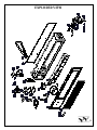
EXPLODED VIEW

16
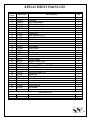
REPLACEMENT PARTS LIST
Item
Number
Part Number Part Description Qty
1
S13351
Infrared Burner
1
2
S21965
Face Panel
1
3
S21961Y
Egg Crate Assembly
1
4
S13203
Emblem, Twin Eagles
1
5
S14160
Tinnerman Barrel Clip
2
6
S13347
Pilot
1
7
S21914
Bracket, Igniter
1
8
S13357
Rubber Boot
1
9
S13348
Pilot, Orifice 0.012 LP
1
10
S13349
Pilot, Orifice 0.018 NG
1
11
S13358
Pilot, Gas line
1
12
S15108-50
Orifice #50, LP
1
13
S15108-36
Orifice #36, NG
1
14
S12407
Flex Tubing
1
15
S16240
Orifice Elbow
2
16
S21959
Baffle Venturi
1
17
S15325-36
Gas Hose
1
18
S21964
Cover Module
1
19
S21944
Bracket, Control Module
1
20
S16171
Control Module
1
21
S16175
Remote Control, Black
1
22
S16174
AC Adapter (Optional)
1
23
S12654
Coupling, 3/8 M Flare x 3/8 MPT
1
24
S15113
Valve, Dual Stage
1
25
S15114
Rate Screw Orifice, LP
1
26
S15115
Rate Screw Orifice, NG
1
27
S21946
Mount Plate
1
28
S16173
Battery Pack
1
29
S21911
Battery Pack, S-Bracket
1
30
S21943
Bracket, Battery Pack
1
31
S21963
Cover, Battery Pack
1
32
S21960
Cover, Case, 48
1
33
S21945
Post Bracket
1
Non-Shown Parts
S16172
Wire Harness
1
La page est en cours de chargement...
La page est en cours de chargement...
La page est en cours de chargement...
La page est en cours de chargement...
-
 1
1
-
 2
2
-
 3
3
-
 4
4
-
 5
5
-
 6
6
-
 7
7
-
 8
8
-
 9
9
-
 10
10
-
 11
11
-
 12
12
-
 13
13
-
 14
14
-
 15
15
-
 16
16
-
 17
17
-
 18
18
-
 19
19
-
 20
20
-
 21
21
-
 22
22
-
 23
23
-
 24
24


Twin Eagles Gas Infrared Heater Le manuel du propriétaire
- Catégorie
- Barbecues
- Taper
- Le manuel du propriétaire
- Ce manuel convient également à
dans d''autres langues
Documents connexes
-
Twin Eagles Side Burner Le manuel du propriétaire
-
Twin Eagles TESB132-C Le manuel du propriétaire
-
-
-
-
-
Autres documents
-
DCS DRH-48N Manuel utilisateur
-
HeatStar HSRP37GL Outdoor Patio Heater Le manuel du propriétaire
-
Perel FT10CN Manuel utilisateur
-
Rinnai RC98HPI Guide d'installation
-
-
-
-
Rinnai REU-VC2837WD-US-N Mode d'emploi
-
-
Rinnai TANKLESS WATER HEATER V53E Manuel utilisateur