Norcold N2090 Guide d'installation
- Catégorie
- Frigos
- Taper
- Guide d'installation

Refrigerator
N2000 Series
Install Manual
Norcold, Inc.
P.O. Box 4248
Sidney, OH 45365-4248
Norcold Customer Service Dept.
Telephone: 800-543-1219
Fax: 734-769-2332
Website: www.norcold.com


Index
ENGLISH 3

2
Contents
1. Introduction ..................................................................................................... 3
2. Symbols ............................................................................................................ 3
3. Regulations and Standards .............................................................................. 3
4. Serviceability .................................................................................................... 4
5. Position and placement ................................................................................... 5
6. Prepare for installation (N2090 only)............................................................... 6
7. Connecting electrical supplies.......................................................................... 9
8. Mounting the refrigerator ............................................................................. 14
9. Ventilation...................................................................................................... 17
10. Installing the door panel .............................................................................. 21
11. Door Conversion .......................................................................................... 24
12. Warranty and servicing ................................................................................ 26
EN
Original Installation Manual

3
1. Introduction
This is the installation manual for the Norcold N2000 series refrigerator. The manual is meant for
qualified installers who will install the refrigerator in a mobile leisure vehicle. Read the information
and instructions carefully and follow them strictly to install the refrigerator safely and correctly.
Also read the warnings in the user manual before testing the refrigerator after installation.
Our policy is one of continuous development and improvement. Specifications and illustrations
may change subsequent to publication.
If the appliance is not installed in accordance with national regulations, rules and
standards this will void the warranty.
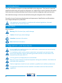
2. Symbols
Key to symbols:
Warning.
Risk of serious injury and/or damage.
Caution.
Risk of injury and/or damage.
Attention.
Important information.
Note.
Additional information.
3. Regulations and Standards
Do not modify this appliance unless the modification is authorized and carried out by
the manufacturer or their agent.
For installations which need an electric outlet that is energized by an external power
source, the refrigerator must be electrically grounded as written in local codes or the
National Electrical code, NFPA 70.
Use only genuine and approved parts and materials.
Wear the correct Personal Protective Equipment during the installation. Also follow the
applicable safety regulations.
Electrical appliances should only be installed by qualified and certified professionals.
The electronic connections must be installed in accordance with the latest technical
regulations.

4
Make sure the refrigerator is transported and handled in the upright position, or on its
side with the electronics facing down as depicted in the section Installing door panel.
After the refrigerator has been transported and/or been laid on its side, let the
refrigerator stay upright for 30 minutes before switching on.
Install the refrigerator in accordance with the local/national laws.
Do not spray liquids near electrical outlets, connections, or refrigerator components.
Many liquids are electrically conductive and can cause a shock hazard, electrical shorts
and in some case fire.
Never open or damage the cooling system at the back or on the inside of the refrigerator.
The cooling system is pressurized and contains flammable substances.
The performance of the refrigerator may be affected by adjacent heat sources such as an
oven or stove. Protect the refrigerator against any heat sources by fitting insulation.
Never reposition or change the electronic components.
In order to prevent the risk of fire in the event of uncontrolled leakage of the refrigerant
system, make sure that the refrigerant charge per net room volume does not exceed
0.0005lb/ft
3
. Net room volume is defined as the gross room volume minus the volume of
any product, equipment, or objects located in the living area. The refrigerant charge
amount can be found on the serial label.
Make sure no equipment that produces sparks or flames is installed close to the cooling
system.
Any error messages coming from the refrigerator should not disturb the driver. For
example: flashing of the display to indicate an error while driving.
Do not use the drawer as a step or ladder.
The refrigerator is intended to be used in a recreational vehicle. The refrigerator is not
suited for use other than in a recreational vehicle.
4. Serviceability
The installer of Norcold products is responsible for proper installation to ensure the correct
Functionality and serviceability of the appliance. In terms of serviceability, this means that a
dealer or an authorized Norcold service partner must be able to remove and re−install the
Norcold products within the time that is allowed according to the Norcold time−list, using
standard tools and equipment.
This is to claim any warranty during the period of 1 years after purchase date. In case of any queries
on this subject, please contact the Norcold local service representative before installing the product.

5
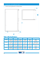
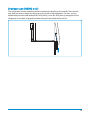
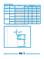
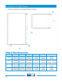
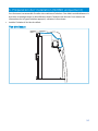
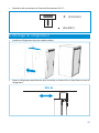
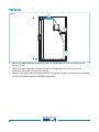
5. Position and placement
•
Use the mounting dimensions as shown below.
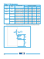
Table 1: Mounting dimensions
Model H W D FL FH A
N2090
38.7in
[982mm]
16.5in
[420mm]
19.9in
[506mm]
0.8in
[21mm]
0.8in
[20mm]
0.8in
[20mm]
N2152 59.2in
[1504mm]
16.5in
[420mm]
22.3in
[567mm]
1.7in
[42mm]
1.1in
[28mm]
1.6in-2.4in
[40mm−60mm]
N2160 49.2in
[1249mm]
20.7in
[527mm]
22.2in
[563mm]
2.2in
[55mm]
0.1in
[3mm]
0.2in
[5mm]
N2175 49.2in
[1249mm]
20.7in
[527mm]
23.7in
[613mm]
2.2in
[55mm]
0.1in
[3mm]
0.2in
[5mm]
FL
H
A
FH

6
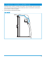
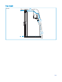
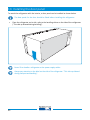
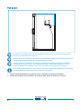
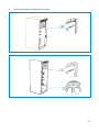
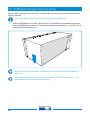
6. Prepare for installation (N2090 only)
Installing insulation material is strongly recommended. It will considerably reduce the emitted
noise and protects against heating up from outside the vehicle. For information on the correct
type of insulation, contact the supplier.
•
Install insulation on the back of the chassis.
Top model

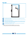
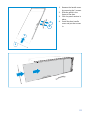
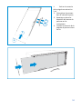
7
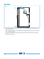
Floor model
The insulation material should be left exposed and not covered by paneling to prevent
unwanted reflection of noise.
Ensure that the insulation material is able to handle the temperatures and the mechanical
loading expected during normal use.
Ensure that the insulation material does not diminish the minimal ventilation dimensions
of the air ducts. Glued insulation material might detach over time and block the airways.
Overheating of the system might be a result.
For the correct type of insulation, it is advised to use a polyurethane noise absorption
panel with open cell structure, or similar.
•
Make a cut−out in the roof panel, exposing the insulation material.
•
Seal any gaps between furniture and chassis to prevent noise emission.

8
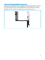
Drainage tube (N2090 only)
This refrigerator has the possibility to drain condensation directly to the outside. Then the end
user does not have to empty the drip tray via the inside of the refrigerator. For this, you can
extend with your own tube (external Ø 0.35in [9mm], inner Ø 0.20in [5mm]) coming out of the
refrigerator at the back, and guide this tube directly to the outside of the vehicle.

9
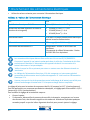
7. Connecting electrical supplies
•
Use the following values to connect the power supply.
Table 2: Power supply values
The electrical connections must comply with IEC/UL/EN60335−1.
Connect the device to an on-board battery in the vehicle. This battery should be
exclusively intended for powering on−board devices. Connecting to the engine battery is
not suitable.
Ensure that wires can't come into contact with hot or sharp parts.
The 12V power supply wiring should incorporate a general main switch that enables all
pole disconnection of the 12V appliances from the 12V power supply source.
Ensure that the Battery Discharge Protection Circuit is used to prevent damage to the 12V
battery when the battery is at low charge.
The factory setting for the cut−in/cut−out voltage is 10.4V (cut−out) and 11.7V (cut−in). For trailer
applications without on−board battery, this setting can be changed to 11.3V (cut−out) and 12.5V
(cut−in).
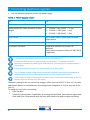
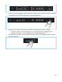
To change the cut−in/cut−out setting:
•
Open the door.
•
Unlock the control panel, if applicable, by pressing the fresh food, frozen food or night mode
area. Hold it for a few seconds until the icons blink twice to be able to adjust the setting.
DC 12V
Power requirement 12V DC 10.4−16.0V at the refrigerator
Cable dimensions (Cable thickness vs cable
length)
•
14 AWG =< 8ft [2.5mm
2
= ‹ 2.5m]
•
12 AWG =< 13ft [4mm
2
= ‹ 4m]
•
10 AWG =< 20ft [6mm
2
= ‹ 6m]
Fuse current 15A in power supply system near the power
supply source
DC supply
Red cable (+) and white cable (−)
12V power connector
Refrigerator: Stocko VV 2041.100-G or
equivalent
Supply cable counterpart: Stocko VV 2041.200
-
G
or equivalent

10
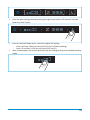
•
Open the extra settings mode by pressing the night mode area for 10 seconds. The fresh
food icons blink 2 times.
•
Press on the fresh food area for 1 second to adjust the setting:
− Icons 1 and 5 on: 10.4V (cut−out) and 11.7V (cut−in) (factory setting).
− Icons 2, 3 and 4 on: 11.3V (cut−out) and 12.5V (cut−in).
•
After a few seconds, the control panel will save the settings and go to the locked stand−by
mode.

11
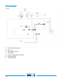
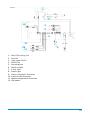
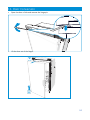
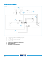
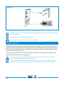
Wiring diagram:
1.
Main PCBA cooling unit
2.
Fuse 15 A
3.
Input power 12V DC
4.
LED module
5.
Interior refrigerator thermistor
6.
Display module
7.
Fan cooling unit
N2090
1
2
3
4
7
6
5
5

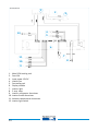
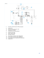
12
1.
Main PCBA cooling unit
2.
Fuse 15A
3.
Input power 12V DC
4.
Interior Fan
5.
Fan cooling unit
6.
Display module
7.
2−way valve
8.
Interior light
9.
Interior refrigerator thermistor
10.
Interior freezer thermistor
11.
Ambient temperatures thermistor
12.
LED module
N2152
1
2
3
12
4
5
6
11
10
9
8
7
9

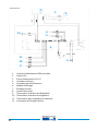
13
1.
Main PCBA cooling unit
2.
Fuse 15A
3.
Input power 12V DC
4.
Interior Fan
5.
Fan cooling unit
6.
Display module
7.
Interior light
8.
2−way valve
9.
Interior refrigerator thermistor
10.
Interior freezer thermistor
11.
Ambient temperatures thermistor
12.
Interior light switch
N2160/N2175
1
2
3
12
4
5
6
11
10
9
7
8

14
•
Connector layout of the input power 12V DC:
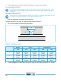
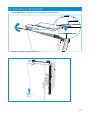
8. Mounting the refrigerator
•
Mount the refrigerator in stable furniture.
•
Place the refrigerator partly into the furniture, allowing 4in [10cm] free at the top of the
refrigerator.
(RED)
(WHITE)
4 in

15
•
Connect the power connector with the 12V power connector in the vehicle.
For models N2090 and N2152:
It is advised to have the power supply in the vehicle to be routed via the roof. In this
way an over−length of cable is not needed and the power supply cable cannot block
the airways.
For models T2160 and T2175:
Connect the 12V power connector before any furniture is mounted. Make sure that the
12V cable is not trapped between the refrigerator and furniture.
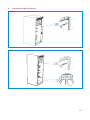
•
Slide the refrigerator to the back of the furniture.
The space holders on the back will stop the fridge at correct position.
•
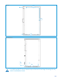
Use a screw suitable for below hole dimensions.
Table 4: Hole dimensions
N2090 N2152 N2160/N2175
side side floor side floor
A
Ø 0.35in
[9mm]
Ø 0.35in
[9mm]
Ø 0.35in
[9mm]
Ø 0.35in
[9mm]
Ø 0.20in
[5mm]
B
0.24in
[6mm]
0.24in
[6mm]
1.34in
[34mm]
0.24in
[6mm]
0.43in
[11mm]
C
Ø 0.16in
[4.0mm]
Ø 0.18in
[4.5mm]
Ø 0.18in
[4.5mm]
Ø 0.18in
[4.5mm]
Ø 0.20in
[5mm]
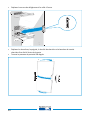
•
Fix the refrigerator in place with the screws, using the pre−drilled positions in the cabinet.
A
B

16
•
Use the white caps for finishing.
N2152
N2090

17
Ensure that the furniture paneling is able to handle the forces created by the
connection.
Do not screw into the refrigerator cabinet.
The refrigerators are prepared for flush build in.
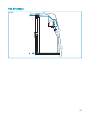
9. Ventilation
The refrigerator performance depends on good ventilation. Ventilation for N2090 and N2152 takes
place through the front vent openings in the refrigerator. Ambient air enters through the bottom
at the front and is forced through the cooling system. Heated air is pushed away via the top vent
opening.
Ventilation for the N2160 and N2175 takes place through the integrated and insulated cooling unit
box at the bottom part of the refrigerator.
Ensure that the top and bottom vent openings are not obstructed and are able to vent
freely.
The bottom vent opening has no filter. For all models, placing a filter is not needed and
might lead to poor performance.
N2160/N2175

18
Top model
N2090
2
3
1
La page est en cours de chargement...
La page est en cours de chargement...
La page est en cours de chargement...
La page est en cours de chargement...
La page est en cours de chargement...
La page est en cours de chargement...
La page est en cours de chargement...
La page est en cours de chargement...
La page est en cours de chargement...
La page est en cours de chargement...
La page est en cours de chargement...
La page est en cours de chargement...
La page est en cours de chargement...
La page est en cours de chargement...
La page est en cours de chargement...
La page est en cours de chargement...
La page est en cours de chargement...
La page est en cours de chargement...
La page est en cours de chargement...
La page est en cours de chargement...
La page est en cours de chargement...
La page est en cours de chargement...
La page est en cours de chargement...
La page est en cours de chargement...
La page est en cours de chargement...
La page est en cours de chargement...
La page est en cours de chargement...
La page est en cours de chargement...
La page est en cours de chargement...
La page est en cours de chargement...
La page est en cours de chargement...
La page est en cours de chargement...
La page est en cours de chargement...
La page est en cours de chargement...
La page est en cours de chargement...
La page est en cours de chargement...
-
 1
1
-
 2
2
-
 3
3
-
 4
4
-
 5
5
-
 6
6
-
 7
7
-
 8
8
-
 9
9
-
 10
10
-
 11
11
-
 12
12
-
 13
13
-
 14
14
-
 15
15
-
 16
16
-
 17
17
-
 18
18
-
 19
19
-
 20
20
-
 21
21
-
 22
22
-
 23
23
-
 24
24
-
 25
25
-
 26
26
-
 27
27
-
 28
28
-
 29
29
-
 30
30
-
 31
31
-
 32
32
-
 33
33
-
 34
34
-
 35
35
-
 36
36
-
 37
37
-
 38
38
-
 39
39
-
 40
40
-
 41
41
-
 42
42
-
 43
43
-
 44
44
-
 45
45
-
 46
46
-
 47
47
-
 48
48
-
 49
49
-
 50
50
-
 51
51
-
 52
52
-
 53
53
-
 54
54
-
 55
55
-
 56
56


Norcold N2090 Guide d'installation
- Catégorie
- Frigos
- Taper
- Guide d'installation
dans d''autres langues
- English: Norcold N2090 Installation guide
Documents connexes
-
Norcold NRF60 Manuel utilisateur
-
 NORCOLD INC NRF60 Manuel utilisateur
-
-
-
-
-
Norcold N4104/ N4141/ N4150 Le manuel du propriétaire
-
 NORCOLD INC N3104AGR Manuel utilisateur
-
-


