Technics SU-G700 Operating Instructions Manual
- Taper
- Operating Instructions Manual

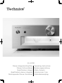
SU-G700
Stereo Integrated Amplifier Operating Instructions
Stereo-Vollverstärker Bedienungsanleitung
Amplificateur intégré Mode d’emploi
Amplificatore stereo integrato Istruzioni per l’uso
Geïntegreerde Stereo Versterker Gebruiksaanwijzing


03
Music is borderless and timeless, touching people’s
hearts across cultures and generations.
Each day the discovery of a truly emotive experience
from an unencountered sound awaits.
Let us take you on your journey to rediscover music.

04

05
Delivering the Ultimate Emotive Musical
Experience to All
At Technics we understand that the listening experience is not
purely about technology but the magical and emotional relationship
between people and music.
We want people to experience music as it was originally intended
and enable them to feel the emotional impact that enthuses and
delights them.
Through delivering this experience we want to support the
development and enjoyment of the world’s many musical cultures.
This is our philosophy.
With a combination of our love of music and the vast high-
end audio experience of the Technics team, we stand committed
to building a brand that provides the ultimate emotive musical
experience by music lovers, for music lovers.
Director
Michiko Ogawa

06
(06)
Thank you for purchasing this product.
Please read these instructions carefully before using this product, and save this manual for future use.
• About descriptions in these operating instructions
- Pages to be referred to are indicated as “ ○○”.
- The illustrations shown may differ from your unit.
For the United Kingdom and Ireland customer
Sales and Support Information
Customer Communications Centre
• For customers within the UK: 0333 222 8777
• For customers within Ireland: 01 447 5229
• Monday–Friday 9:00 am – 5:00 pm, (Excluding public holidays).
• For further support on your product, please visit our website: www.technics.com/uk/
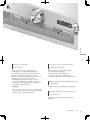
High-Quality Audio Technologies
Employed including JENO Engine
and LAPC
The JENO Engine transmits and processes audio
signals in full digital and with minimal jitter from
the input stage to the power stage. The LAPC
conducts speaker load adaptive phase calibration
to achieve ideal gain and phase characteristics
for any type of speaker. Also, a unique, high-
precision PWM conversion circuit is used for
PWM conversion, which is important for sound
quality.
Three-section Configuration
In integrated amplifiers, there are a variety of
circuits such as circuits handling the micro-
signals of input, circuits handling large current,
etc. SU-G700 uses a three-section construction
with partitions installed between the circuit
blocks according to the signal level handled. This
eliminates interference between circuit blocks,
thus achieving clear sound quality.
High Rigidity Aluminum Cabinet
The high-rigidity metal double chassis features
a steel-plate inner chassis and a steel-plate
outer chassis to reduce vibration and noise that
degrade the purity of sound.
Features

English
07
(07)
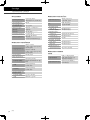
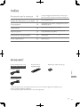
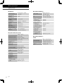
Table of contents
Safety precautions 08
Please carefully read the “Safety precautions” of this
manual before use.
Control reference guide 10
This unit, Remote control
Connections 14
Speaker connection, AC mains lead connection
Operations 16
Playing back connected devices
Settings 24
Other settings, Using output correction function
(LAPC)
Troubleshooting 30
Before requesting service, read the troubleshooting.
Others 33
Specifications, etc.
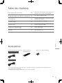
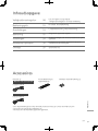
Accessories
AC mains lead (2)
K2CM3YY00041
Except for Switzerland
K2CS3YY00033
For Switzerland
Remote control (1)
N2QAYA000143
Batteries for remote control (2)
• Product numbers provided in these operating instructions are correct as of February 2017.
• These may be subject to change.
• Do not use AC mains lead with other equipment.

08
Safety precautions
(08)
Warning
Unit
• To reduce the risk of fire, electric shock or
product damage,
- Do not expose this unit to rain, moisture,
dripping or splashing.
- Do not place objects filled with liquids, such
as vases, on this unit.
- Use only the recommended accessories.
- Do not remove covers.
- Do not repair this unit by yourself. Refer
servicing to qualified service personnel.
- Do not let metal objects fall inside this unit.
- Do not place heavy items on this unit.
AC mains lead
• To reduce the risk of fire, electric shock or
product damage,
- Ensure that the power supply voltage
corresponds to the voltage printed on this
unit.
- Insert the mains plug fully into the socket
outlet.
- Do not pull, bend, or place heavy items on the
lead.
- Do not handle the plug with wet hands.
- Hold onto the mains plug body when
disconnecting the plug.
- Do not use a damaged mains plug or socket
outlet.
• The mains plug is the disconnecting device.
Install this unit so that the mains plug can be
unplugged from the socket outlet immediately.
• Ensure the earth pin on the mains plug is
securely connected to prevent electrical shock.
- An apparatus with CLASS I construction shall
be connected to a mains socket outlet with a
protective earth connection.
Caution
Unit
• Do not place sources of naked flames, such as
lighted candles, on this unit.
• This unit may receive radio interference caused
by mobile telephones during use. If such
interference occurs, please increase separation
between this unit and the mobile telephone.
• This unit is intended for use in moderate and
tropical climates.
• Do not put any objects on this unit. This unit
becomes hot while it is on.
• Do not touch the top surface of this unit. This
unit becomes hot while it is on.
Placement
• Place this unit on an even surface.
• To reduce the risk of fire, electric shock or
product damage,
- Do not install or place this unit in a bookcase,
built-in cabinet or in another confined space.
Ensure this unit is well ventilated.
- Do not obstruct this unit’s ventilation
openings with newspapers, tablecloths,
curtains, and similar items.
- Do not expose this unit to direct sunlight, high
temperatures, high humidity, and excessive
vibration.
• Ensure that the placement location is sturdy
enough to accommodate the weight of this unit
( 34).
• Do not lift or carry this unit by holding the
knobs. Doing so may cause this unit to fall,
resulting in personal injury or malfunction of
this unit.

English
09
Safety precautions
(09)
Battery
• Danger of explosion if battery is incorrectly
replaced. Replace only with the type
recommended by the manufacturer.
• Mishandling of batteries can cause electrolyte
leakage and may cause a fire.
- Remove the battery if you do not intend to
use the remote control for a long period of
time. Store in a cool, dark place.
- Do not heat or expose to flame.
- Do not leave the battery(ies) in a car exposed
to direct sunlight for a long period of time
with doors and windows closed.
- Do not take apart or short circuit.
- Do not recharge alkaline or manganese
batteries.
- Do not use batteries if the covering has been
peeled off.
- Do not mix old and new batteries or different
types at the same time.
• When disposing of the batteries, please contact
your local authorities or dealer and ask for the
correct method of disposal.
Installation
Turn off all equipment before connection and
read the appropriate operating instructions.
For the United Kingdom and Ireland
customer
Caution for AC Mains Lead
(For the AC mains plug of three pins)
For your safety, please read the following text
carefully.
This appliance is supplied with a moulded three
pin mains plug for your safety and convenience.
A 10-ampere fuse is fitted in this plug.
Should the fuse need to be replaced please
ensure that the replacement fuse has a rating of
10-ampere and that it is approved by ASTA or
BSI to BS1362.
Check for the ASTA mark
or the BSI mark
on the body of the fuse.
If the plug contains a removable fuse cover you
must ensure that it is refitted when the fuse is
replaced.
If you lose the fuse cover the plug must not be
used until a replacement cover is obtained.
A replacement fuse cover can be purchased from
your local dealer.
Before use
Remove the connector cover.
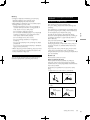
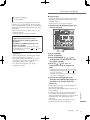
How to replace the fuse
The location of the fuse differ according to
the type of AC mains plug (figures A and B).
Confirm the AC mains plug fitted and follow the
instructions below.
Illustrations may differ from actual AC mains
plug.
1. Open the fuse cover with a screwdriver.
Figure A Figure B
Fuse cover
2. Replace the fuse and close or attach the fuse
cover.
Figure A Figure B
Fuse
(10 ampere)
Fuse
(10 ampere)

10
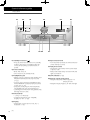
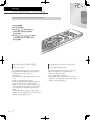
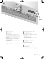
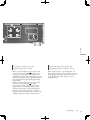
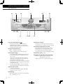
Control reference guide
This unit
(10)
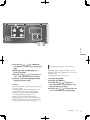
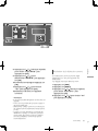
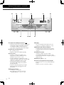
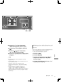
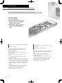
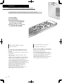
01 Standby/on button ( )
• Press to switch the unit from on to standby
mode or vice versa. In standby mode, the
unit is still consuming a small amount of
power.
02 Power indicator
• Blue: The unit is on.
• Off: The unit is in standby mode.
03 Headphones jack
• When a plug is connected, the speakers and
PRE OUT terminals do not output sound.
( 22)
• Sound is not output from headphones jack
while “MAIN IN” is selected as input source
of this unit. ( 20)
• Excessive sound pressure from earphones
and headphones can cause hearing loss.
• Listening at full volume for long periods may
damage the user’s ears.
04 Volume knob
• -- (min), 1 to 100 (max)
• To display the volume, set “VOLUME
Display” to “On”. ( 25)
05 Display
• Information such as input source, etc. is
displayed. ( 32)
06 Input selector knob
• Turn this knob clockwise or anticlockwise to
switch the input source.
07 Peak power meter
• Display the output level. 100 % is the rated
output ( 34).
• Peak power meter does not work while the
light is turned off.
08 LAPC indicator ( 26)
09 Remote control signal sensor
• Reception distance: Within approx. 7 m
directly in front
• Reception angle: Approx. 30° left and right

11
English
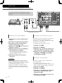
Control reference guide
(11)
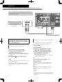
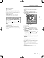
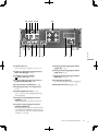
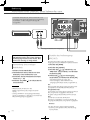
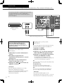
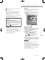
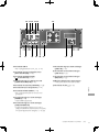
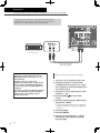
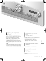
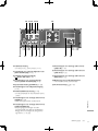
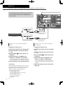
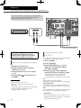
10 USB-B terminal
• For connecting to a PC, etc. ( 17)
11 Optical digital input terminal
(OPT1 IN/OPT2 IN) ( 16)
12 UPDATE terminal (USB-A)
(
DC 5 V 500 mA) ( 27)
13 Coaxial digital input terminals
(COAX1 IN/COAX2 IN) ( 16)
14 System terminal (CONTROL) ( 28)
15 Speaker output terminals ( 14)
16 PHONO EARTH terminal ( 18)
• For connecting the ground wire of a
turntable.
17 Analogue audio input terminals (PHONO)
( 18)
• MM cartridges are supported.
18 Analogue audio input terminals
(LINE2 IN/MAIN IN)
• These input terminals are combined with
LINE2 IN and MAIN IN. Switch the function
according to the connected equipment.
( 19, 20)
19 Analogue audio input terminals (LINE1 IN)
( 19)
20 Analogue audio output terminals
(LINE OUT) ( 23)
21 Analogue audio output terminals
(PRE OUT) ( 22)
22 Product identification marking
• The model number is indicated.
23 AC IN terminal (
) ( 15)

12
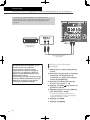
Control reference guide
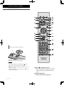
Remote control
(12)
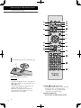
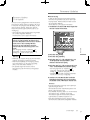
Using the remote control
2
1
R03/LR03, AAA
(Alkaline or manganese batteries)
Note
• Insert the battery so the terminals (
and
) match those in the remote control.
• Point it at the remote control signal sensor on
this unit. ( 10)
• Keep the batteries out of reach of children to
prevent swallowing.
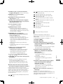
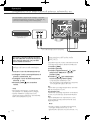
01 [AMP
]: Standby/on button
• Press to switch the unit from on to standby
mode or vice versa. In standby mode, the
unit is still consuming a small amount of
power.
02 [AMP]/[NWP]/[CD]:
Select the device to be operated

13
English
Control reference guide
(13)
03 [>INPUT<]: Switch the input source
( 16, 17, 18, 19, 20)
04 [MENU]: Enter menu ( 18, 19, 20, 21)
*
05 [SETUP]: Enter setup menu ( 24)
*
06 [LAPC]: Measure the output signal of the
amplifier when speakers are connected,
and correct its output ( 26)
07 [+VOL-]: Adjust the volume
• Volume range: -- (min), 1 to 100 (max)
08 [MUTE]: Mute the sound
• Press [MUTE] again to cancel. “MUTE” is
also cancelled when you adjust the volume
with this unit or when you turn the unit to
standby.
09 [DIMMER]: Adjust the brightness of the
peak power meter light, display, etc.
• When the display is turned off, it will
light up for a few seconds only when you
operate this unit. Before the display turns
off, “Display Off” will be displayed for a few
seconds.
• Press repeatedly to switch the brightness.
• Peak power meter does not work while the
light is turned off.
10 [INFO]: View content information
*
• Press this button to display sampling
frequency and other information. (The
information varies depending on the input
source.)
11 [
], [ ], [ ], [ ]/[OK]: Selection/OK
*
12 [RETURN]: Return to the previous display
*
*
: Press [AMP] first to operate this unit. (The
remote control may work for other Technics
devices and may not for this unit when
pressing [NWP] or [CD].)
■ Buttons that work for Technics devices
supporting system control function
The remote control of this unit also works for
Technics devices supporting system control
function (Network Audio Player, Compact Disc
Player, etc.). For information on the operations of
the devices, please also refer to their operating
instructions.
01
[ ] Standby/on switch for the Compact
Disc Player
02
[ ] Standby/on switch for the Network
Audio Player
03
Select the device to be operated
04
Select the input source of the Network
Audio Player
05
Turn on/off Direct mode
06
Turn on/off Re-master
07
Playback control buttons
08
Numeric buttons, etc.
09
Playback control buttons
Remote control mode
When other equipment responds to the supplied
remote control, change the remote control
mode.
• The factory default is “Mode 1”.
1 Press [AMP].
2 Press [SETUP].
3 Press [
], [ ] repeatedly to select
“Remote Control” and then press
[OK].
• The current remote control mode of this unit
is displayed for a few seconds.
4 When “Set Mode 1/2” is displayed,
change the remote control mode of
the remote control.
To set “Mode 1”:
Press and hold [OK] and [1] for at least 4
seconds.
To set “Mode 2”:
Press and hold [OK] and [2] for at least 4
seconds.
5 Point the remote control at this unit,
and press and hold [OK] for at least 4
seconds.
• When the remote control mode is changed,
the new mode will appear on the display for
a few seconds.
■ When “Remote 1” or “Remote 2” is
displayed
When “Remote 1” or “Remote 2” is displayed,
the remote control modes of this unit and
remote control are different. Perform step 3
above.

14
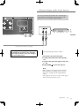
Connections
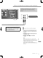
Speakers/AC mains lead
(14)
• Use only the supplied AC mains lead.
• Do not connect the AC mains lead until all other connections are complete.
• Insert the plugs of the cables to be connected all the way in.
• Do not bend cables at sharp angles.
• To optimise the audio output, you can measure the amplifier output signal and correct its
output when it is connected to the speakers. ( 26)
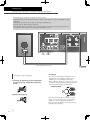
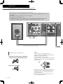
Speaker cable (not supplied)
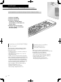
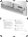
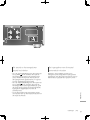
Speaker connection
1 Turn the knobs to loosen them, and
insert the core wires into the holes.
2 Tighten the knobs.
Note
• When the connections are completed, pull the
speaker cables lightly to check that they are
connected firmly.
• Be careful not to cross (short-circuit) or reverse
the polarity of the speaker wires as doing so
may damage the amplifier.
DO NOT
• Wire the polarity (+/-) of the terminals correctly.
Not doing so may adversely affect stereo
effects or cause malfunction.
• For details, refer to the operating instructions of
the speakers.

15
English
Connections
(15)
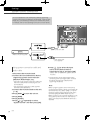
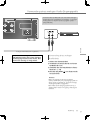
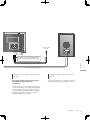
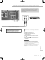
AC mains lead connection
Connect only after all other connections are
completed.
Note
• This unit consumes a small amount of AC power
( 34) even when the unit is in standby mode.
Remove the plug from the main electrical outlet
if you will not be using the unit for an extended
period of time. Place the unit so the plug can be
easily removed.
Speaker cable (not supplied)
AC mains lead (supplied)
To a household
mains socket
Insert the AC mains lead up to a
point just before the round hole.
Speaker output correction (LAPC)
You can make the optimum adjustment
according to your own speakers. ( 26)

16
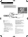
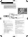
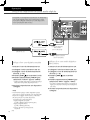
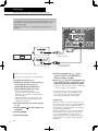
Operations
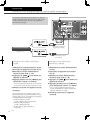
Using digital audio output device
(16)
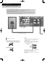
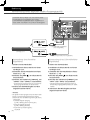
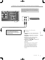
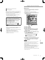
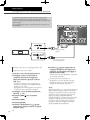
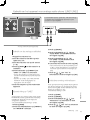
Using coaxial digital cable
1 Disconnect the AC mains lead.
2 Connect this unit and a CD player, etc.
3 Connect the AC mains lead to this unit.
( 15)
4 Press [AMP
] to turn this unit on.
5 Press [>INPUT<] repeatedly to select
“COAX1” or “COAX2”.
• You can also select the input source by
turning the input selector knob on the unit.
6 Start playback on the connected
device.
Note
• The digital audio input terminals of this unit can
only detect the following linear PCM signals.
For details, refer to the operating instructions of
the connected device.
- Sampling frequency:
Coaxial digital input
32/44.1/48/88.2/96/176.4/192 kHz
Optical digital input
32/44.1/48/88.2/96 kHz
- Number of quantisation bits:
16/24 bit
You can connect the CD player, etc. with coaxial digital
cable (not supplied)/optical digital audio cable (not
supplied) to this unit and play back music.
Optical digital audio cable
(not supplied)
CD player, etc.
Coaxial digital cable
(not supplied)
Using optical digital audio cable
1 Disconnect the AC mains lead.
2 Connect this unit and a CD player, etc.
3 Connect the AC mains lead to this unit.
( 15)
4 Press [AMP
] to turn this unit on.
5 Press [>INPUT<] repeatedly to select
“OPT1” or “OPT2”.
• You can also select the input source by
turning the input selector knob on the unit.
6 Start playback on the connected
device.

17
English
Operations
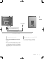
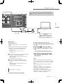
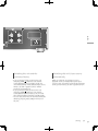
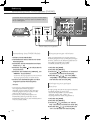
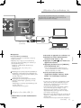
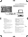
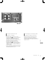
Using PC, etc.
(17)
You can connect the PC, etc. or another device with
USB 2.0 cable (not supplied) to this unit and play back
music.
■ Preparation
Connecting to a PC
• Before connecting to a PC, follow the steps
below.
• Refer to the following for the recommend OS
versions for your PC (as of February 2017):
- Windows 7, Windows 8, Windows 8.1,
Windows 10
- OS X 10.7, 10.8, 10.9, 10.10, 10.11,
macOS 10.12
Download and install the dedicated USB driver
to the PC. (Only for Windows OS)
• Download and install the driver from the
website below.
www.technics.com/support/
Download and install the dedicated app
“Technics Audio Player” (free of charge) on
your PC.
• Download and install the app from the
website below.
www.technics.com/support/
Using USB 2.0 cable
1 Disconnect the AC mains lead.
2 Connect this unit and a PC, etc.
3 Connect the AC mains lead to this unit.
( 15)
4 Press [AMP
] to turn this unit on.
5 Press [>INPUT<] repeatedly to select
“PC”.
• You can also select the input source by
turning the input selector knob on the unit.
6 Start playback using the dedicated
app “Technics Audio Player” on the
connected PC.
Note
• When connecting an audio device with USB-
DAC output terminal such as ST-G30, etc., refer
to the operating instructions of the connected
device.
• About supported format, refer to “Format
support”. ( 35)
• Windows is a trademark or a registered
trademark of Microsoft Corporation in the
United States and other countries.
• Mac and OS X are trademarks of Apple Inc.,
registered in the U.S. and other countries.
• macOS is a trademark of Apple Inc.
PC, etc.
USB 2.0 cable
(not supplied)
Audio device with USB-DAC output
terminal such as ST-G30, etc.

18
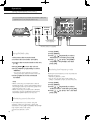
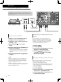
Operations
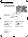
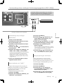
Using turntable (PHONO)
(18)
Using PHONO cable
1 Disconnect the AC mains lead.
2 Connect this unit and a turntable.
3 Connect the AC mains lead to this unit.
( 15)
4 Press [AMP
] to turn this unit on.
5 Press [>INPUT<] repeatedly to select
“PHONO”.
• You can also select the input source by
turning the input selector knob on the unit.
6 Start playback on the connected
turntable.
Note
• When connecting a turntable with a built-in
PHONO equalizer, connect the PHONO cable to
the analogue audio input terminals (LINE1 IN or
LINE2 IN) of this unit. ( 19)
• When connecting a turntable with a PHONO
earth lead, connect the PHONO earth lead to
the PHONO EARTH terminal of this unit.
Minimising sound distortion
If sound distortion occurs when using the
analogue audio input terminals, setting the
attenuator to “On(-3dB)”/”On(-6dB)”/”On(-10dB)”
may improve the sound quality.
• The factory default is “Off”.
You can connect the turntable with PHONO cable (not
supplied) to this unit and play back music.
PHONO cable (not supplied)
PHONO earth lead
(not supplied)
Turntable
1 Press [AMP].
2 Press [MENU].
3 Press [
], [ ] repeatedly to select
“Attenuator” and then press [OK].
4 Press [
], [ ] to select “On(-3dB)”/
”On(-6dB)”/”On(-10dB)” and then
press [OK].
Reducing low frequency noise
Reduces the low frequency noise caused by the
warpage of record.
• The factory default is “Off”.
• You can also set this menu while “LINE1” or
“LINE2” is selected as input source of this unit.
1 Press [AMP].
2 Press [MENU].
3 Press [
], [ ] repeatedly to select
“Subsonic Filter” and then press [OK].
4 Press [
], [ ] to select “On” and then
press [OK].

19
English
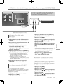
Operations
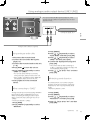
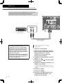
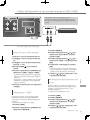
Using analogue audio output device (LINE1/LINE2)
(19)
Analogue audio cable (not supplied)
Blu-ray Disc player, etc.
Using analogue audio cable
1 Disconnect the AC mains lead.
2 Connect this unit and a Blu-ray Disc
player, etc.
3 Connect the AC mains lead to this unit.
( 15)
4 Press [AMP
] to turn this unit on.
5 Press [>INPUT<] repeatedly to select
“LINE1” or “LINE2”.
• You can also select the input source by
turning the input selector knob on the unit.
• Set to “LINE2” (see below) when “MAIN IN”
is displayed as input source of this unit.
6 Start playback on the connected
device.
When connecting to “LINE2”
Analogue audio input terminals (LINE2 IN/MAIN
IN) have both LINE2 and MAIN IN functions.
When connecting an analogue audio output
device, switch the input setting of this unit to
“LINE2”.
• The factory default is “LINE2”.
1 Press [AMP].
2 Press [>INPUT<] repeatedly to select
“MAIN IN”.
3 Press [MENU].
4 Press [
], [ ] repeatedly to select
“Input Mode” and then press [OK].
5 Press [
], [ ] repeatedly to select
“LINE2” and then press [OK].
6 Confirm the displayed message and
press [OK].
• The volume level set after switching to
“LINE2” is displayed. Confirm and adjust the
volume before pressing [OK].
7 Press [ ], [ ] to select “Yes” and then
press [OK].
Minimising sound distortion
If sound distortion occurs when using the
analogue audio input terminals, setting the
attenuator to “On” may improve the sound
quality.
• The factory default is “Off”.
1 Press [AMP].
2 Press [MENU].
3 Press [
], [ ] repeatedly to select
“Attenuator” and then press [OK].
4 Press [
], [ ] to select “On” and then
press [OK].
You can connect the Blu-ray Disc player, etc. with
analogue audio cable (not supplied) to this unit and
play back music.

20
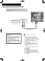
Operations
Using this unit as power amplifier
(20)
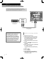
You can connect the AV receiver, control amplifier, etc. with
analogue audio cable (not supplied) to this unit and use this unit
as power amplifier.
AV receiver, control
amplifier, etc.
Set the volume of the AV receiver,
control amplifier, etc. to minimum before
connecting.
While using this unit as power amplifier,
the volume adjustment with this unit is
disabled. Adjust the volume little by little
with the connected device.
Do not input the audio signal from PRE
OUT/LINE OUT terminals to the MAIN IN
terminals of this unit. Doing so may cause
malfunction.
Analogue audio cable
(not supplied)
Using analogue audio cable
1 Disconnect the AC mains lead.
2 Connect this unit and AV receiver,
control amplifier, etc. after minimising
the volume of the device.
3 Connect the AC mains lead to this
unit. ( 15)
4 Press [AMP
] to turn this unit on.
5 Press [>INPUT<] repeatedly to select
“LINE2”.
• You can also select the input source by
turning the input selector knob on the unit.
6 Press [AMP].
7 Press [MENU].
8 Press [
], [ ] repeatedly to select
“Input Mode” and then press [OK].
9 Press [
], [ ] to select “MAIN IN” and
press [OK].
La page est en cours de chargement...
La page est en cours de chargement...
La page est en cours de chargement...
La page est en cours de chargement...
La page est en cours de chargement...
La page est en cours de chargement...
La page est en cours de chargement...
La page est en cours de chargement...
La page est en cours de chargement...
La page est en cours de chargement...
La page est en cours de chargement...
La page est en cours de chargement...
La page est en cours de chargement...
La page est en cours de chargement...
La page est en cours de chargement...
La page est en cours de chargement...
La page est en cours de chargement...
La page est en cours de chargement...
La page est en cours de chargement...
La page est en cours de chargement...
La page est en cours de chargement...
La page est en cours de chargement...
La page est en cours de chargement...
La page est en cours de chargement...
La page est en cours de chargement...
La page est en cours de chargement...
La page est en cours de chargement...
La page est en cours de chargement...
La page est en cours de chargement...
La page est en cours de chargement...
La page est en cours de chargement...
La page est en cours de chargement...
La page est en cours de chargement...
La page est en cours de chargement...
La page est en cours de chargement...
La page est en cours de chargement...
La page est en cours de chargement...
La page est en cours de chargement...
La page est en cours de chargement...
La page est en cours de chargement...
La page est en cours de chargement...
La page est en cours de chargement...
La page est en cours de chargement...
La page est en cours de chargement...
La page est en cours de chargement...
La page est en cours de chargement...
La page est en cours de chargement...
La page est en cours de chargement...
La page est en cours de chargement...
La page est en cours de chargement...
La page est en cours de chargement...
La page est en cours de chargement...
La page est en cours de chargement...
La page est en cours de chargement...
La page est en cours de chargement...
La page est en cours de chargement...
La page est en cours de chargement...
La page est en cours de chargement...
La page est en cours de chargement...
La page est en cours de chargement...
La page est en cours de chargement...
La page est en cours de chargement...
La page est en cours de chargement...
La page est en cours de chargement...
La page est en cours de chargement...
La page est en cours de chargement...
La page est en cours de chargement...
La page est en cours de chargement...
La page est en cours de chargement...
La page est en cours de chargement...
La page est en cours de chargement...
La page est en cours de chargement...
La page est en cours de chargement...
La page est en cours de chargement...
La page est en cours de chargement...
La page est en cours de chargement...
La page est en cours de chargement...
La page est en cours de chargement...
La page est en cours de chargement...
La page est en cours de chargement...
La page est en cours de chargement...
La page est en cours de chargement...
La page est en cours de chargement...
La page est en cours de chargement...
La page est en cours de chargement...
La page est en cours de chargement...
La page est en cours de chargement...
La page est en cours de chargement...
La page est en cours de chargement...
La page est en cours de chargement...
La page est en cours de chargement...
La page est en cours de chargement...
La page est en cours de chargement...
La page est en cours de chargement...
La page est en cours de chargement...
La page est en cours de chargement...
La page est en cours de chargement...
La page est en cours de chargement...
La page est en cours de chargement...
La page est en cours de chargement...
La page est en cours de chargement...
La page est en cours de chargement...
La page est en cours de chargement...
La page est en cours de chargement...
La page est en cours de chargement...
La page est en cours de chargement...
La page est en cours de chargement...
La page est en cours de chargement...
La page est en cours de chargement...
La page est en cours de chargement...
La page est en cours de chargement...
La page est en cours de chargement...
La page est en cours de chargement...
La page est en cours de chargement...
La page est en cours de chargement...
La page est en cours de chargement...
La page est en cours de chargement...
La page est en cours de chargement...
La page est en cours de chargement...
La page est en cours de chargement...
La page est en cours de chargement...
La page est en cours de chargement...
La page est en cours de chargement...
La page est en cours de chargement...
La page est en cours de chargement...
La page est en cours de chargement...
La page est en cours de chargement...
La page est en cours de chargement...
La page est en cours de chargement...
La page est en cours de chargement...
La page est en cours de chargement...
La page est en cours de chargement...
La page est en cours de chargement...
La page est en cours de chargement...
La page est en cours de chargement...
La page est en cours de chargement...
La page est en cours de chargement...
La page est en cours de chargement...
La page est en cours de chargement...
La page est en cours de chargement...
-
 1
1
-
 2
2
-
 3
3
-
 4
4
-
 5
5
-
 6
6
-
 7
7
-
 8
8
-
 9
9
-
 10
10
-
 11
11
-
 12
12
-
 13
13
-
 14
14
-
 15
15
-
 16
16
-
 17
17
-
 18
18
-
 19
19
-
 20
20
-
 21
21
-
 22
22
-
 23
23
-
 24
24
-
 25
25
-
 26
26
-
 27
27
-
 28
28
-
 29
29
-
 30
30
-
 31
31
-
 32
32
-
 33
33
-
 34
34
-
 35
35
-
 36
36
-
 37
37
-
 38
38
-
 39
39
-
 40
40
-
 41
41
-
 42
42
-
 43
43
-
 44
44
-
 45
45
-
 46
46
-
 47
47
-
 48
48
-
 49
49
-
 50
50
-
 51
51
-
 52
52
-
 53
53
-
 54
54
-
 55
55
-
 56
56
-
 57
57
-
 58
58
-
 59
59
-
 60
60
-
 61
61
-
 62
62
-
 63
63
-
 64
64
-
 65
65
-
 66
66
-
 67
67
-
 68
68
-
 69
69
-
 70
70
-
 71
71
-
 72
72
-
 73
73
-
 74
74
-
 75
75
-
 76
76
-
 77
77
-
 78
78
-
 79
79
-
 80
80
-
 81
81
-
 82
82
-
 83
83
-
 84
84
-
 85
85
-
 86
86
-
 87
87
-
 88
88
-
 89
89
-
 90
90
-
 91
91
-
 92
92
-
 93
93
-
 94
94
-
 95
95
-
 96
96
-
 97
97
-
 98
98
-
 99
99
-
 100
100
-
 101
101
-
 102
102
-
 103
103
-
 104
104
-
 105
105
-
 106
106
-
 107
107
-
 108
108
-
 109
109
-
 110
110
-
 111
111
-
 112
112
-
 113
113
-
 114
114
-
 115
115
-
 116
116
-
 117
117
-
 118
118
-
 119
119
-
 120
120
-
 121
121
-
 122
122
-
 123
123
-
 124
124
-
 125
125
-
 126
126
-
 127
127
-
 128
128
-
 129
129
-
 130
130
-
 131
131
-
 132
132
-
 133
133
-
 134
134
-
 135
135
-
 136
136
-
 137
137
-
 138
138
-
 139
139
-
 140
140
-
 141
141
-
 142
142
-
 143
143
-
 144
144
-
 145
145
-
 146
146
-
 147
147
-
 148
148
-
 149
149
-
 150
150
-
 151
151
-
 152
152
-
 153
153
-
 154
154
-
 155
155
-
 156
156
-
 157
157
-
 158
158
-
 159
159
-
 160
160


Technics SU-G700 Operating Instructions Manual
- Taper
- Operating Instructions Manual
dans d''autres langues
- italiano: Technics SU-G700
- English: Technics SU-G700
- Deutsch: Technics SU-G700
- Nederlands: Technics SU-G700
Documents connexes
-
Panasonic SUG700ES Le manuel du propriétaire
-
Panasonic SUR1000E Mode d'emploi
-
-
-
Technics SU-G30 Mode d'emploi
-
-
-
Panasonic SUC700EG Le manuel du propriétaire
Autres documents
-
-
-
Yamaha A-S2100BL Manuel utilisateur
-
Yamaha A-S2000 Le manuel du propriétaire
-
Pioneer A-70DA-S Manuel utilisateur
-
-
Panasonic SL-G700M2 Le manuel du propriétaire
-
Peachtree Audio nova65SE nova125SE nova220SE Manuel utilisateur
-
Lenco SB-100 Le manuel du propriétaire