Sherwood R-807 Operating Instructions Manual
- Catégorie
- Récepteurs AV
- Taper
- Operating Instructions Manual

R-807
Network AV receiVer
récepteur réseAu AV
receptor A/V coN coNexióN de red
operAtiNG iNstructioNs
Guide d’utiLisAtioN
iNstruccioNes de FuNcioNAMieNto

2
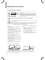
Safety Information
READ THIS BEFORE OPERATING YOUR UNIT
CAUTION
TO REDUCE THE RISK OF ELECTRIC SHOCK, DO NOT
REMOVE FRONT OR BACK COVER. NO USER-SERVICEABLE
PARTS INSIDE. REFER SERVICING TO QUALIFIED SERVICE
PERSONNEL.
CAUTION
RISK OF ELECTRIC SHOCK
DO NOT OPEN
This symbol indicates the presence of uninsulated “dangerous voltage” within the product’s enclosure
that may be of sufcient magnitude to constitute a risk of electric shock.
This symbol indicates important operating and maintenance (servicing) instructions in the literature
accompanying the appliance.
WARNING: TO REDUCE THE RISK OF FIRE OR ELECTRIC SHOCK, DO NOT EXPOSE THIS APPLIANCE TO
RAIN OR MOISTURE.
CAUTION
•
Leave space around the unit for sufcient ventilation.
•
Avoid installation in extremely hot or cold locations,
or in an area that is exposed to direct sunlight or
heating equipment.
•
Keep the unit free from moisture, water, and dust.
•
Do not let foreign objects in the unit.
•
Keep the ventilation openings clear of items, such as
newspapers, linens, or curtains.
•
Keep open ame from candles or other sources
away from the unit.
•
Observe the local regulations regarding disposal of
packaging materials, exhausted batteries and old
equipment.
•
Do not expose the unit to dripping or splashing, or
place objects lled with liquids such as vases.
•
Do not let insecticides, benzene, or thinner come in
contact with the unit.
•
Never disassemble or modify the unit in any way.
Notes on the AC power cord and the wall outlet
•
The unit remains connected to AC power as long as
it is plugged into the wall outlet, even if the unit has
been turned off.
•
To completely disconnect this product from AC
power, disconnect the plug from the wall socket
outlet.
•
When setting up this product, make sure that the AC
outlet you are using is easily accessible.
•
Disconnect the plug from the wall outlet when not
using the unit for long periods of time.
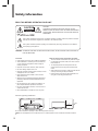
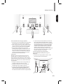
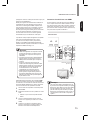
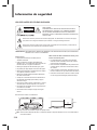
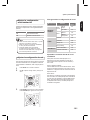
Caution regarding installation
Note
Wall
Do not block ventilation openings or stack other equipment on the top.
Note: For heat dispersal, do not install this unit in a conned space such as a bookcase or similar enclosure.

3
Safety Information
English
FCC Notice
This equipment has been tested and found to comply
with the limits for a Class B digital device, pursuant to
Part 15 of the FCC Rules. These limits are designed
to provide reasonable protection against harmful
interference in a residential installation. This equipment
generates, uses and can radiate radio frequency energy
and, if not installed and used in accordance with the
instructions, may cause harmful interference to radio
communications. However, there is no guarantee that
interference will not occur in a particular installation.
If this equipment does cause harmful interference to
radio or television reception, which can be determined
by turning the equipment off and on, the user is
encouraged to try to correct the interference by one or
more of the following measures:
Reorient or relocate the receiving antenna.
Increase the separation between the equipment and the
receiver.
Connect the equipment to an outlet on a circuit different
from that to which the receiver is connected.
Consult the dealer or an experienced radio/TV
technician for help.
This device complies with part 15 of the FCC Rules.
Operation is subject to the following two conditions:
(a) This device may not cause harmful interference,
and
(b) This device must accept any interference
received, including interference that may cause
undesired operation.
(FCC Part 15.21) Caution: changes or modications
not expressly approved by the party responsible for
compliance could void the user’s authority to operate
the equipment.
Important Safety Instructions
1 Read these instructions.
2 Keep these instructions.
3 Heed all warnings.
4 Follow all instructions.
5 Do not use this apparatus near water.
6 Clean only with dry cloth.
7 Do not block any ventilation openings. Install in
accordance with the manufacturer’s instructions.
8 Do not install near any heat sources such as
radiators, heat registers, stoves, or other apparatus
(including ampliers) that produce heat.
9 Do not defeat the safety purpose of the polarized
or grounding-type plug. A polarized plug has two
blades with one wider than the other. A grounding
type plug has two blades and a third grounding
prong. The wide blade or the third prong are
provided for your safety. If the provided plug does
not t into your outlet, consult an electrician for
replacement of the obsolete outlet.
10 Protect the power cord from being walked on
or pinched particularly at plugs, convenience
receptacles, and the point where they exit from the
apparatus.
11 Only use attachments/accessories specied by the
manufacturer.
12 Use only with the cart, stand, tripod,
bracket, or table specied by the
manufacturer, or sold with the
apparatus. When a cart is used,
use caution when moving the cart/
apparatus combination to avoid injury
from tip-over.
13 Unplug this apparatus during lightning storms or
when unused for long periods of time.
14 Refer all servicing to qualied service personnel.
Servicing is required when the apparatus has been
damaged in any way, such as power-supply cord or
plug is damaged, liquid has been spilled or objects
have fallen into the apparatus, the apparatus has
been exposed to rain or moisture, does not operate
normally, or has been dropped.

4
Table of Contents
2 SAFETY INFORMATION
6 GETTING STARTED
6 What's Included
7 Installing the Remote Control Battery
7 Operating the range of the Remote Control
8 PARTS DESCRIPTION
8 Front Panel
9 Front Display
9 Rear Panel
10 Remote Control
11 MAKING CONNECTIONS
11 Connection Overview
12 Connecting Speakers
12 Placing Speakers
14 Connecting Speakers
15 Setting the Speaker
16 Connecting a TV
16 Connecting with an HDMI TV
17 Connecting with a non-HDMI TV
18 Connecting Playback Components
18 Connecting HDMI Components
18 Connecting Video Components
19 Connecting Audio Components
21 Connecting Recording Components
21 Connecting to a Network
22 Connecting an Antenna
22 Connecting FM Antenna
23 Connecting AM Antenna
24 Connecting to Muti-Room
25 Connecting to the System's Internal Amplier
25 Connecting to an External Amplier
26 Controlling Room2
26 Connecting Power
27 OPERATING YOUR SYSTEM
27 Listening to Your System
27 Basic Operation
27 Muting the Sound
28 Enjoying Surround Effects
28 Setting the Surround Mode
31 Cancelling the Surround Mode for Stereo
Operation
31 Adjusting the Current Channel Level
32 Listening to Music on USB
32 To Stop Playback
32 To Pause Playback
32 To Skip Forward or Backward
33 To Play Repeatedly
33 To Play Randomly
33 Listening to Internet Radio
34 Listening to Music from the Media Server
34 Conguring the Windows Media Player
35 Listening to Music from the Media Server
35 Using the Sherwood Remote Application
35 Preparing for the Application
36 Using the Application
40 Listening to FM Radio
40 Auto Tuning
40 Manual Tuning
40 Manual Presetting
41 Auto Presetting
41 Tuning in to Preset Stations
41 Recording

Table of Contents
5
English
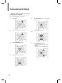
42 CUSTOMIZING SETTINGS
42 Setting the System
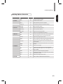
43 Setting Options Overview
44 Setting the System Setup
44 AMP Assign
44 Automatic Power Control
44 Network Standby Control
44 Setting the Speaker Setup
44 Auto Setup
46 Speaker Setup
46 Speaker Crossover
46 Speaker Distance
46 Speaker Channel Level
47 Setting the HDMI Setup
47 HDMI
47 CEC Control
47 Setting the Surround Parameter Setup
47 Height Gain
47 PANORAMA
47 Center Width
47 Dimension
47 Center Image
48 DRC
48 Tone
48 Sound Delay
48 Low Frequency Effect
49 Setting the Multi Room Setup
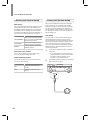
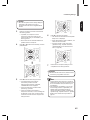
49 Setting the Network Setup
49 Network Settings Overview
49 Setting the Direct Wireless Network
Connection
50 Setting the Wired Network Connection
50 Setting Other Network Options
50 Viewing the Network Information
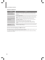
51 TROUBLESHOOTING
51 GENERAL
51 SOUND
52 VIDEO
53 USB device
54 NETWORK CONNECTION
54 Important Information Regarding the HDMI
Connection
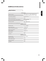
55 ADDITIONAL INFORMATION
55 Specications
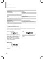
56 Trademarks and Licenses
56 DTS-HD Master Audio
56 Dolby TrueHD
56 HDMI

6
Getting Started
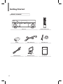
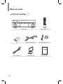
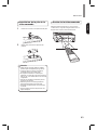
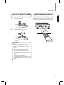
What's Included
Main unit Remote control (1 ea)
Battery Power Cable (1 ea) Setup Mic (1 ea)
R807
NETWORK AV RECEIVER
OPERATING INSTRUCTIONS
FM antenna (1 ea) AM Antenna (1 ea) User Manual

7
Getting Started
English
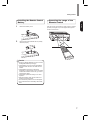
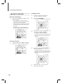
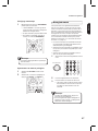
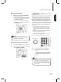
Installing the Remote Control
Battery
1
Remove the battery cover.
2
Insert two AAA size batteries with the polarity
matched properly.
•
Always use alkaline batteries, and do not use the
rechargeable batteries (Ni-Cd type).
•
If the batteries run out, remove the old batteries
and replace them with new ones within several
minutes.
•
If the batteries are removed or have been
exhausted for a longer period of time, memorized
contents will be cleared. In this case, you should
memorize them again.
•
If the battery is placed incorrectly, it can cause
explosion.
•
Remove the battery if the remote control is not
used for a long period of time.
•
Do not leave the product in a hot or humid place.
•
Do not handle and store the battery with metallic
tools.
Caution
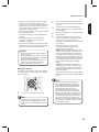
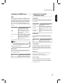
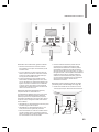
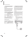
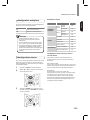
Operating the range of the
Remote Control
Use the remote control within a range of about 7 meters
(23 feet) and angles of up to 30 degrees aiming at the
remote control sensor.

8
Parts Description
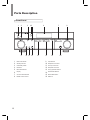
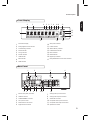
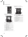
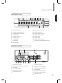
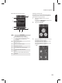
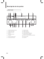
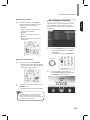
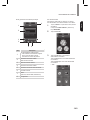
Front Panel
9 10 11 12 15 16
1 2 3 54 6 7 8
13 14
1
Main Power Switch
2
Standby Indicator
3
On/Standby Switch
4
IR Sensor
5
Band Select Button
6
Display
7
Surround Select Buttons
8
Master Volume Control
9
Input Selector
10
Headphone Connector
11
Aux Input Connector
12
Setup MIC Connector
13
Tuning Up/Down Buttons
14
Preset Select Buttons
15
Stereo Mode Button
16
USB Port

Parts Description
9
English
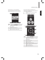
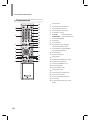
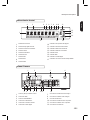
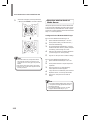
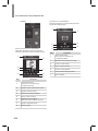
Front Display
1
14
13
12
17 1516
432 5 6 7 8 9 10 11
1
Information Display
2
Dolby Digital Surround indicator
3
Auto Detecting Indicator
4
Stereo Indicator
5
Tuning indicator
6
Room2 Indicator
7
USB Indicator
8
MP3 Indicator
9
WMA Indicator
10
Sleep Timer Indicator
11
Preset Indicator
12
Station Memory Indicator
13
Preset Station Indicator
14
Direct Indicator
15
HDMI Indicator
16
Digital Input Indicator
17
Dolby/DTS/DSP Surround mode indicators
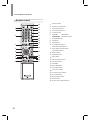
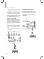
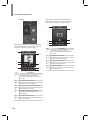
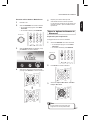
Rear Panel
5 6 7 8 9 10 11 12
1 2 3 4
1
Monitor OUT (ARC) Connector
2
HDMI Connectors
3
LAN/ETHERNET Connector
4
AC Input Connector
5
Radio Antenna Connectors
6
Digital Audio Connectors
7
Analog Audio Input Connectors
8
Analog Audio Output Connectors
9
Subwoofer Connector
10
Composite Video Input Connectors
11
Composite Video Output Connectors
12
Speaker Connectors

R-807 NETWORK AV RECEIVER
10
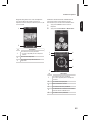
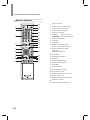
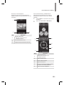
Remote Control
1
Power On Button
2
Room2 Input Select Button
3
Source Select Buttons
4
Surround Select Buttons
5
Top Menu Button
6
▲/▼/◄/► Select Buttons
ENTER/MEMO Enter/Memory Button
7
Display/Mode Button
8
Stop Button
9
Repeat Button
10
Tuning Up/Down Buttons
Rewind/Fast forward Buttons
11
Preset Station Up/Down Buttons
Previous/Next Buttons
12
Random Button
13
Play/Pause Button
14
Return Button
15
Volume Up/Down Buttons
16
Setup Menu Button
17
Mute Button
18
Stereo Mode Button
19
Audio Assign Button
20
Channel Level Button
21
Test Tone Sequence Button
22
Tone Control Button
23
Room2 ON/OFF Button
24
Standby Button
25
Room2 Volume Up/Down Buttons
1
2
5
7
6
9
10
8
3
4
18
16
24
25
23
17
12
22
21
20
19
15
11
14
13

11
English
Making Connections
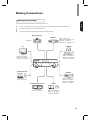
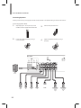
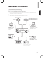
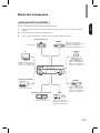
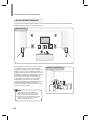
Connection Overview
Connect various external devices to the ports on the main unit.
1
Find an external device you want to connect to the main unit as shown on the following illustration.
2
Check the connection type of the external device.
3
Go to the appropriate illustration and check the connection details.
HDMI IN - See page 16.
VIDEO OUT - See page 17.
DIGITAL IN - See page 19.
TV
BD/BDR
Speaker System
DVD/DVR
STB/CBL
GAME
Audio External Devices
Portable Devices
HDMI IN - See page 16.
VIDEO IN/OUT - See page 18, 21.
DIGITAL IN - See page 19.
AUDIO IN/OUT - See page 20, 21.
See page 12.
HDMI IN - See page 16.
VIDEO IN - See page 18.
DIGITAL IN - See page 19.
AUDIO IN - See page 20.
HDMI IN - See page 16.
VIDEO IN - See page 18.
DIGITAL IN - See page 19.
AUDIO IN - See page 20.
HDMI IN - See page 16.
DIGITAL IN - See page 19.
AUDIO IN - See page 20.
AUDIO IN - See page 20.
F.AUX - See page 20.

12
R-807 NETWORK AV RECEIVER
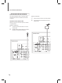
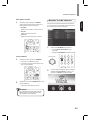
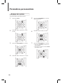
Connecting Speakers
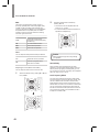
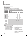
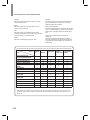
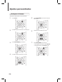
Placing Speakers
Determine the locations for your speaker placement according to their manufacturer’s directions and the layout of
your listening room. Use the illustration on page 13 as a guide for speaker placement.
To create the most realistic surround-sound environment possible, you should place your speakers in a circle around
the listener. You should angle each speaker so it directly faces the listening position. Use the diagram below as a
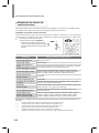
guide.
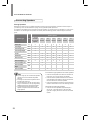
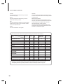
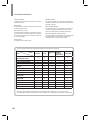
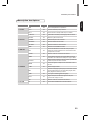
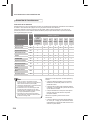
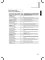
Speaker Type Abbr.
Speaker System
7.1 Channel
(for Dolby
Pro Logic IIz
playback)
7.1
Channel
6.1
Channel
5.1
Channel
4.1
Channel
3.1
Channel
2.1
Channel
Front Left FL ● ● ● ● ● ● ●
Front Right FR ● ● ● ● ● ● ●
Front Height Left FHL ●
Front Height Right FHR ●
Center C ● ● ● ● ●
Subwoofer SW ● ● ● ● ● ● ●
Surround Left SL ● ● ● ● ●
Surround Right SR ● ● ● ● ●
Surround Back Left SBL ●
Surround Back
Right
SBR ●
Surround Back SB ●
•
If you’re using only one surround back speaker,
connect it to the surround back left speaker
terminals.
•
Front high and surround back speakers cannot
be used at the same time.
•
To avoid interference with the TV picture when
using a conventional TV, use only magnetically
shielded front left, right, and center speakers.
•
To obtain the best surround effects, all the
speakers except the subwoofer should be full
range speakers.
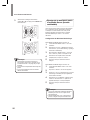
Note
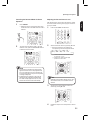
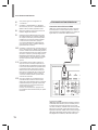
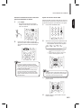
Front left and right speakers and center speaker
•
Place the front speakers with their front surfaces as
ush to the TV or monitor screen as possible.
•
Place the center speaker between the front left and
right speakers and its distance should not be further
from the listener than the front speakers.
•
Place each speaker so that sound is aimed at where
listener's ears would be in the main listening position.
Surround left and right speakers
•
Place the surround speakers approximately 60 ~
90 cm (24 ~ 36 inches) above on the direct left/
right side or slightly behind the ear level of a seated
listener.

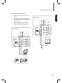
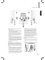
13
Making Connections
English
TV
C
FHL
FL
SW
SL
SBL SBR
SB
SR
FR
FHR
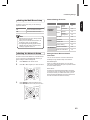
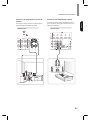
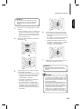
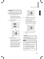
Surround back left and right speakers
•
Place the surround back speakers at the back facing
forward together and closer than front speakers.
•
When using a single surround back speaker, place it
at the rear center facing forward at a slightly higher
position (0 to 20 cm) than the surround speakers.
•
We recommend installing the surround back
speaker(s) facing slightly. This effectively prevents
the surround back channel signals from bouncing
off the TV or screen at the front center, resulting in
interference and making the sense of movement
from the front to the back less sharp.
Subwoofer
Because a room’s shape and volume can have a
dramatic effect on a subwoofer’s performance, you
should experiment with placement in order to nd the
location that produces the best results in your particular
listening room. With that in mind, these rules will help
you get started.
•
Placing the subwoofer next to a wall generally will
increase the amount of bass in the room.
•
Placing the subwoofer in a corner generally will
maximize the amount of bass in the room.
•
In many rooms, placing the subwoofer along the
same plane as the left and right speakers can
produce the best integration between the sound of
the subwoofer and that of the left and right speakers.
•
In some rooms, the best performance comes from
placing the subwoofer behind the listener. A good
way to determine the best location for the subwoofer
is by temporarily placing it in the listening position
and playing music with strong bass content. Move
around to various locations in the room while the
system is playing (putting your ears where the
subwoofer would be placed), and listen until you nd
the location where the bass performance is best.
Place the subwoofer in that location.
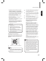
Front height left and right speakers
(Recommended for Dolby Pro Logic IIz
playback)
•
Place the front height speakers at least 1 meter
(40 inches) above the front speakers.
Front height
speaker
Front
speaker
At least 1 m
Surround
speaker
Surround back
speaker
60 ~ 90 cm

14
R-807 NETWORK AV RECEIVER
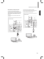
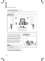
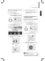
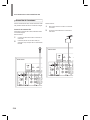
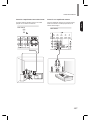
Connecting Speakers
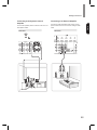
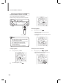
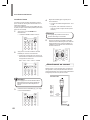
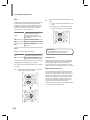
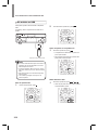
Carefully check the left (L) and right (R) channels and the polarities on the speakers being connected to this receiver.
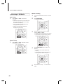
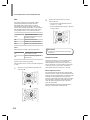
3
Insert the bare part of the wire.
4
Tighten the speaker terminal by turning it
clockwise.
Sub
Woofer
Front
Right
Front
Left
CenterSurround
Right
Surround
Left
Surround Back
/Front Height
/Room2
Left
Surround Back
/Front Height
/Room2
Right
Rear Panel
Sub
Woofer
Font
Right
Font
Left
Surround
Right
Surround
Left
Center
Surround Back/
Front Height/
Room2
Right
Surround Back/
Front Height/
Room2
Left
Connecting Speaker Wires
1
Strip away approx. 10 mm (3/8 inch) of wire
insulation, and then tightly twist the wire ends.
2
Loosen the speaker terminal by turning it
counter-clockwise.

15
Making Connections
English
•
Be sure to connect speakers rmly and accurately
according to the channel (left and right) and the
polarity (+ and −). If the connections are incorrect, no
sound will be produced by the speakers, and if the
polarity of the speaker connection is incorrect, the
sound will be unnatural and tinny.
•
When listening in Dolby Pro Logic IIz mode, connect
the front height speakers.
•
To install the speakers, see “Placing Speakers” on
page 12.
•
For ROOM 2 playback, connect the ROOM
2 speakers. For details, see “Connecting to
Multi-Room” on page 24.
•
After installing the speakers, rst adjust the speaker
settings according to your environment and speaker
layout. For details, see “Setting the Speaker”.
•
Be sure to use the speakers with the impedance
of 6 ohms or above.
•
Do not let bare speaker wires touch each other or
any metal part of this receiver. This could damage
the main unit and/or the speakers.
•
Never touch the speaker terminals while the AC
input cord is connected to the wall AC outlet.
Doing so could result in electric shock.
Caution
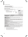
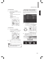
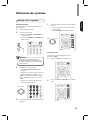
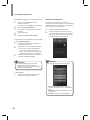
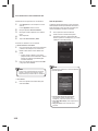
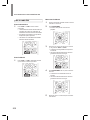
Setting the Speaker
You will be using the following remote control buttons
to congure the main unit. For details on the speaker
setup, see page 44.
1
Turn on your TV and select the TV input.
•
Although you can congure the main unit using
only its front-panel message display, it is much
easier to use the On-Screen Display (OSD) menu
system.
Note
2
Press the remote control’s SETUP button. The
main unit’s OSD System Setup menu will appear
on the TV.
3
Use the remote’s arrow and ENTER buttons
to select “Speaker Setup”. The Speaker Setup
menu will appear.
4
Select “Speaker Settings”. The Speaker Settings
menu will appear.
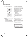
5
Use the remote’s left and right arrow buttons
to select OFF, SMALL or LARGE for the Front,
Center and Surround speaker positions,
depending on the speakers you have connected
to the receiver.
OFF: Select this setting if you have not
connected a speaker in that position (not
available for the front speakers).
SMALL: Select this setting if the speaker is not
capable of producing clean, deep bass energy
at output levels that match those produced by
a powered subwoofer. All bass in that channel
is removed from that speaker and is sent to the
subwoofer (or to the front speakers if subwoofer
is set to NO). Most speakers (unless they are
large and powerful) should be considered
SMALL.
LARGE: Select this setting if the speaker is
capable of producing clean, deep bass energy
at output levels that match those produced by a
powered subwoofer. All bass in that channel is
sent to that speaker.
When you’re nished, press the remote control’s
RETURN button to return to the Speaker Setting
menu.
•
If your system has a subwoofer and you set
the front speakers to LARGE, the subwoofer
may only play Dolby Digital-audio signals and
DTS-encoded program material that contains
LFE channel information. If you set your
front speakers to LARGE and you want your
subwoofer to reproduce bass from all program
material, set the Subwoofer to PLUS (see below).
•
For subwoofer, select YES (if your system has
a subwoofer), NO (if your system does not have
a subwoofer), or PLUS (if your system has a
subwoofer, you set your front speakers to LARGE
and you want your subwoofer to reproduce bass
from all program material).
Note

16
R-807 NETWORK AV RECEIVER
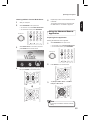
6
You can skip the “Crossover” setting.
7
Select “Speaker Distance”. The Speaker
Distance menu will appear.
8
Measure the distance from each speaker in your
system to the listener. Set the distances.
9
Use the remote’s left and right arrow buttons to
change the distance setting for each speaker
so that it matches the distance you wrote down
in step 8. When you’re nished, press the
remote control’s RETURN button to return to the
Speaker Setting menu.
10
Select “Channel Level”. The Channel Level
menu will appear. Use the remote’s left and
right arrow buttons to set Test Tone to “Manual”
and press the remote’s ENTER button. After the
on-screen countdown you will hear test noise
through the front left speaker.
11
Sit in the main listening position and adjust the
main unit’s volume control so the test sound
is moderately loud. Note the volume of the
test sound through the rst speaker. Press the
remote’s down arrow button to advance the
test noise to each of your system’s speakers
and note the volume level of the noise in each
speaker.
12
As you advance the test sound through the
speakers, use the remote’s left and right arrow
buttons to adjust the volumes of the channels
until all of them play at the same volume.
When you’re nished, press the remote’s SETUP
button to turn off the on-screen menus.
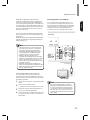
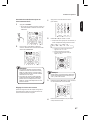
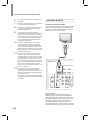
Connecting a TV
Connecting with an HDMI TV
With HDMI, you can easily enjoy high quality sounds
and images. The main unit plays audio from HDMI
compatible products while also passing on the video
signal to a HDMI-connected TV.
Rear Panel
About HDMI
HDMI (High Denition Multimedia Interface) supports
both audio and video on a single digital connection
for use with DVD players, DTV, set-top boxes, and
other AV devices. HDMI was developed to provide
the technologies of High Bandwidth Digital Content
Protection (HDCP) as well as Digital Visual Interface
(DVI) in one specication. HDCP is used to protect
the digital content transmitted and received by
DVI-compliant displays.

17
Making Connections
English
HDMI has the capability to support standard,
enhanced, or high-denition video plus standard to
multi-channel surround-sound audio. HDMI features
include uncompressed digital video, a bandwidth of up
to 2.2 gigabytes per second (with HDTV signals), one
connector (instead of several cables and connectors),
and communication between the AV source and AV
devices such as DTVs.
This main unit is also compatible with the DeepColor
and x.v.Color feature (x.v.Color is trademarks of Sony
Corporation).
HDMI, the HDMI logo and High-Denition Multimedia
Interface are trademarks or registered trademarks of
HDMI Licensing, LLC.
•
Check the setup of the connected component
if an image is poor or there is no sound from a
component connected via the HDMI cable.
•
Audio signals (sampling frequency, bit length,
etc.) transmitted from an HDMI jack may be
suppressed by the connected component.
•
When the connected component is not
compatible with copyright protection technology
(HDCP), the image and the sound from the HDMI
TV OUT jack may be distorted or may be not
output. In this case, check the specication of the
connected component.
•
Regardless of which input is selected for the
system, the video signal from the HDMI input jack
(BD, DVD, SAT) that was last selected is output
from the HDMI TV OUT jack.
Note
ConrmingtheHDMIcontrolfunctions
To use the HDMI control functions properly, it is
recommended to conrm the HDMI control functions
usable with each connected component by performing
the following operations.
1
Turn on all the components connected with HDMI
cables.
2
Turn the TV off to standby mode.
•
Conrm that all the components are turned off.
3
With all the components off, start playback of a
device (connected with HDMI cable).
4
Conrm that all the components are turned on and
the inputs of the main unit and TV are switched
automatically.
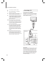
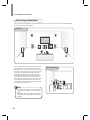
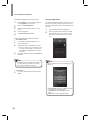
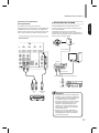
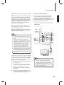
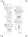
Connecting with a non-HDMI TV
If your TV does not have an HDMI connector, or if
your TV does have an HDMI connector but you are
connecting some source devices with only composite
video connectors, use a composite video cable (not
included) to connect the composite Monitor Out
connector to your TV’s composite video connector.
Composite
VIDEO IN
Composite Video Cable
(not supplied)
TV
Rear Panel
•
The on-screen display (OSD) only appears
through the Composite Monitor Out connector.
If you want to use the main unit's OSD menus
you will need to connect its Composite Monitor
Out connector to your TV even if you are not
connecting any composite video source devices
to the system.
Note

18
R-807 NETWORK AV RECEIVER
Connecting Playback
Components
Source devices are components from which a playback
signal originates, e.g., a Blu-ray Disc™ or DVD player;
a set-top box, or HDTV tuner, etc. The receiver has
several different types of input connectors for your
audio and video source devices: HDMI, composite
video, optical digital audio, coaxial digital audio and
analog audio.
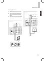
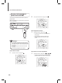
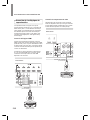
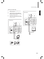
Connecting HDMI Components
If any of your source devices have HDMI connectors,
using those connectors will provide the best possible
video and audio performance quality. Since the HDMI
cable carries both digital video and digital audio
signals, you do not have to make any additional audio
connections for devices you connect via HDMI cables.
If you have an HDMI or DVI (with HDCP) equipped
component (Blu-ray disc player, etc.), you can connect
it to this receiver using a commercially available HDMI
cable.
HDMI Cable
(not supplied)
HDMI-Equipped Source
Device
Rear Panel
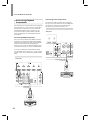
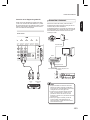
Connecting Video Components
You will need to make composite video connections
from your source devices that do not have HDMI video
connections. You will also need to make an audio
connection from the device to the main unit.
Composite
VIDEO OUT
Composite Video Cable
(not supplied)
Composite Video-Equipped
Source Device
Rear Panel

19
Making Connections
English
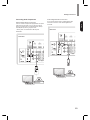
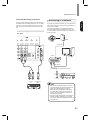
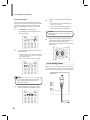
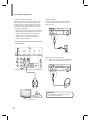
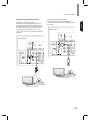
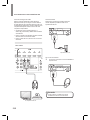
Connecting Audio Components
Optical Digital Audio Connection
You can connect components equipped with an optical
output jack. On the main unit, you can enjoy the full
sound of components, such as DVD players, set-top
box, BD (Blu-ray Disc™) players or TVs.
* “Blu-ray Disc” is a trademark of Blu-ray Disc
Association.
OPTICAL
OUT
TV, DVD Player, etc.
Rear Panel
Coaxial Digital Audio Connection
If your source devices have a coaxial digital output,
connect it to the main unit's coaxial digital audio
connector.
OUT
TV, DVD Player, etc.
Rear Panel
OUT

20
R-807 NETWORK AV RECEIVER
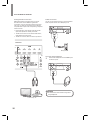
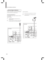
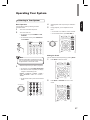
Analogue Audio Connection
Make analog audio connections from your source
devices that do not have HDMI or digital audio
connections. If you’re connecting video sources to the
main unit, you must also connect the source device’s
composite video output to the corresponding composite
video connector.
•
Ensure the left (L) and right (R) channels and the
inputs and outputs are correctly connected.
•
To listen to the sound of a connected audio device,
select AUX as the input source.
•
To listen to TV audio, select TV as the input source.
RL
TV, DVD Player, etc.
Rear Panel
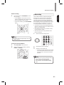
F.AUX Connection
You can use the F.AUX input jack to connect portable
audio components such as an MP3 player, etc.
MP3 player, etc.
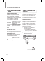
Listening with Headphones
1
Connect the headphones to the PHONES jack
on the front panel.
•
Be careful not to set the volume too high when
using headphones.
Caution
La page est en cours de chargement...
La page est en cours de chargement...
La page est en cours de chargement...
La page est en cours de chargement...
La page est en cours de chargement...
La page est en cours de chargement...
La page est en cours de chargement...
La page est en cours de chargement...
La page est en cours de chargement...
La page est en cours de chargement...
La page est en cours de chargement...
La page est en cours de chargement...
La page est en cours de chargement...
La page est en cours de chargement...
La page est en cours de chargement...
La page est en cours de chargement...
La page est en cours de chargement...
La page est en cours de chargement...
La page est en cours de chargement...
La page est en cours de chargement...
La page est en cours de chargement...
La page est en cours de chargement...
La page est en cours de chargement...
La page est en cours de chargement...
La page est en cours de chargement...
La page est en cours de chargement...
La page est en cours de chargement...
La page est en cours de chargement...
La page est en cours de chargement...
La page est en cours de chargement...
La page est en cours de chargement...
La page est en cours de chargement...
La page est en cours de chargement...
La page est en cours de chargement...
La page est en cours de chargement...
La page est en cours de chargement...
La page est en cours de chargement...
La page est en cours de chargement...
La page est en cours de chargement...
La page est en cours de chargement...
La page est en cours de chargement...
La page est en cours de chargement...
La page est en cours de chargement...
La page est en cours de chargement...
La page est en cours de chargement...
La page est en cours de chargement...
La page est en cours de chargement...
La page est en cours de chargement...
La page est en cours de chargement...
La page est en cours de chargement...
La page est en cours de chargement...
La page est en cours de chargement...
La page est en cours de chargement...
La page est en cours de chargement...
La page est en cours de chargement...
La page est en cours de chargement...
La page est en cours de chargement...
La page est en cours de chargement...
La page est en cours de chargement...
La page est en cours de chargement...
La page est en cours de chargement...
La page est en cours de chargement...
La page est en cours de chargement...
La page est en cours de chargement...
La page est en cours de chargement...
La page est en cours de chargement...
La page est en cours de chargement...
La page est en cours de chargement...
La page est en cours de chargement...
La page est en cours de chargement...
La page est en cours de chargement...
La page est en cours de chargement...
La page est en cours de chargement...
La page est en cours de chargement...
La page est en cours de chargement...
La page est en cours de chargement...
La page est en cours de chargement...
La page est en cours de chargement...
La page est en cours de chargement...
La page est en cours de chargement...
La page est en cours de chargement...
La page est en cours de chargement...
La page est en cours de chargement...
La page est en cours de chargement...
La page est en cours de chargement...
La page est en cours de chargement...
La page est en cours de chargement...
La page est en cours de chargement...
La page est en cours de chargement...
La page est en cours de chargement...
La page est en cours de chargement...
La page est en cours de chargement...
La page est en cours de chargement...
La page est en cours de chargement...
La page est en cours de chargement...
La page est en cours de chargement...
La page est en cours de chargement...
La page est en cours de chargement...
La page est en cours de chargement...
La page est en cours de chargement...
La page est en cours de chargement...
La page est en cours de chargement...
La page est en cours de chargement...
La page est en cours de chargement...
La page est en cours de chargement...
La page est en cours de chargement...
La page est en cours de chargement...
La page est en cours de chargement...
La page est en cours de chargement...
La page est en cours de chargement...
La page est en cours de chargement...
La page est en cours de chargement...
La page est en cours de chargement...
La page est en cours de chargement...
La page est en cours de chargement...
La page est en cours de chargement...
La page est en cours de chargement...
La page est en cours de chargement...
La page est en cours de chargement...
La page est en cours de chargement...
La page est en cours de chargement...
La page est en cours de chargement...
La page est en cours de chargement...
La page est en cours de chargement...
La page est en cours de chargement...
La page est en cours de chargement...
La page est en cours de chargement...
La page est en cours de chargement...
La page est en cours de chargement...
La page est en cours de chargement...
La page est en cours de chargement...
La page est en cours de chargement...
La page est en cours de chargement...
La page est en cours de chargement...
La page est en cours de chargement...
La page est en cours de chargement...
La page est en cours de chargement...
La page est en cours de chargement...
La page est en cours de chargement...
La page est en cours de chargement...
La page est en cours de chargement...
La page est en cours de chargement...
La page est en cours de chargement...
La page est en cours de chargement...
La page est en cours de chargement...
La page est en cours de chargement...
La page est en cours de chargement...
La page est en cours de chargement...
La page est en cours de chargement...
La page est en cours de chargement...
La page est en cours de chargement...
La page est en cours de chargement...
-
 1
1
-
 2
2
-
 3
3
-
 4
4
-
 5
5
-
 6
6
-
 7
7
-
 8
8
-
 9
9
-
 10
10
-
 11
11
-
 12
12
-
 13
13
-
 14
14
-
 15
15
-
 16
16
-
 17
17
-
 18
18
-
 19
19
-
 20
20
-
 21
21
-
 22
22
-
 23
23
-
 24
24
-
 25
25
-
 26
26
-
 27
27
-
 28
28
-
 29
29
-
 30
30
-
 31
31
-
 32
32
-
 33
33
-
 34
34
-
 35
35
-
 36
36
-
 37
37
-
 38
38
-
 39
39
-
 40
40
-
 41
41
-
 42
42
-
 43
43
-
 44
44
-
 45
45
-
 46
46
-
 47
47
-
 48
48
-
 49
49
-
 50
50
-
 51
51
-
 52
52
-
 53
53
-
 54
54
-
 55
55
-
 56
56
-
 57
57
-
 58
58
-
 59
59
-
 60
60
-
 61
61
-
 62
62
-
 63
63
-
 64
64
-
 65
65
-
 66
66
-
 67
67
-
 68
68
-
 69
69
-
 70
70
-
 71
71
-
 72
72
-
 73
73
-
 74
74
-
 75
75
-
 76
76
-
 77
77
-
 78
78
-
 79
79
-
 80
80
-
 81
81
-
 82
82
-
 83
83
-
 84
84
-
 85
85
-
 86
86
-
 87
87
-
 88
88
-
 89
89
-
 90
90
-
 91
91
-
 92
92
-
 93
93
-
 94
94
-
 95
95
-
 96
96
-
 97
97
-
 98
98
-
 99
99
-
 100
100
-
 101
101
-
 102
102
-
 103
103
-
 104
104
-
 105
105
-
 106
106
-
 107
107
-
 108
108
-
 109
109
-
 110
110
-
 111
111
-
 112
112
-
 113
113
-
 114
114
-
 115
115
-
 116
116
-
 117
117
-
 118
118
-
 119
119
-
 120
120
-
 121
121
-
 122
122
-
 123
123
-
 124
124
-
 125
125
-
 126
126
-
 127
127
-
 128
128
-
 129
129
-
 130
130
-
 131
131
-
 132
132
-
 133
133
-
 134
134
-
 135
135
-
 136
136
-
 137
137
-
 138
138
-
 139
139
-
 140
140
-
 141
141
-
 142
142
-
 143
143
-
 144
144
-
 145
145
-
 146
146
-
 147
147
-
 148
148
-
 149
149
-
 150
150
-
 151
151
-
 152
152
-
 153
153
-
 154
154
-
 155
155
-
 156
156
-
 157
157
-
 158
158
-
 159
159
-
 160
160
-
 161
161
-
 162
162
-
 163
163
-
 164
164
-
 165
165
-
 166
166
-
 167
167
-
 168
168
-
 169
169
-
 170
170
-
 171
171
-
 172
172


Sherwood R-807 Operating Instructions Manual
- Catégorie
- Récepteurs AV
- Taper
- Operating Instructions Manual
dans d''autres langues
- English: Sherwood R-807
- español: Sherwood R-807
Documents connexes
Autres documents
-
Harman 2600 Manuel utilisateur
-
ONKYO HT-R791 Le manuel du propriétaire
-
Yamaha RX V3900 - AV Network Receiver Manuel utilisateur
-
Yamaha RX-Z7 Le manuel du propriétaire
-
Harman Kardon AVR 171S Le manuel du propriétaire
-
Sony STR-DA3300ES Mode d'emploi
-
Yamaha DSP-Z11 Le manuel du propriétaire
-