
Need help? Visit Sauder.com to view video assembly tips or chat with a live rep.
Prefer the phone? Call 1-800-523-3987.
Share your journey!
sauder.com
Knick-knack
paddywhack,
give your stu a home.
NOTE: THIS INSTRUCTION
BOOKLET CONTAINS IMPORTANT
SAFETY INFORMATION.
PLEASE READ AND KEEP FOR
FUTURE REFERENCE.
English pg 1-19
Français pg 20-22
Español pg 23-25
Lot # 376718 10/09/15
Purchased: __________________
Be sure to give us a ring before
making any returns. 1-800-523-3987
Hutch
Via Collection | Model 419717

Table of Contents Assembly Tools Required
Part Identifi cation
Hardware Identifi cation
Assembly Steps
Français
Español
Safety
Warranty
Hammer
Not actual size
No. 2 Phillips Screwdriver
Tip Shown Actual Size
3
4
5-19
20-22
23-25
26
27
419717 www.sauder.com/servicesPage 2
Electric drill with 1/4" bit
(ONLY in indicated step)

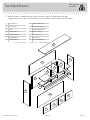
Part Identifi cation
å While not all parts are labeled, some of the parts will have a label or an inked letter on the edge
to help distinguish similar parts from each other. Use this part identifi cation to help identify similar parts.
Now you know
our ABCs.
A RIGHT END (1)
B LEFT END (1)
C TOP (1)
D UPPER SHELF (1)
E LOWER SHELF (1)
F UPPER BACK (1)
G LOWER BACK (1)
H LARGE UPRIGHT (2)
I SMALL UPRIGHT (3)
J CENTER UPRIGHT (1)
K RIGHT DOOR (2)
L LEFT DOOR (2)
M VALANCE (1)
N BULLETIN BOARD (1)
A
B
C
D
E
F
G
H
H
J
K
K
L
L
M
N
I
419717www.sauder.com/services
Page 3

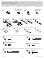
Hardware Identifi cation
å Screws are shown actual size. You may receive extra hardware with your unit.
FELT DISC CARD - 1
1M
GOLD 1" MACHINE SCREW - 8
50S
BLACK 9/16" LARGE HEAD SCREW - 10
1S
ANGLE BRACKET - 5
5G
BROWN 7/16" LARGE HEAD SCREW - 8
6S
BLACK 1-7/8" FLAT HEAD SCREW - 15
2S
BLACK 2-1/4" FLAT HEAD SCREW - 4
26S
TOUCH-UP PEN - 1
10M
7F
TWIST-LOCK
®
FASTENER - 14
13F
MINI TWIST-LOCK
®
FASTENER - 16
61P
TWIST-LOCK
®
FASTENER COVER - 14
62P
MINI TWIST-LOCK
®
COVER - 12
METAL PIN - 10
1R
PULL - 4
12K
BLACK 1/2" FLAT HEAD SCREW - 16
11S
HINGE - 4
53H
419717 www.sauder.com/servicesPage 4
CORD COVER - 4
66P
BULLETIN BOARD
BRACKET - 8
63G
RAISED HINGE - 4
31H
Raised
area

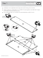
Step 1
Look for this icon. It means a
video assembly tip is available at
www.sauder.com/services/tips
å
Assemble your unit on a carpeted fl oor or on the empty carton to avoid scratching your unit or the fl oor.
å
To begin assembly, push a SAUDER TWIST-LOCK® FASTENER (7F) into the large holes in the LOWER SHELF (E). Repeat
this for the ENDS (A and B) and UPRIGHTS (H and J).
å
Push a SAUDER MINI TWIST-LOCK® FASTENER (13F) into the indicated holes in the BACKS (F and G).
419717www.sauder.com/services
Page 5
13F
13F
13F
(14 used)
(16 used)
7F
F
G
7F
E

å
Fasten the UPPER BACK (F) to the TOP (C). Tighten
four MINI TWIST-LOCK® FASTENERS.
Step 2
419717 www.sauder.com/servicesPage 6
How to use the SAUDER TWIST-LOCK
®
FASTENER
1. Insert the dowel end of the FASTENER into the hole of the
adjoining part.
NOTE: The dowel end of the FASTENER must remain fully
inserted in the hole of the adjoining part while locking
the FASTENER.
2. Tighten the FASTENER with a Phillips screwdriver as tight
as possible.
Dowel end
Surface with MINI TWIST-LOCK® FASTENERS
Surface with holes
C
F

å
Fasten the UPRIGHTS (H and J) to the TOP (C). Tighten
six TWIST-LOCK® FASTENERS.
å
Fasten the UPPER SHELF (D) to the UPRIGHTS (H and J).
Use six BLACK 1-7/8" LARGE HEAD SCREWS (2S).
Step 3
419717www.sauder.com/services
Page 7
Surface with
TWIST-LOCK®
FASTENERS
Surface with
TWIST-LOCK®
FASTENERS
Surface with
TWIST-LOCK®
FASTENERS
C
H
H
J
BLACK 1-7/8" FLAT HEAD SCREW
(6 used in this step)
2S
D
Finished edge
Surface with more holes
Just think. The sooner
you do this, the sooner
you do something else.

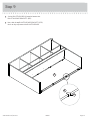
å
Insert six METAL PINS (1R) into the SMALL UPRIGHTS (I).
å
Insert the METAL PINS (1R) in one end of the SMALL
UPRIGHTS (I) into the holes in the UPPER SHELF (D).
Step 4
419717 www.sauder.com/servicesPage 8
1R
Finished edge
I
I
I
D

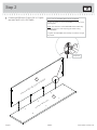
å
Fasten the LOWER SHELF (E) to the SMALL UPRIGHTS (I).
Use nine BLACK 1-7/8" LARGE HEAD SCREWS (2S).
å
Fasten the LOWER BACK (G) to the LOWER SHELF (E).
Tighten four
MINI TWIST-LOCK® FASTENERS.
Step 5
419717www.sauder.com/services
Page 9
I
I
I
E
G
BLACK 1-7/8" FLAT HEAD SCREW
(9 used in this step)
2S
Surface with
TWIST-LOCK®
FASTENERS
Surface with MINI TWIST-LOCK® FASTENERS

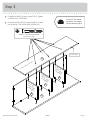
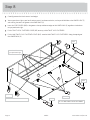
å
Insert four METAL PINS (1R) into the ENDS (A and B).
å
Fasten the ENDS (A and B) to the TOP (C), UPPER SHELF (D),
LOWER SHELF (E), UPPER BACK (F), and LOWER BACK (G).
Tighten eight TWIST-LOCK® FASTENERS and eight MINI
TWIST-LOCK® FASTENERS.
å
NOTE: Be sure the PINS in the ENDS insert into the holes
in the UPPER SHELF (D).
Step 6
419717 www.sauder.com/servicesPage 10
E
G
D
C
1R
1R
Surface
with holes
Surface
without
holes
Side Step: Make
nachos. (Optional, but
recommended.)
A
B
F

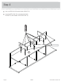
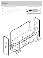
å
Fasten fi ve ANGLE BRACKETS (5G) to the LOWER SHELF (E).
Use fi ve BLACK 9/16" LARGE HEAD SCREWS (1S).
å
Fasten the VALANCE (M) to the LOWER SHELF (E).
Use
fi ve BLACK 9/16" LARGE HEAD SCREWS (1S).
å
NOTE: Turn the SCREWS into the groove of the
VALANCE. Do not overtighten the SCREWS.
å
Fasten the BULLETIN BOARD BRACKETS (63G) to the
LOWER BACK (G). Use eight BROWN 7/16" LARGE HEAD
SCREWS (6S). Do not tighten the SCREWS.
Step 7
419717www.sauder.com/services
Page 11
G
BLACK 9/16" LARGE HEAD SCREW
(10 used in this step)
1S
E
M
5G
63G
63G
BROWN 7/16" LARGE HEAD SCREW
(8 used in this step)
6S

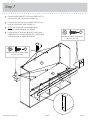
Step 8
419717 www.sauder.com/servicesPage 12
Notch
Notch
Notch
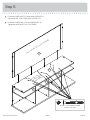
å
Carefully position the Hutch onto its back edges.
å
You may purchase a light at your local hardware store. If you choose to do this, use the pre-drilled holes in the LOWER SHELF (E)
and inserting the cord in the groove in the LOWER BACK (G).
å
Insert the CORD COVERS (66P) in the groove at the top and bottom edges of the LOWER BACK (G) regardless of whether or
not you purchased a light.
å
Push a TWIST-LOCK® FASTENER COVER (61P) onto any visible TWIST-LOCK FASTENER®.
å
Push a MINI TWIST-LOCK® FASTENER COVER (62P) onto the MINI TWIST-LOCK FASTENERS® along the top edge of
the LOWER BACK (G).
E
66P
66P
66P
G
Use these holes for
your purchased light.
61P
61P
61P
61P
To cover TWIST-LOCK® FASTENERS
(14 used)
To cover MINI TWIST-LOCK® FASTENERS
(12 used)
62P

å
Set the BULLETIN BOARD (N) onto the bottom four
BULLETIN BOARD BRACKETS (63G).
å
Now, slide the top BULLETIN BOARD BRACKETS (63G)
down so they wrap around the BULLETIN BOARD.
Step 9
419717www.sauder.com/services
Page 13
N
N
63G

å
Fasten two RAISED HINGES (31H) to one of the RIGHT
DOORS and two RAISED HINGES to one of the LEFT
DOORS (L). Use eight BLACK 1/2" FLAT HEAD
SCREWS (11S)
.
å
Now, fasten the HINGES (53H) to the remaining
DOORS (L and K) as shown below. Use eight BLACK 1/2"
FLAT HEAD SCREWS (11S).
å
NOTE: The DOORS with the RAISED HINGES (31H) will be
the INNER DOORS and the DOORS with the HINGES (53H)
will be the OUTER DOORS.
Step 10
419717 www.sauder.com/servicesPage 14
31H
31H
Raised
area
Raised
area
53H
53H
BLACK 1/2" FLAT HEAD SCREW
(16 used in this step)
11S
K
K
L
L
These DOORS will be
the INNER DOORS.
These DOORS will be
the OUTER DOORS.

Step 11
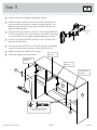
å
Carefully stand your unit upright with help from a friend.
å
Before fastening the DOOR to your unit, be sure the mounting screw is
against the outer end of the slot as shown in the right diagram. If it isn't,
loosen the mounting screw to slide it against the end of the slot. Then
tighten the mounting screw.
å
Fasten the OUTER LEFT DOOR (L) to the LEFT END (B) and OUTER RIGHT
DOOR (K) to the RIGHT END (A). Use the screws in the HINGES. You should
start each SCREW a few turns before completely tightening any of them.
å
Fasten a PULL (12K) to the OUTER DOORS (K and L). Use four GOLD 1"
MACHINE SCREWS (50S).
å
Peel a felt disc from the FELT DISC CARD (1M) and stick it on the corner
of the DOOR where comes in contact with the UPPER SHELF (D).
å
Repeat this step for the INNER DOORS (K and L).
å
See the next step for DOOR adjustments.
419717www.sauder.com/services
Page 15
Slot
Mounting
screw
Hinge
GOLD 1" MACHINE SCREW
(8 used in this step)
50S
A
B
INNER LEFT
DOOR (L)
OUTER RIGHT
DOOR (K)
INNER RIGHT
DOOR (K)
OUTER LEFT
DOOR (L)
1M
12K
12K
D

Step 12
419717 www.sauder.com/servicesPage 16
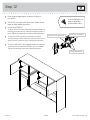
å
Refer to the enlarged diagram to identify the parts on
the HINGES.
å
The DOORS may need some adjustments. Follow the text
below to make needed adjustments.
å
DOOR ADJUSTMENTS:
To adjust the DOORS from side to side (horizontal), loosen the
mounting screw several turns, then turn the adjusting screw in
or out. Tighten the mounting screw after making adjustments.
å
To adjust the DOORS up and down (vertical), loosen both
vertical adjustment screws. Move the DOORS up or down to the
desired location. Tighten the screws after making adjustments.
å
To adjust the DOORS in or out (depth), loosen the mounting
screw one turn and move the DOORS in or out, as needed.
Tighten the mounting screw after making adjustments.
Adjusting screw (horizontal)
Mounting screw (depth)
(vertical adjustment)
If you're doing this to
help a friend, don't
leave without a bite.

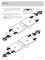
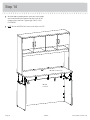
å
If you have not assembled the 401448 Credenza,
assemble it now. If you assembled the 401448, then
you will need to remove the Credenza Top by loosening
the TWIST-LOCK® FASTENERS in the Ends and Back as
shown to the right.
å
Now, fi nish drilling out the four holes in the bottom surface
of the 401448 Credenza Top using a 1/4" drill bit.
å
Then, with the help of another person, carefully lay the Hutch
onto its back. Fasten the Credenza Top to the ENDS (A and B).
Use four BLACK 2-1/4" FLAT HEAD SCREWS (26S) as shown
below.
Step 13
419717www.sauder.com/services
Page 17
BLACK 2-1/4" FLAT HEAD SCREW
(4 used in this step)
26S
401448 Credenza
top removal
Loosen eight
TWIST-LOCK®
FASTENERS.
A
B
401448 Credenza Top

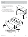
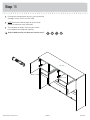
Step 14
å
With the help of another person, stand your Hutch upright
and fasten the 401448 Credenza Top with Hutch to the
Credenza Ends and Back. Tighten eight TWIST-LOCK®
FASTENERS.
å
NOTE: Be sure the METAL PINS insert into the holes in the TOP.
401448
Credenza
401448 Credenza Top
419717 www.sauder.com/servicesPage 18

Step
å
For long term maintenance of your unit, you may touchup
the edges with the TOUCH-UP PEN (10M).
å
NOTE: Please read the back pages of the instruction
booklet for important safety information.
å
This completes assembly. Clean with your favorite
furniture polish or a damp cloth. Wipe dry.
Step 15
No load
60 lbs. total
60 lbs. total
And to celebrate, why not share your success story?
10M
419717www.sauder.com/services
Page 19

A l’usage exclusif du
Canada Noter la date
d’achat de cet élément
et conserver le livret
pour future référence.
Pour contacter Sauder
en ce qui concerne cet
élément, faire référence
au numéro de lot et
numéro de modèle en
appelant notre numéro
sans frais.
Lot nº : ____________
Date de
l’achat: ____________
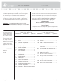
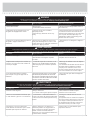
LISTE DE PIÈCES
REFERENCE DESCRIPTION QUANTITÉ
LISTE DE PIÈCES
REFERENCE DESCRIPTION QUANTITÉ
NOUS SOMMES LA POUR VOUS AIDER!
Nous faisons de notre mieux pour nous assurer que votre meuble
arrive dans d’excellentes conditions. Nos représentants du service
Clientèle sont aimables et prêts à vous aider au cas où une pièce
aurait été endommagée ou manquerait (ou si vous aviez besoin
d’aide pour l’assemblage). NE RAMENEZ PAS LE MEUBLE AU
MAGASIN. Au Canada, composez ce numéro d’appel gratuit:
1-800-523-3987
Du lundi au vendredi, de 9 heures du matin à
5:30 heures du soir (horaire Côte Est)
(sauf jours fériés)
Si une pièce a besoin d’être remplacée, la pièce de remplacement
sera envoyée dans les 48 heures. (Sauf week-ends et jours fériés)
Utilisez les instructions d’assemblage en français avec les
schémas étape par étape du manuel d’instruction en anglais.
Chaque étape en français correspond à la même étape
en anglais. La pièce devant être attachée à l’élément est
représentée en gris sur les schémas de chaque étape pour plus
de précision. Comparer la “Liste de pièces” ci-dessous avec
la “PART IDENTIFICATION” du manuel en anglais pour vous
familiariser avec les pièces avant l’assemblage.
REMARQUE : CE MANUEL D’INSTRUCTIONS CONTIENT
D’IMPORTANTES INFORMATIONS RELATIVES À LA SÉCURITÉ.
À LIRE ET CONSERVER POUR TOUTE RÉFÉRENCE FUTURE.
31H CHARNIÈRE DE REHAUSSE ...............................4
53H CHARNIÈRE .....................................................................4
12K POIGNÉE ............................................................................4
1M FICHE DE TAMPONS EN FEUTRE..................1
10M FEUTRE DE RETOUCHE .........................................1
61P COUVERCLE DE FIXATION
TWIST-LOCK® ...............................................................14
62P COUVERCLE DE PETITE TWIST-LOCK® 12
66P COUVERCLE DE CORDON .................................4
1R GOUPILLE EN MÉTAL ..........................................10
1S VIS TÊTE LARGE 14 mm NOIRE ..................10
2S VIS TÊTE PLATE 48 mm NOIRE ..................15
6S VIS TÊTE LARGE 11 mm MARRON ..............8
11S VIS TÊTE PLATE 13 mm NOIRE ...................16
26S VIS TÊTE PLATE 57 mm NOIRE .....................4
50S VIS À MÉTAUX 25 mm DORÉE .......................8
A EXTRÉMITÉ DROITE ..................................................1
B EXTRÉMITÉ GAUCHE ...............................................1
C DESSUS ...............................................................................1
D TABLETTE SUPÉRIEURE ........................................1
E TABLETTE INFÉRIEURE ..........................................1
F ARRIÈRE SUPÉRIEUR ................................................1
G ARRIÈRE INFÉRIEUR ..................................................1
H GRAND MONTANT ....................................................2
I PETIT MONTANT ........................................................3
J MONTANT CENTRAL ...............................................1
K PORTE DROITE ............................................................2
L PORTE GAUCHE .........................................................2
M LAMBREQUIN .................................................................1
N TABLEAU D'AFFICHAGE .......................................1
7F FIXATION TWIST-LOCK® .....................................14
13F PETITE FIXATION TWIST-LOCK®.................16
5G CONSOLE À ÉQUERRE .........................................5
63G CONSOLE DE TABLEAU D'AFFICHAGE ..8
Surmeuble
419717 www.sauder.com/servicesPage 20
Modèle 4197174
La page charge ...
La page charge ...
La page charge ...
La page charge ...
La page charge ...
La page charge ...
La page charge ...
La page charge ...
-
 1
1
-
 2
2
-
 3
3
-
 4
4
-
 5
5
-
 6
6
-
 7
7
-
 8
8
-
 9
9
-
 10
10
-
 11
11
-
 12
12
-
 13
13
-
 14
14
-
 15
15
-
 16
16
-
 17
17
-
 18
18
-
 19
19
-
 20
20
-
 21
21
-
 22
22
-
 23
23
-
 24
24
-
 25
25
-
 26
26
-
 27
27
-
 28
28


dans d''autres langues
- English: Sauder Via 419717 User manual
- español: Sauder Via 419717 Manual de usuario
Documents connexes
-
Sauder 408951 Assembly Instructions Manual
-
-
-
-
-
-
-
-
-