
Need help? Visit Sauder.com to view video assembly tips or chat with a live rep.
Prefer the phone? Call 1-800-523-3987.
Share your journey!
sauder.com
NOTE: THIS INSTRUCTION
BOOKLET CONTAINS IMPORTANT
SAFETY INFORMATION.
PLEASE READ AND KEEP FOR
FUTURE REFERENCE.
English pg 1-27
Français pg 28-31
Español pg 32-36
Lot # 510604 11/09/17
Purchased: __________________
Be sure to give us a ring before
making any returns. 1-800-523-3987
Welcome to the
big kid desk.
Sit/Stand Desk
Model 422357

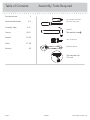
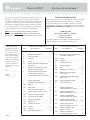
Table of Contents Assembly Tools Required
Part Identifi cation
Hardware Identifi cation
Assembly Steps
Français
Español
Safety
Warranty
Hammer
Not actual size
No. 2 Phillips Screwdriver
Tip Shown Actual Size
3
3-5
6-27
28-31
32-36
37- 38
39
Skip the power trip.
This time.
Short Screwdriver
422357 www.sauder.com/servicesPage 2
Adjustable Wrench

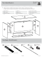
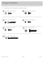
å While not all parts are labeled, some of the parts will have a label or an inked letter on the edge
to help distinguish similar parts from each other. Use this part identifi cation to help identify similar parts.
Now you know
our ABCs.
Part Identifi cation
A RIGHT END (1)
B LEFT END (1)
C MODESTY PANEL (1)
D SHELF (1)
E2 UPRIGHT (1)
F2 LIFT TOP BACK (1)
G LIFT TOP LEFT END (1)
H LIFT TOP RIGHT END (1)
I LIFT TOP (1)
A
B
C
D
E2
F2
G
H
I
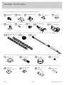
Hardware Identifi cation
(EXTENSION SET SHOWN SEPARATED)
EXTENSION RAIL - 2
J
EXTENSION SLIDE - 2
K
7F
TWIST-LOCK
®
FASTENER - 21
ROD - 1
26A
422357www.sauder.com/services
Page 3
16E
LEVELER - 4

Hardware Identifi cation
å Screws are shown actual size. You may receive extra hardware with your unit.
COTTER PIN - 2
19M
RACK TENSIONER - 2
121M
ACTUATOR PULL - 1
120M
WHEEL - 2
123M
LEFT AND RIGHT RACK
DRIVE SET - 1
122M
CYLINDER - 1
124M
PROPEL NUT - 4
14M
GROMMET CAP - 1
1P
61P
TWIST-LOCK
®
FASTENER COVER - 12
62P
MINI TWIST-LOCK
®
COVER - 1
65P
CORD
MANAGER - 2
SCREW COVER - 4
20P
METAL PIN - 2
1R
CORD CLIP - 2
9P
GROMMET - 3
10P
32G
LEVELER
BRACKET - 4
CABLE BRACKET - 1
72G
CYLINDER BRACKET - 2
71G
13F
MINI TWIST-LOCK
®
FASTENER - 1
422357 www.sauder.com/servicesPage 4
NUT - 4
24M
WASHER - 4
13M

Hardware Identifi cation
å Screws are shown actual size. You may receive extra hardware with your unit.
BLACK 9/16" PAN HEAD SCREW -14
51S
BLACK 9/16" LARGE HEAD SCREW - 12
1S
BROWN 7/16" LARGE HEAD SCREW - 2
6S
BROWN 1-1/2" FLAT HEAD SCREW - 6
14S
SILVER 5/8" FLAT HEAD SCREW - 20
23S
BLACK 1-15/16" FLAT HEAD SCREW - 5
113S
422357www.sauder.com/services
Page 5
BLACK 1-1/4" MACHINE SCREW - 4
93S

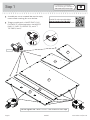
Step 1
Look for this icon. It means a
video assembly tip is available at
www.sauder.com/services/tips
å
Assemble your unit on a carpeted fl oor or on the empty
carton to avoid scratching your unit or the fl oor.
å
To begin assembly, push a SAUDER TWIST-LOCK®
FASTENER (7F) into the large holes in the MODESTY
PANEL (C), SHELF (D), UPRIGHT (E2), and LIFT
TOP ENDS (G and H).
422357 www.sauder.com/servicesPage 6
G
H
Do not tighten the TWIST-LOCK® FASTENERS in this step.
(21 used)
7F
7F
7F
D
E2
C
Scan this QR code or go to this address:
http://qr.sauder.com/?ID=1933
to watch a video on how to assemble your unit.

å
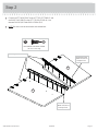
Fasten the LEFT RACK DRIVE to the LIFT TOP LEFT END (G) and
the RIGHT RACK DRIVE to the LIFT TOP RIGHT END (H). Use
fourteen BLACK 9/16" PAN HEAD SCREWS (51S).
å
NOTE: Be sure to use the exact holes with dashed lines.
Step 2
G
H
The LEFT RACK
DRIVE will have an
L stamped here.
The RIGHT RACK
DRIVE will have an
R stamped here.
BLACK 9/16" PAN HEAD SCREW
(14 used in this step)
51S
422357www.sauder.com/services
Page 7
These edges must be even.

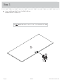
Step 3
å
Push a SAUDER MINI TWIST-LOCK® FASTENER (13F) into
the hole in the LIFT TOP BACK (F2).
Do not tighten the MINI TWIST-LOCK® FASTENER in this step.
13F
F2
422357 www.sauder.com/servicesPage 8

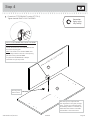
å
Fasten the LIFT TOP BACK (F2) to the LIFT TOP (I).
Tighten the MINI TWIST-LOCK® FASTENER.
Step 4
How to use the SAUDER TWIST-LOCK® FASTENER
and MINI TWISTLOCK® FASTENER
1. Insert the dowel end of the FASTENER into the
hole of the adjoining part.
NOTE: The dowel end of the FASTENER must
remain fully inserted in the hole of the adjoining
part while locking the FASTENER.
2. Tighten the FASTENER with a Phillips
screwdriver as tight as possible.
F2
I
This large hole
must be here.
Surface with MINI TWIST-LOCK® FASTENER
Surface with holes
422357www.sauder.com/services
Page 9
Remember:
Righty tighty.
Lefty loosey.
Meet Part (I). This component has
been engineered to be lighter, stronger,
faster… well ok. Not technically faster.
But defi nitely makes for a sturdier Sit/
Stand Desk that’s easier to assemble
and friendlier to the environment.

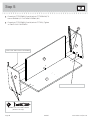
å
Fasten the LIFT TOP ENDS (G and H) to the LIFT TOP BACK (F2).
Use six BROWN 1-1/2" FLAT HEAD SCREWS (14S).
å
Fasten the LIFT TOP ENDS (G and H) to the LIFT TOP (I). Tighten
six TWIST-LOCK® FASTENERS.
Step 5
H
G
BROWN 1-1/2" FLAT HEAD SCREW
(6 used in this step)
14S
14S
I
F2
422357 www.sauder.com/servicesPage 10
Surface with TWIST-LOCK® FASTENERS
Surface with TWIST-LOCK® FASTENERS

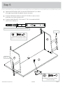
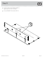
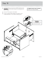
å
Separate the EXTENSION SLIDES (K) from the EXTENSION RAILS (J) as shown
in the upper diagram below. Be prepared, the parts are greasy.
å
Fasten the EXTENSION SLIDES (K) to the LIFT TOP ENDS (G and H). Use ten
SILVER 5/8" FLAT HEAD SCREWS (23S).
å
Fasten the CABLE BRACKET (72G) to the LIFT TOP (I). Use two BLACK 9/16"
LARGE HEAD SCREWS (1S).
Step 6
H
G
Open end
Open end
BLACK 9/16" LARGE HEAD SCREW
(2 used in this step)
1S
SILVER 5/8" FLAT HEAD SCREW
(10 used for the EXTENSION SLIDES)
23S
I
422357www.sauder.com/services
Page 11
Pull down the release lever and pull the SLIDE from the RAIL.
J
K
72G
K
K

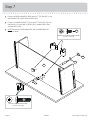
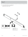
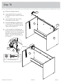
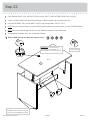
å
Fasten two CORD MANAGERS (65P) to the LIFT TOP BACK (F2). Use
two BROWN 7/16" LARGE HEAD SCREWS (6S).
å
Fasten a CYLINDER BRACKET (71G) to the LIFT TOP BACK (F2). Use
two BLACK 1-1/4" MACHINE SCREWS (93S), two WASHERS (13M),
and two NUTS (24M).
å
NOTE: Position the CORD MANAGERS and CYLINDER BRACKET
exactly as shown.
Step 7
65P
65P
F2
422357 www.sauder.com/servicesPage 12
71G
BLACK 1-1/4" MACHINE SCREW
(2 used in this step)
93S
24M
13M
BROWN 7/16" LARGE HEAD SCREW
(2 used in this step)
6S

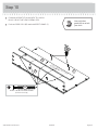
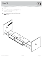
å
Fasten the SHELF (D) to the MODESTY PANEL (C).
Tighten three TWIST-LOCK® FASTENERS.
å
Push two GROMMETS (10P) into the SHELF (D).
Step 8
Surface with
TWIST-LOCK®
FASTENERS
Surface with TWIST-LOCK® FASTENERS
C
D
10P
422357www.sauder.com/services
Page 13

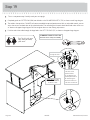
å
Fasten a CYLINDER BRACKET (71G) to the UPRIGHT (E2).
Use two BLACK 1-1/4" MACHINE SCREWS (93S), two
WASHERS (13M), and two NUTS (24M).
Step 9
Surface with TWIST-LOCK® FASTENERS
This hole must be here.
The post on the
BRACKET must be
pointing this direction.
E2
422357 www.sauder.com/servicesPage 14
71G
24M
13M
BLACK 1-1/4" MACHINE SCREW
(2 used in this step)
93S

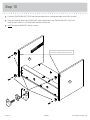
å
Fasten the UPRIGHT (E2) to the SHELF (D). Use fi ve
BLACK 1-15/16" FLAT HEAD SCREWS (113S).
å
Push two CORD CLIPS (9P) into the MODESTY PANEL (C).
Step 10
E2
D
BLACK 1-15/16" FLAT HEAD SCREW
(5 used in this step)
113S
9P
C
422357www.sauder.com/services
Page 15
Now might be a
good time to refresh
your drink.
Surface without TWIST-LOCK®
FASTENERS

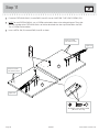
Step 11
å
Fasten the EXTENSION RAILS (J) to the ENDS (A and B). Use ten SILVER 5/8" FLAT HEAD SCREWS (23S).
å
NOTE: For each EXTENSION RAIL, turn a SCREW into the holes shown in the enlarged diagram. Then, slide
the inner cartridge of the EXTENSION RAIL in to fi nd the other holes that lines up with the hole in the END.
Turn a SCREW into these holes.
å
Insert a METAL PIN (1R) into each END (A and B) as shown.
Open end
Open end
1R
A
B
J
J
These four small
holes must be here.
422357 www.sauder.com/servicesPage 16
SILVER 5/8" FLAT HEAD SCREW
(10 used in this step)
23S
These four small
holes must be here.

å
NOTE: You will need a short screwdriver in this step.
å
Fasten the ENDS (A and B) to the MODESTY PANEL (C),
SHELF (D), and UPRIGHT (E2). Tighten twelve
TWIST-LOCK® FASTENERS.
å
NOTE: Be sure the METAL PIN in each END inserts into
the UPRIGHT (E2).
Step 12
A
B
C
D
E2
422357www.sauder.com/services
Page 17

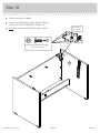
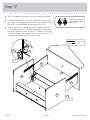
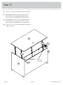
å
Push four LEVELER BRACKETS (32G) over the exact holes shown in the bottom edges of the ENDS (A and B).
å
Using your hammer, gently tap a PROPEL NUT (14M) into the holes in the LEVELER BRACKETS (32G) and
ENDS (A and B). Now, turn a LEVELER (16E) into each PROPEL NUT.
å
NOTE: Position the BRACKETS exactly as shown.
Step 13
Use these holes in the second unit if
you will be standing them side by side.
422357 www.sauder.com/servicesPage 18
A
B
16E
14M
32G

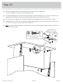
å
Carefully stand your unit upright.
å
Fasten a RACK TENSIONER (121M) to the RIGHT END (A).
Use four BLACK 9/16" LARGE HEAD SCREWS (1S).
å
NOTE: Position the RACK TENSIONER exactly as shown.
Step 14
A
422357www.sauder.com/services
Page 19
BLACK 9/16" LARGE HEAD SCREW
(4 used in this step)
1S
121M
Use the exact
holes shown.

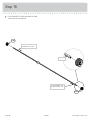
å
Push two WHEELS (123M) onto the ROD (26A)
a few inches in from the end.
Step 15
Flat edge
26A
123M
123M
422357 www.sauder.com/servicesPage 20
Push the WHEEL onto
the ROD a few inches.
Push the WHEEL onto
the ROD a few inches.
La page charge ...
La page charge ...
La page charge ...
La page charge ...
La page charge ...
La page charge ...
La page charge ...
La page charge ...
La page charge ...
La page charge ...
La page charge ...
La page charge ...
La page charge ...
La page charge ...
La page charge ...
La page charge ...
La page charge ...
La page charge ...
La page charge ...
La page charge ...
-
 1
1
-
 2
2
-
 3
3
-
 4
4
-
 5
5
-
 6
6
-
 7
7
-
 8
8
-
 9
9
-
 10
10
-
 11
11
-
 12
12
-
 13
13
-
 14
14
-
 15
15
-
 16
16
-
 17
17
-
 18
18
-
 19
19
-
 20
20
-
 21
21
-
 22
22
-
 23
23
-
 24
24
-
 25
25
-
 26
26
-
 27
27
-
 28
28
-
 29
29
-
 30
30
-
 31
31
-
 32
32
-
 33
33
-
 34
34
-
 35
35
-
 36
36
-
 37
37
-
 38
38
-
 39
39
-
 40
40


dans d''autres langues
- English: Sauder 422357 User manual
- español: Sauder 422357 Manual de usuario
Documents connexes
-
Sauder 419321 Manuel utilisateur
-
-
-
-
-
-
-
-
-