
sauder.com
Dresser
Model 422893
NOTE: THIS INSTRUCTION
BOOKLET CONTAINS IMPORTANT
SAFETY INFORMATION.
PLEASE READ AND KEEP FOR
FUTURE REFERENCE.
Enlish p 1-28
Français p 29-32
Español p 33-36
Lot # 530655 06/19/19
Purchased: __________________
sauder.com
CONTACT US FIRST
BEFORE MAKING ANY RETURNS TO THE STORE.
Share your journey!
sauder.com
CONTACT US FIRST
BEFORE MAKING ANY RETURNS TO THE STORE.
Visit sauder.com/service to order replacement parts, view video assembly tips, or chat with a live rep.
Prefer the phone? Give us a rin at
1-800-523-3987.
Customer Service is available Monday-Friday - 9 a.m. to 5:30 p.m. EST (except holidays)
WARNING
CHOKING HAZARD - Small Parts
Not for children under 3 years.
Adult assembly required.

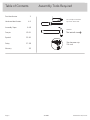
Table of Contents Assembly Tools Required
3
4-5
6-28
29-32
33-36
37-38
39
Part Identifi cation
Hardware Identifi cation
Assembly Steps
Français
Español
Safety
Warranty
Hammer
Not actual size
No. 2 Phillips Screwdriver
Tip Shown Actual Size
Skip the power trip.
This time.
422893 www.sauder.com/servicePae 2

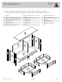
Part Identifi cation
å While not all parts are labeled, some of the parts will have a label or an inked letter on the ede
to help distinuish similar parts from each other. Use this part identifi cation to help identify similar parts.
A END (2)
B RIGHT FRONT/LEFT REAR LEG (2)
C LEFT FRONT/RIGHT REAR LEG (2)
D CENTER LEG (1)
D68 DRAWER BACK (6)
D132 RIGHT DRAWER SIDE (6)
D138
LEFT DRAWER SIDE (6) - 1 with label
D730 DRAWER BOTTOM (6)
E UPRIGHT (1)
F BOTTOM (1)
G SKIRT (2)
H TOP (1)
J RIGHT DRAWER FRONT (3)
K LEFT DRAWER FRONT (3)
L BACK (1)
M65
DRAWER BRACE (6)
(Hidden part usin recycled
material. Color may vary.)
Now you know
our ABCs.
422893www.sauder.com/service
Pae 3
A
B
C
D
E
F
G
H
J
K
L
M65
D132
D68
D138
D730
B
C
G
M65
D132
D68
D138
D730
A

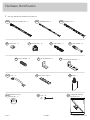
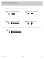
Hardware Identifi cation
å You may receive extra hardware with your unit.
PULL - 6
149K
10A
SLIDE CAM - 12 HIDDEN CAM - 33
1F
CAM SCREW - 22
8F
WOOD DOWEL - 5
15F
METAL BRACKET - 4
4G 19G
LARGE METAL BRACKET - 1
FELT DISC CARD - 2
1M
GLUE - 1
54M
BROWN PLASTIC
WASHER - 12
151M
422893 www.sauder.com/servicePae 4
40DA
UNIVERSAL CABINET RAIL - 12
40DC
DRAWER RIGHT - 6
40DD
DRAWER LEFT - 6
NAIL - 44
1N
CAM DOWEL - 11
2F
FURNITURE TIPPING
RESTRAINT KIT - 1
97

Hardware Identifi cation
å Screws are shown actual size. You may receive extra hardware with your unit.
422893www.sauder.com/service
Pae 5
BLACK 9/16" LARGE HEAD SCREW - 10
1S 3S
GOLD 5/16" FLAT HEAD SCREW - 48
30S
BLACK 1-9/16" FLAT HEAD SCREW - 30 SILVER 1/4" MACHINE SCREW - 12
61S
BLACK 1-15/16" FLAT HEAD SCREW - 3
113S

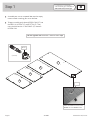
Step 1
Look for this icon. It means a
video assembly tip is available at
www.sauder.com/service/tips
å
Assemble your unit on a carpeted fl oor or on the empty
carton to avoid scratchin your unit or the fl oor.
å
To bein assembly, push eleven HIDDEN CAMS (1F) into
the ENDS (A), UPRIGHT (E), and BOTTOM (F). Then,
insert the metal end of a CAM DOWEL (2F) into each
HIDDEN CAM.
422893 www.sauder.com/servicePae 6
A
A
E
F
Insert the metal end of the CAM
DOWEL into the HIDDEN CAM.
Arrow
Arrow
1F
2F
(11 used)
Do not tihten the HIDDEN CAMS in this step.

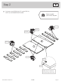
å
Push twenty-two HIDDEN CAMS (1F) into the ENDS (A),
SKIRTS (G), and DRAWER BRACES (M65).
Step 2
422893www.sauder.com/service
Pae 7
Arrow
1F
Arrow
1F
The arrow in the HIDDEN
CAM must point toward the
hole in the ede of the board.
Hole
1F
Arrow
1F
Arrow
(22 used)
Arrow
A
G
M65
G
M65
A
M65
M65
M65
M65
Some assembly
(and snacks) required.

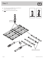
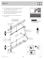
Step 3
å
Turn twenty-two CAM SCREWS (8F) into the LEGS (B, C,
and D) and DRAWER FRONTS (J and K).
å
NOTE: Be sure to use the exact holes shown.
422893 www.sauder.com/servicePae 8
8F
B
C
D
J
K
B
C
J
K
J
K
8F
(22 used)
8F
Do not use these holes.

å
First, fi ll the holes in two of the LEGS (B and C) 1/4 to 1/2 full
with GLUE (54M). Then, insert the WOOD DOWELS (15F)
into the holes. Wipe away the excess GLUE.
å
Now, fi ll the holes in one of the ENDS (A) 1/4 to 1/2 full with
GLUE. Then, insert the WOOD DOWELS in the LEGS into
these holes. Wipe away the excess GLUE.
å
Fasten the two LEGS (B and C) to this END (A). Tihten six
HIDDEN CAMS.
Step 4
422893www.sauder.com/service
Pae 9
Fill the holes 1/4 to 1/2 full with GLUE.
Inspect the parts thorouhly before
assemblin. Disassembly of lued
parts is extremely di cult.
Caution
!
54M
15F
A
Surface with
HIDDEN CAMS
Ede with
CAM DOWELS
B
C
1
2
These surfaces
should be even.
This END (A) will
be the left END.
15F
The LEGS
will overhan
this ede.
This CAM SCREW
must be here.
This hole must be here.

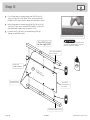
Step 5
422893 www.sauder.com/servicePae 10
Fill the holes 1/4 to 1/2 full with GLUE.
Inspect the parts thorouhly before
assemblin. Disassembly of lued
parts is extremely di cult.
Caution
!
This END (A) will
be the riht END.
å
First, fi ll the holes in the remainin two LEGS (B and C)
1/4 to 1/2 full with GLUE (54M). Then, insert the WOOD
DOWELS (15F) into the holes. Wipe away the excess GLUE.
å
Now, fi ll the holes in the remainin END (A) 1/4 to 1/2 full
with GLUE. Then, insert the WOOD DOWELS in the LEGS
into these holes. Wipe away the excess GLUE.
å
Fasten the LEGS (B and C) to the remainin END (A).
Tihten six HIDDEN CAMS.
A
Surface with
HIDDEN CAMS
C
B
These surfaces
should be even.
15F
15F
The LEGS
will overhan
this ede.
This CAM SCREW
must be here.
This hole must be here.
54M
Ede with
CAM DOWELS

Step Step 6
A
C
A
B
VIEW THE DRAWER GLIDE VIDEO
å
Fasten six UNIVERSAL CABINET RAILS* (40DA) to
the ENDS (A). Use twelve GOLD 5/16" FLAT HEAD
SCREWS (3S) throuh holes #1 and #4.
å
*patent pendin lide system
GOLD 5/16" FLAT HEAD SCREW
(12 used in this step)
3S
3
2
1
1
2
3
4
4
Glide end
3
2
1
4
3
2
1
4
Surface with
HIDDEN CAMS
Surface with
HIDDEN CAMS
1
2
3
4
1
2
3
4
Glide end
422893www.sauder.com/service
Pae 11
This CAM SCREW
must be here.
This CAM SCREW
must be here.

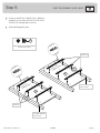
Step
å
Fasten six UNIVERSAL CABINET RAILS* (40DA) to
the UPRIGHT (E). Use twelve GOLD 5/16" FLAT HEAD
SCREWS (3S) throuh holes #1 and #4.
å
*patent pendin lide system
Step 7
GOLD 5/16" FLAT HEAD SCREW
(12 used in this step)
3S
VIEW THE DRAWER GLIDE VIDEO
Glide end
Surface with
HIDDEN CAMS
E
3
2
1
4
3
2
1
4
3
2
1
4
3
2
1
4
1
1
422893 www.sauder.com/servicePae 12
Ede with
CAM DOWELS

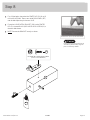
Step Step 8
å
First, fi ll the hole in the end of the CENTER LEG (D) 1/4 to 1/2
full with GLUE (54M). Then, insert the WOOD DOWEL (15F)
into the hole. Wipe away the excess GLUE.
å
Fasten the LARGE METAL BRACKET (19G) to the CENTER
LEG (D). Use one BLACK 9/16" LARGE HEAD SCREW (1S) in
the exact hole shown.
å
NOTE: Position the BRACKET exactly as shown.
Fill the holes 1/4 to 1/2 full with GLUE.
Inspect the parts thorouhly before
assemblin. Disassembly of lued
parts is extremely di cult.
Caution
!
15F
19G
BLACK 9/16" LARGE HEAD SCREW
(1 used for the BRACKET)
1S
D
54M
422893www.sauder.com/service
Pae 13

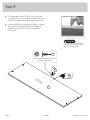
Step
å
First, fi ll the hole in the BOTTOM (F) 1/4 to 1/2 full with
GLUE (54M). Then, insert the WOOD DOWEL (15F) in the
CENTER LEG into the hole. Wipe away the excess GLUE.
å
Fasten the CENTER LEG (D) to the BOTTOM (F). Use one
BLACK 9/16" LARGE HEAD SCREW (1S) throuh the
BRACKET on the CENTER LEG and into the hole in
the BOTTOM.
Step 9
54M
F
BLACK 9/16" LARGE HEAD SCREW
(1 used for the BRACKET)
1S
D
Fill the holes 1/4 to 1/2 full with GLUE.
Inspect the parts thorouhly before
assemblin. Disassembly of lued
parts is extremely di cult.
Caution
!
422893 www.sauder.com/servicePae 14
Surface with
HIDDEN CAMS

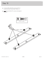
Step Step 10
å
Fasten the METAL BRACKETS (4G) to the SKIRTS (G).
Use four BLACK 9/16" LARGE HEAD SCREWS (1S).
å
NOTE: Be sure the BRACKETS are even with the edes of
the SKIRTS.
BLACK 9/16" LARGE HEAD SCREW
(4 used in this step)
1S
4G
G
G
422893www.sauder.com/service
Pae 15

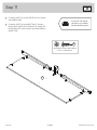
Step Step 11
å
Fasten the SKIRTS (G) to the CENTER LEG (D). Tihten
two HIDDEN CAMS.
å
Fasten the SKIRTS (G) to the BOTTOM (F). Use four
BLACK 9/16" LARGE HEAD SCREWS (1S) throuh the
METAL BRACKETS on the SKIRTS and into the holes in
the BOTTOM.
G
G
D
F
BLACK 9/16" LARGE HEAD SCREW
(4 used for BRACKETS)
1S
Surface with HIDDEN CAMS
Surface with HIDDEN CAMS
Just think. The sooner
you do this, the sooner
you do somethin else.
422893 www.sauder.com/servicePae 16

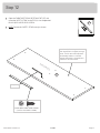
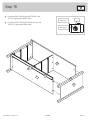
Step Step 12
å
Open the FURNITURE TIPPING RESTRAINT KIT (97) and
fasten the SAFETY STRAP to the TOP (H). Use the provided
BLACK 9/16" LARGE HEAD SCREW.
å
NOTE: Position the SAFETY STRAP exactly as shown.
H
Surface with holes
Meet Part (H). This component has
been enineered to be lihter, stroner,
faster… well ok. Not technically faster.
But defi nitely makes for a sturdier
Dresser that’s easier to assemble and
friendlier to the environment.
422893www.sauder.com/service
Pae 17
BLACK 9/16" LARGE HEAD SCREW
(1 used for the SAFETY STRAP)
97
Safety strap

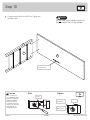
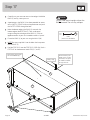
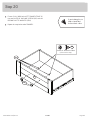
Step
å
Fasten the Left END (A) to the TOP (H). Tihten two
HIDDEN CAMS.
Step 13
A
H
C
The SAFETY STRAP
should be here.
Do not stand the unit upriht without the
BACK fastened. The unit may collapse.
Caution
422893 www.sauder.com/servicePae 18
Start Tighten
Arrow
Minimum
190 derees
Caution
Risk of damae or
injury. HIDDEN CAMS
must be completely
tihtened. HIDDEN
CAMS that are not
completely tihtened
may loosen, and parts
may separate. To
completely tihten:
Arrow
Maximum
210 derees

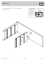
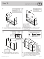
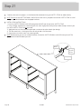
Step Step 14
å
Fasten the UPRIGHT (E) to the TOP (H). Tihten three
HIDDEN CAMS.
E
H
422893www.sauder.com/service
Pae 19
Arrow
Minimum
190 derees
Maximum
210 derees
Surface
with
HIDDEN
CAMS

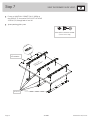
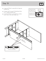
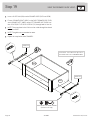
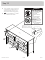
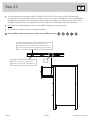
Step
å
Fasten the BOTTOM (F) to the left END (A). Tihten two
HIDDEN CAMS.
å
Fasten the SKIRT (G) to the LEFT FRONT/RIGHT REAR
LEG (C). Tihten one HIDDEN CAM.
å
Fasten the BOTTOM (F) to the UPRIGHT (E). Use three
BLACK 1-15/16" FLAT HEAD SCREWS (113S).
Step 15
E
F
A
G
C
BLACK 1-15/16" FLAT HEAD SCREW
(3 used for the UPRIGHT)
113S
422893 www.sauder.com/servicePae 20
Arrow
Minimum
190 derees
Maximum
210 derees
Surface with
HIDDEN CAMS
La page est en cours de chargement...
La page est en cours de chargement...
La page est en cours de chargement...
La page est en cours de chargement...
La page est en cours de chargement...
La page est en cours de chargement...
La page est en cours de chargement...
La page est en cours de chargement...
La page est en cours de chargement...
La page est en cours de chargement...
La page est en cours de chargement...
La page est en cours de chargement...
La page est en cours de chargement...
La page est en cours de chargement...
La page est en cours de chargement...
La page est en cours de chargement...
La page est en cours de chargement...
La page est en cours de chargement...
La page est en cours de chargement...
La page est en cours de chargement...
-
 1
1
-
 2
2
-
 3
3
-
 4
4
-
 5
5
-
 6
6
-
 7
7
-
 8
8
-
 9
9
-
 10
10
-
 11
11
-
 12
12
-
 13
13
-
 14
14
-
 15
15
-
 16
16
-
 17
17
-
 18
18
-
 19
19
-
 20
20
-
 21
21
-
 22
22
-
 23
23
-
 24
24
-
 25
25
-
 26
26
-
 27
27
-
 28
28
-
 29
29
-
 30
30
-
 31
31
-
 32
32
-
 33
33
-
 34
34
-
 35
35
-
 36
36
-
 37
37
-
 38
38
-
 39
39
-
 40
40


dans d''autres langues
- English: Sauder 422893 Operating instructions
- español: Sauder 422893 Instrucciones de operación
Documents connexes
-
Sauder 423408 Mode d'emploi
-
-
-
-
-
-
-
-
-

