
Sevice Manual
Le service Manual
T1 Gas Braising Pan
T1 Casserole de braisage de gaz
Cleveland
™
1333 East 179th St., Cleveland, Ohio, U.S.A. 44110
Ph: 216.481.4900 Fx: 216.481.3782
www.clevelandrange.com
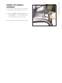
FOR MODELS BUILT
AFTER MAY 2006:
POUR DES MODÈLES
ÉTABLIS APRÈS MAI 2006:
SGL-30-T1
SGL-40-T1
SE95050 Rev. 8
February 2010

FOR THE USER
WARNING: Improper installation, adjustment,
alteration, service or maintenance can cause
property damage, injury or death. Read the
installation and operating instructions thoroughly
before installing or servicing this equipment.
FOR YOUR SAFETY
Do not store or use gasoline or
any other flammable liquids
and vapours in the vicinity of
this or any other appliance.
IMPORTANT
: Post in a prominent location, instructions to be followed in the event the user smells gas.
This information shall be obtained by consulting your local gas supplier.
The following points are to insure the safe installation and operation of this equipment:
• Insure all gas and electrical supplies match rating plate and electrical stickers.
• Keep appliance area free and clear from combustibles.
• Observe all clearance requirements.
• All service must be performed by a qualified Cleveland Range Technician.
• Do not obstruct the flow of combustion and ventilation air.
NOTICE: When this appliance is installed with casters, it must be installed with the casters supplied, a connector
complying with either ANSI Z21.69 • CSA 6.16 and a quickdisconnect device complying with ANSI Z21.41 • CSA
6.9. It must also be installed with restraining means to guard against transmission of strain to the connector, as
specified in the appliance manufacturer's instructions.
RETAIN THIS MANUAL FOR YOUR REFERENCE
POUR L’UTILISATEUR
AVERTISSEMENT: Une installation, un réglage,
une modification, un entretien ou une
maintenance incorrect peut provoquer des dégâts
matériels, des blessures voire la mort. Veuillez lire
soigneusement les instructions d’installation et
de fonctionnement avant d’installer ou d’effectuer
l’entretien de cet équipement.
POUR VOTRE SÉCURITÉ
Ne pas stocker ni utiliser de
l’essence ou tout autre vapeur
ou liquide inflammable à
proximité de cet appareil ou de
tout autre dispositif.
IMPORTANT
: Dans un lieu bien en vue, placez les instructions à suivre dans l'éventualité où l'utilisateur
respirerait du gaz. Ces informations peuvent être obtenues en contactant votre fournisseur de gaz local.
Les points ci-dessous permettent de s’assurer que ce matériel a été installé et fonctionne en toute sécurité:
• Assurez-vous que toutes les alimentations en gaz et en électricité correspondent à la plaque signalétique et aux
étiquettes des propriétés électriques.
• Conservez la zone de l'appareil libre et sans matériaux combustibles.
• Respectez toutes les conditions en terme d’espacement.
• Tous les travaux d’entretien doivent être réalisés par un technicien qualifié sur la gamme de Cleveland.
• N’obstruez pas le flux de combustion ni l’air de ventilation.
AVIS: Si cet appareil doit être installé avec des roulettes, vous devez utiliser les roulettes fournies, ainsi qu’un
connecteur se conformant à ANSI Z21.69 ou CSA 6.16 et un dispositif à débranchement rapide conforme à ANSI
Z21.41 • CSA 6.9. Il doit également être installé avec des éléments de retenue pour prévenir la transmission de
tension au connecteur, comme spécifié dans les instructions du fabricant de l’appareil.
CONSERVEZ CE MANUEL POUR VOTRE RÉFÉRENCE

DANGER / DANGER / PELIGRO / GEFAHR
MAINTENANCE / ENTRETIEN / MANTENIMIENTO / WARTUNG
SERVICING / ENTRETIEN / SERVICIO / WARTUNG
IMPORTANT / IMPORTANT / IMPORTANTE / WICHTIG
CAUTION / ATTENTION / PRECAUCIÓN / VORSICHT
GAS APPLIANCES / APPAREILS À GAZ / APARATOS A GAS / GASGERÄTE
0
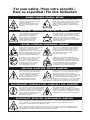
For your safety / Pour votre sécurité /
Para su seguridad / Für Ihre Sicherheit
Shut off power at main fuse disconnect
prior to servicing. / Couper l’alimentation
sur le principal fusible sectionneur avant
l‘entretien. / Apague la alimentación
eléctrica en el fusible desconectador
principal antes de darle servicio. /
Vor der Wartung den Strom am
Haupttrennschalter abschalten.
Ensure kettle is at room temperature and pressure gauge
is showing zero or less prior to removing any fittings. /
S’assurer que le chaudron se trouve dans une
température ambiante et que le manomètre affiche zéro
ou moins avant de déposer les raccords. / Asegúrese de
que la marmita está a temperatura ambiente y el
manómetro está mostrando cero o menos antes de quitar
cualquier accesorio. / Vergewissern, dass der Topf bei
Raumtemperatur ist und das Druckmessgerät Null oder weniger anzeigt.
Inspect unit daily for proper operation.
/ Inspecter le bloc quotidiennement
pour garantir le fonctionnement
normal. / Inspeccione diariamente
el funcionamiento correcto de la
unidad. / Die Einheit täglich auf
richtige Funktion untersuchen.
Do not fill kettle above recommended level marked
on outside of kettle. / Ne pas remplir le chaudron
au-delà du niveau indiqué à l’extérieur. / No llene la
marmita por encima del nivel recomendado
marcado en la parte exterior de la marmita. / Den
Topf nicht über das empfohlene, an der Aussenseite
markierte Niveau füllen.
Surfaces may be extremely hot! Use protective
equipment. / Les surfaces peuvent être
extrêmement chaudes ! Utiliser des
équipements de protection. / ¡Las superficies
pueden estar muy calientes! Utilice equipo
protector. / Die Oberflächen können sehr
heiß werden! Schutzausrüstung tragen.
Keep appliance and area free and clear of
combustibles. / Garder l’appareil et la zone libres et
exempts de combustibles. / Mantenga el aparato y
el área siempre libres de combustibles. / Das Gerät
und Umgebung von brennbaren Stoffen freihalten.
Stand clear of product discharge path when
discharging hot product. / Se tenir loin du chemin de
purge des produits lors de la purge des produits
chauds. / Manténgase alejado de la trayectoria de
descarga del producto al descargar producto
caliente. / Nicht im Produktauslasspfad stehen
während das heiße Produkt entleert wird.
Wear protective equipment when discharging hot
product. / Porter des équipements de protection
lors de la purge des produits chauds. / Utilice
equipo protector al descargar producto caliente. /
Beim entleeren des heißen Produkts
Schutzausrüstung tragen.
Do not lean on or place objects on kettle
lip. / Ne pas adosser ou placer des
objets contre le bord de chaudron. /
No se apoye en la tapa de la marmita
ni coloque objetos sobre ella / Nicht
auf den Topfrand lehnen und dort
keine Gegenstände absetzen.
Do not attempt to operate this appliance during a
power failure. / Ne pas essayer de manœuvrer
cet appareil pendant une panne d’alimentation.
/ No intente poner en marcha este aparato
durante un fallo de alimentación eléctrica. /
Dieses Gerät nicht während eines
Stromausfalls betreiben.
Keep clear of pressure relief discharge. /
Se tenir hors de portée de la purge des
soupapes de surpression. /
Manténgase alejado de la descarga
de presión. / Den Druckablasspfad
v
ermeiden.
Keep hands away from moving parts and pinch
points. / Tenir les mains à l’abri des pièces mobiles
et des angles. / Mantenga las manos lejos de las
piezas movibles y los puntos de presión. / Die
Hände von bewegenden Teilen und Klemmstellen
fernhalten.
The pressure relief valve must be inspected every six months. / La soupape de décharge doit être inspectée à
tous les six mois. / La válvula de descarga de presión debe ser inspeccionada cada seis meses. / Das
Druckablassventil muss alle 6 Monate überprüft werden.
Have an qualified service technician inspect your unit yearly. / L'unité doit être inspectée annuellement par un
technicien de service qualifié. / Haga que un técnico de servicio calificado inspeccione su unidad anualmente.
/ Ein qualifizierter Techniker sollte Ihre Anlage einmal jährlich überprüfen.

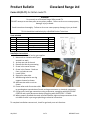
Product Bulletin Cleveland Range Ltd
July 2012 1 of 1 KE603957 rev A
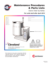
Caster Kit (CS-T1) for Skillet model T1
WARNING
For use only on a Cleveland Range Skillet model T1.
DO NOT attempt to use these parts on any other product. Failure to do so can cause property
damage, Injury or death.
Read instructions thoroughly. Failure to do so can cause property damage, Injury or death.
This kit should be installed only by a Qualified Service Technician.
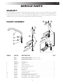
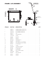
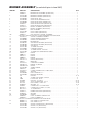
Parts Included
Item Part Number Description Qty.
82 KE53046-1 Caster sleeve 4
80 KE53068-3 Caster 2
81 KE53068-4 Caster c/w brake 2
KE55407 Warning Label 1
KE603957 Instruction sheet, Caster T1 1
KE003646 Strap 1
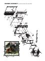
Installation Instructions
1. Disconnect electrical and or gas supplies.
2. Move unit to a location with space
around it to work.
3. Jack up one end of the unit
4. Remove the feet by unscrewing.
5. Screw in the caster sleeves.
6. Screw in the Casters. Brake on
front, no brake on rear.
7. Lower Skillet.
8. Repeat for other side.
9. Add Warning Label to rear leg
support channel as shown.
10. Add restraint cable to unit as
shown.
11. Fasten other end of restraint cable
to guard against transmission of strain to the gas connector or electrical connection.
12. For gas units install gas connections using a connector complying with ANSI Z21.69 *
CGA6.16 and a quick disconnect device complying with ANSI Z21.41 * CGA6.9.
13. When properly installed the strain relief will become tight and stop movement of the
unit before strain is put on gas plumbing or electrical connection.
To complete installation connect unit, check for gas leaks, test unit functions.

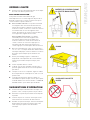
INSPECTION
1. Before unpacking visually inspect the unit for evidence
of damage during shipping.
2. If damage is noticed, do not unpack the unit, follow
shipping damage instructions.
3. Carefully remove unit from shipping carton. Remove
any packing material from unit. After carefully
unpacking check for "concealed" damage. If damage is
noticed, follow "SHIPPING DAMAGE INSTRUCTIONS"
shown below.
4. A protective material has been applied to the stainless
steel panels. This material must be removed
immediately after installation, as heat will melt the
material and make it more difficult to remove.
SHIPPING DAMAGE INSTRUCTIONS
If shipping damage to the unit is discovered or suspected,
observe the following guidelines in preparing a shipping
damage claim.
1. Write down a description of the damage or the reason
for suspecting damage as soon as it is discovered.
This will help in filling out the claim forms later.
2. As soon as damage is discovered or suspected, notify
the carrier that delivered the shipment.
3. Arrange for the carrier's representative to examine the
damage.
4. Fill out all carrier claims forms and have the examining
carrier sign and date each form.
GENERAL
Installation of the kettle must be accomplished by qualified
installation personnel working to all applicable local and
national codes. Improper installation of product could
cause injury or damage.
This equipment is built to comply with applicable standards
for manufacturers. Included among those approval
agencies are: UL, A.G.A., NSF, ASME/N.Bd., CSA, CGA,
ETL, and others. Many local codes exist, and it is the
responsibility of the owner/installer to comply with these
codes.
Observe all clearance requirements to provide proper
make-up air flow. Do not obstruct the flow of combustion
and ventilation air. Check rating plate to ensure that kettle
has been equipped to operate with the type of gas
available at the installation.
Dimensions and clearance requirements are shown on the
Specification Sheet.
CLEARANCE REQUIREMENTS
This unit must be installed in accordance with the
clearances shown on the rating label which is adhered to
the unit.
RIGHT LEFT REAR
Manual Tilt 4” 0 0*
Power Tilt 1” 0 0*
*Allow 3.5” at rear for combustable walls.
FOR YOUR SAFETY. Keep the appliance area free and
clear of combustible materials.
INSTALLATION
1. Position the unit in it's permanent location, and level the
unit by turning the adjustable feet.
2. Once positioned and leveled, permanently secure the
unit's flanged feet to the floor using 5/16" lag bolts and
floor anchors (supplied by the installer). Three bolts are
required to secure each of the flanged feet.
3. Seal joints of flanged feet with a silicone sealant.
GAS
ENSURE THE GAS SUPPLY MATCHES THE KETTLE'S
REQUIREMENTS AS STATED ON THE RATING PLATE.
Installation must conform, with local codes or in the
absence of local codes, with the National Fuel Gas Code
ANSI Z223.1/NFPA 54, or the Natural Gas and Propane
Installation Code, CSA B149.1.
The appliance and its individual shut-off valve must be
disconnected from the gas supply piping system during
any pressure testing of that system at test pressures in
excess of 1/2 psi (3.45 kPa).
The appliance must be isolated from the gas supply piping
system by closing its individual manual shut-off valve
during any pressure testing of the gas supply piping
system at test pressures equal to or less than 1/2 psi (3.45
kPa).
It is recommended that a sediment trap (drip leg) be
installed in the gas supply line. If the gas pressure exceeds
14” water column, a pressure regulator must be installed, to
provide a maximum of 14” water column gas pressure to
the gas control valve.
Connect the gas line to the manual valve located at the
rear of the control box.
Use a gas pipe joint compound which is resistant to L.P.
gas. Test all pipe joints for leaks with soap and water
solution. Ensure that the gas pressure regulator is set for
the manifold pressure indicated on the gas rating plate.
INSTALLATION

ELECTRICAL
NOTE: Wiring diagram is located on the underside of the
unit's control panel.
ENSURE THE ELECTRICAL SUPPLY MATCHES THE
UNIT'S REQUIREMENTS AS STATED ON THE RATING
LABEL.
A cord and plug are supplied with the 115 volt unit. Simply
plug the unit into any grounded outlet rated for a minimum
of 10 amps. The wiring diagram is located on the back of
the console access panel.
When a unit is ordered and built for 208/240 volt, the supply
line must be connected to the wiring terminations located
inside the console. A wiring diagram is attached to the
underside of the control panel.
WARNING: Electrical Grounding Instructions.
This unit is equipped with a three-prong (grounding) plug
for your protection against shock hazard and should be
plugged directly into a properly grounded three-prong
receptacle. Do not cut or remove the grounding prong from
this plug.
Standard supply voltage is 115 volts A.C., however, optional
A.C. voltages can be supplied on special order. A separate
fused disconnect switch must be supplied and installed in
the high voltage electrical supply line. The unit when
installed, must be electrically installed and grounded in
accordance with local codes, or in the absence of local
codes, with National Electrical Code, ANSI/NFPA 70-1990
(USA) or the Canadian Electrical Code, CSA C22.2, Part 1
(Canada).
VENTILATION
Gas fired units are only to be installed under a ventilation
hood in a room which has provisions for adequate make up
air. Further information can be obtained by referring to the
U.S.A. National Fire Protection Associations NFPA96
regulations. These standards have also been adopted by
the National Building Code in Canada..
WATER CONNECTION
(OPTIONAL)
A 1/2" NPT cold water line and/or a 1/2" NPT hot water line
are required if unit is equipped with a single or double
pantry faucet.
INSTALLATION CHECKS
Although the unit has been thoroughly tested before leaving
the factory, the installer is responsible for ensuring the
proper operation of unit once installed.
DO NOT ATTEMPT TO OPERATE THIS UNIT DURING A
POWER FAILURE.
KEEP APPLIANCE AND AREA FREE AND CLEAR OF
COMBUSTIBLES.
1. Supply power to the unit by placing the fused
disconnect switch to the "ON" position.
2. Turn on main gas supply to unit. Open the unit's shut-off
valve (located at lower rear left).
3. Toggle HI / OFF / LO Switch to the "HI" or "LO" position.
4. For your safety the unit is equipped with a power
interrupter which automatically shuts off the gas supply
to the burners whenever the unit is raised more than 8°.
IMPORTANT: Before commencing to cook, ensure the
pan is in the lowered position. Also ensure the cover is
raised.
5. Turn temperature control to maximum. Tilt pan until heat
indicator light turns off and heating system shuts down.
The pan should be on a 5-10° angle.
6. Lower pan. Heat indicator light will re-light and heating
system will re-energize.
7. Unit will continue to heat, heat indicator light will remain
on until temperature is reached. Then the heat indicator
light will cycle OFF indicating the heating system has
shut off. The heat indicator light will continue to cycle
ON and OFF as the heating system cycles ON and OFF
maintaining the desired temperature.
8. Toggle HI / OFF / LO Switch to the "OFF" position.
CLEANING
After installation the unit must be thoroughly cleaned and
sanitized prior to cooking.

HI
L
O
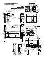
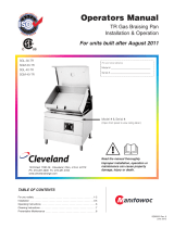
OPERATING
INSTRUCTIONS
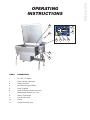
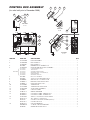
ITEM # DESCRIPTION
1. HI / OFF / LO Switch
2. Power Indicator Light (red)
3. Temperature Dial
4. Heat Indicator Light (yellow)
5. Hand Tilt Wheel
6. Power Tilt Switch (location may vary)
7. Reset Button (location may vary)
8. Manual Tilt Override
9. Gas Shut Off Valve
10. Faucet
11. Tangent Draw-Off Valve
5
8
9
10
4 1 2 3
7
6

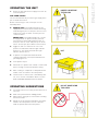
OPERATING THE UNIT
1. Ensure the gas and electrical supply to the unit are
in the ON position.
FOR YOUR SAFETY:
This unit will automatically shut off the gas supply when
pan is raised more than 8°.
Before commencing to cook, ensure pan is in the
lowered position.
2. MANUAL TILT: Cleveland braising pans are
equipped with a manual tilt mechanism for raising
and lowering the pan. To raise pan, raise the cover
and turn the crank clockwise. To lower pan, turn
counterclockwise.
POWER TILT: Cleveland braising pans can also
be equipped with an optional electric power tilt
mechanism for raising and lowering the pan. To
raise pan, raise the cover and press up on the tilt
switch. To lower pan, press down on the tilt switch.
3. Toggle HI / OFF / LO Switch to the "HI" or "LO"
position. The red Power Indicator Light indicates
power is on. The yellow Heat Indicator Light
indicates burners are on.
4. To preheat, set Temperature Dial to desired
cooking temperature. Unit is preheated when the
yellow light goes out.
5. Insert product in pan.
6. If desired, once product has cooked, it can be held
prior to serving at a lower temperature setting.
7. When cooking is completed, set Temperature Dial
and HI / OFF / LO Switch to the OFF position.
8. The best time to clean the unit is immediately after
use, once unit has cooled down. Refer to section
titled "CLEANING INSTRUCTIONS" for details.
OPERATING SUGGESTIONS
1. Turn power switch to the "OFF" position when unit is
not in use.
2. Allow unit to preheat before adding product.
3. Always lift the spring assist cover before activating
the tilt mechanism.
4. During an electrical power interruption, turn Power
Switch to the OFF position. This unit cannot be
made to operate without electrical power.
INSERT LID BEFORE
TILTING PAN
DO NOT HOSE DOWN
THIS AREA
HOT

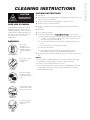
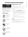
CARE AND CLEANING
Cooking equipment must be cleaned
regularly to maintain its fast, efficient
cooking performance and to ensure its
continued safe, reliable operation. The
best time to clean is shortly after each
use (allow unit to cool to a safe
temperature).
WARNINGS
Do not use
detergents or
cleansers that are
chloride based or
contain quaternary
salt.
Unit should never be
cleaned with a high
pressure spray hose.
Steel wool should
never be used for
cleaning the stainless
steel.
Do not leave water
sitting in unit when
not in use.
Do not use a metal
bristle brush or
scraper.
CLEANING INSTRUCTIONS
CAUTION
SURFACES MAY BE
EXTREMELY HOT!
CLEANING INSTRUCTIONS
1. Turn unit off.
2. Remove drain screen (if applicable). Thoroughly wash and rinse the screen
either in a sink or a dishwasher.
3. Prepare a warm water and mild detergent solution in the unit.
4. Remove food soil using a nylon brush.
5. Loosen food which is stuck by allowing it to soak at a low temperature
setting.
6. Drain unit.
7. Rinse interior thoroughly.
8. If the unit is equipped with a
T
T
a
a
n
n
g
g
e
e
n
n
t
t
D
D
r
r
a
a
w
w
-
-
O
O
f
f
f
f
V
V
a
a
l
l
v
v
e
e
, clean as follows:
a) Disassemble the draw-off valve first by turning the valve knob counter-
clockwise, then turning the large hex nut counter-clockwise until the
valve stem is free of the valve body.
b) In a sink, wash and rinse the inside of the valve body using a nylon
brush.
c)
Use a nylon brush to clean tangent draw-off tube.
d) Rinse with fresh water.
e) Reassemble the draw-off valve by reversing the procedure for
disassembly. The valve's hex nut should be hand tight only.
9. Using mild soapy water and a damp sponge, wash the exterior, rinse, and
dry.
NOTES
➩ For more difficult cleaning applications one of the following can be used:
alcohol, baking soda, vinegar, or a solution of ammonia in water.
➩ Leave the cover off when the kettle is not in use.
➩ For more detailed instructions refer to Stainless Steel Equipment Care and
Cleaning (www.nafem.org/resources/stainlesssteelfinal.doc) on Nafem’s
website (www.nafem.org).
Chloride Cleaners
Wire Brush &
Scrapers
Steel Pads
High Pressure
Spray Hose
Stagnant
Water

MAINTENANCE
WARNING:
Any maintenance or service involving disassembly of components
should be made by a qualified service technician. Ensure gas,
electrical and water supply (if applicable) to the unit are shut off.
!
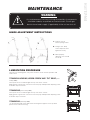
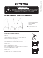
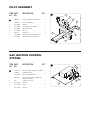
HINGE ADJUSTMENT INSTRUCTIONS
LUBRICATION PROCEDURE
Lubricate the following parts every three months to insure smooth operation and
reduce wear.
TRUNNION HOUSING, WORM SCREW AND TILT GEAR (prior
to May 2006)
These parts are accessed throught the top cover of the console.
Apply grease to gear teeth. Check for excessive play and adjust with adjusting screw
located on top of cross bar.
TRUNNIONS (prior to May 2006)
These parts are accessed throught the top cover of the console.
Apply grease to gear teeth. Check for excessive play and adjust with adjusting screw
located on top of cross bar.
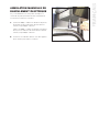
TRUNNION2 (after May 2006)
On the left hand side of the skillet there are two grease nipples on the top back
portion of the trunnion housing.
1. Fully lift cover to
release spring tension.
2. Using a 7/16” deep
socket adjust left and
right bolts evenly.
3. When properly
adjusted, cover should
rest at 70°.

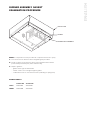
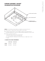
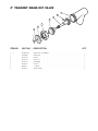
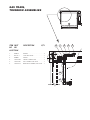
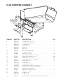
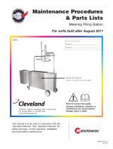
BURNER ASSEMBLY GASKET
EXAMINATION PROCEDURE
NOTE: It is imperative that this procedure be completed at least twice yearly.
1. Turn unit to ON. The burner must be firing during this procedure.
2. Using a stainless steel extension mirror, inspect gasket between burner
pan assembly and skillet pan (sides and front only).
3. Replace gasket if:
- gasket shows signs of deterioration
- a flame can be seen coming through the gasket
- condensation forms on the extension mirror (indicating escaping heat)
GASKET PART #s
30 GALLON 40 GALLON
SIDES SK2472402 SK2472402
FRONT SK2472400 SK2472401
BURNER PAN ASSEMBLY
GASKET
SKILLET PAN

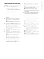
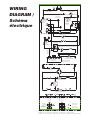
SEQUENCE OF OPERATIONS
When using these instructions refer to the SGL-TI wiring
schematic.
1. 115 VAC is sent through the 3 amp fuse to
■ The primary of the 24 VAC transformer
24 VAC is sent from the secondary of the
24VAC transformer to the Hi/Off/Low Switch.
■ Contacts of the RI Blower Relay
■ The optional Power Tilt Circuit
2. With the Hi/Off/Low switch in the Low position.
■ 24 VAC is sent through the normally closed high
limit switch to the mercury switch.
■ If the unit is in the down position then 24 VAC is
sent through mercury switch to pin 9 on the
thermostat.
3. With the Hi/Off/Low Switch in the Hi position 24
VAC is also sent to the Hi terminal on the gas
valve.
■ Gas will not leave the valve until the main gas
valve opens (see step 7).
4. If the steamer is calling for heat the 24 VAC is sent
from pin number 10 to R1 Blower Relay.
■ The normally open contacts of the blower relay
close sending 115 VAC to the blower.
■ The blower turns closing the air switch.
■ 24 VAC is sent through the now closed air switch
to the ignition module.
5. Ignition module sends spark from terminal SP to
the igniter.
6. Ignition module also sends 24 VAC from pins PV
and MV/PV to the pilot coil of the gas valve pins P
and C.
■ Pilot valve opens sending gas to the Pilot
assembly.
■ Spark and gas meet and pilot is ignited.
■ AC current is passed through the flame and
rectified then sent back to the ignition module.
7. If the ignition module reads a minimum of 1.0
micro-amps through the burner ground then 24
VAC is sent from pins MV and MV/PV of the ignition
module to pins M and C on the Gas valve.
■ The main (low) gas valve opens and gas (3.0"
W.C. natural gas or 8.0" W.C. LP) is sent to the
burner.
■ If the unit is in the Hi position (see step 3) 24VAC
will be at the HI terminal and the gas pressure will
be 3.5" W.C. natural or 10.0" W.C. LP.
■ Burner ignites until thermostat is satisfied.
8. When thermostat is satisfied, 24 VAC is removed
from pin 10 on the thermostat and the heat circuit
is de-energized
9. If the unit has the optional Power Tilt option and is
in the down position, 115 VAC is sent from the
customer connect through the circuit breaker and
the up limit switch to the tilt switch.
10. With the tilt switch in switch in the Up position
■ 115 VAC is sent to the Bridge Rectifier
115 VDC is sent from the rectifier through the
30-ohm resistor to the normally open RY10
and RY11 relay contacts.
■ 115 VAC is sent to the RY 10 relay coil.
■ The normally open RY10 contact close and 90
VDC is sent to the DC motor
■ The DC motor is energized and the unit tilts until
the switch is released or the up limit switch opens.
11. With the Tilt switch in the Down position
■ 115 VAC is sent to the Bridge Rectifier
115 DC is sent from the rectifier through the
30-ohm resistor to the normally open RY10
and RY11 relay contacts.
■ 115 VAC is sent to the RY 11 relay coil.
■ The normally open RY 11 contact close and the
polarity of the 90 VDC is reversed.
■ The DC motor is energized and the unit lowers
until the switch is released or the Down limit switch
opens.

POWER TILT MANUAL
OVERRIDE
In case of power failure or malfunction the skillet pan
can be tilted manually following these instructions.
1. (prior to May 2006) - Fit a 10mm SIX point socket
over the Manual Tilt Shaft as shown above.
(after May 2006) - Fit a 1/2” SIX point socket
over the Manual Tilt Shaft as shown above.
2. Turn socket wrench clockwise to empty contents.

INSPECTION
1. Avant de déballer, inspectez visuellement l'unité pour détecter
tout dommage occasionné pendant le transport.
2. Si vous remarquez un dommage, ne déballez pas l'unité et
suivez les instructions sur les dommages liés au transport.
3. Retirez soigneusement l’unité de l’emballage d’expédition.
Enlevez tout matériel d'emballage de l'unité. Après avoir fini le
déballage méticuleux, confirmez l’absence de tout dommage
"non apparent". Lorsqu’un dommage est constaté, suivez les
"Instructions concernant les dommages liés au transport"
présentées ci-dessous.
4. Les panneaux en acier inoxydable ont été traités avec un
matériau protecteur. Ce matériau doit être retiré
immédiatement après l’installation de l’unité puisque la chaleur
va fondre ce matériau et le rendra plus difficile à éliminer.
INSTRUCTIONS CONCERNANT LES
DOMMAGES LIÉS AU TRANSPORT
If shipping damage to the unit is discovered or suspected,
observe the following guidelines in preparing a shipping damage
claim.
1. Faites une description du dommage ou de la raison pour
laquelle vous soupçonnez un dommage dès que vous vous en
rendez compte. Cela permettra de remplir les formulaires de
réclamation par la suite.
2. Dès lors que vous découvrez ou soupçonnez un dommage,
informez le transporteur qui vous a fourni le matériel.
3. Prenez les arrangements nécessaires pour que le
représentant du transporteur examine le dommage.
4. Remplissez tous les formulaires du transporteur et demandez
à son représentant de signer et de dater chaque formulaire.
GÉNÉRAL
L'installation de la chaudière doit être effectuée par du personnel
qualifié pour l'installation et travaillant conformément à tous les
codes locaux et nationaux en vigueur. Une installation incorrecte
du produit peut provoquer des blessures ou des dommages.
Ce matériel a été conçu pour respecter les normes applicables
aux fabricants. Parmi ces organismes d'approbation se trouvent :
UL, A.G.A., NSF, ASME/N.Bd., CSA, CGA, ETL, et autres. Il existe
de nombreux codes locaux, et il est de la responsabilité du
propriétaire/installateur de se conformer à ces codes.
Respectez toutes les conditions d'espacement pour permettre un
débit d'air correct. N’obstruez pas le flux de combustion ni l’air de
ventilation. Vérifiez la plaque signalétique pour vous assurer que la
chaudière a été équipée pour fonctionner avec le type de gaz
disponible dans l'installation.
Les dimensions et les exigences d’espacement sont indiquées
dans la notice technique.
CONDITIONS EN TERMES
D'ESPACEMENT
Cette unité doit être installée conformément aux espacements
indiqués sur la fiche signalétique collée sur l'unité.
DROIT GAUCHE ARRIÈRE
Inclinaison manuelle 4” 0 0*
Inclinaison électrique 1” 0 0*
*Prévoyez 3,5” à l’arrière pour les murs à constitution combustible.
POUR VOTRE SÉCURITÉ. Conservez la zone de l'appareil libre et
sans matériaux combustibles.
INSTALLATION
1. Placez l'unité dans son emplacement définitif, et mettez-la à
niveau en faisant pivoter les pieds réglables.
2. Une fois positionnée et à plat, serrez définitivement les pieds
bridés de l'unité au sol avec des tire-fonds de 5/16" (7,94
mm) et des ancrages pour plancher (fournis par l'installateur).
Ces boulons sont nécessaires pour serrer chaque pied bridé.
3. Scellez les joints des pieds bridés avec un enduit de silicone.
GAZ
ASSUREZ-VOUS QUE L’ALIMENTATION EN GAZ EST
CONFORME AUX EXIGENCES DE LA CHAUDIÈRE, TEL
QU’INDIQUÉ SUR LA PLAQUE SIGNALÉTIQUE.
L'installation doit être conforme aux codes locaux et/ou à la
dernière édition du code national du gaz combustible ANSI Z223.1
(États-Unis) ou à la dernière version des codes d'installation pour
les appareils et le matériel à gaz combustible CAN/CSA B149.1.
L’appareil et son robinet doivent être débranchés des tuyauteries
d’alimentation de gaz pendant tous les tests de pression effectués
sur ce système à des pressions d’essai dépassant 1/2 psi (3,45
kPa).
L’appareil doit être isolé des tuyauteries d’alimentation en gaz en
fermant son robinet individuel pendant les tests de pression
effectués sur ce système à des pressions d’essais équivalentes ou
inférieures à 1/2 psi (3,45 kPa).
Il est recommandé d'installer un piège de sédiments (collecteur de
condensats) dans le conduit d’alimentation en gaz. Si la pression
du gaz dépasse la colonne d'eau de 14" (35,56 cm), un régulateur
de pression doit être installé pour offrir une pression de la colonne
d'eau de 14" (35,56 cm) au maximum à la vanne de commande du
gaz.
Reliez le conduit du gaz à la vanne manuelle située à l'arrière de
l'armoire de commande.
Pour les conduits de gaz, utilisez un produit pour joints résistant au
gaz de pétrole liquéfié. Testez tous les raccords du tuyau pour
détecter les fuites avec une solution d'eau savoneuse. Assurez-
vous que le régulateur de pression de gaz est réglé à la pression
du manifold, tel qu'indiqué sur la plaque signalétique du gaz.
INSTALLATION

ÉLECTRIQUE
NOTE: Le schéma de câblage se trouve sur le dessous
du tableau de commande de l'appareil.
ASSUREZ-VOUS QUE L’ALIMENTATION ÉLECTRIQUE
CORRESPOND AUX EXIGENCES DE L'UNITÉ, TEL
QU’INDIQUÉ SUR LA PLAQUE SIGNALÉTIQUE.
Un cordon et une prise de courant sont fournis avec l'unité
de 115 volts. Il vous suffit de brancher l'unité à une prise à
contact de mise à terre ayant une valeur nominale minimale
de 10 ampères. Le schéma de câblage se trouve à l'arrière
de la console du panneau de service.
Lorsqu'une unité est commandée et construite pour une
tension de 208/240 volts, la ligne d'alimentation doit être
branchée aux raccordements de câblage situés à l'intérieur
de la console. Un schéma de câblage est attaché au
dessous du tableau de commande
AVERTISSEMENT: Instructions concernant la mise à la
terre électrique.
Cet appareil est équipé d'une fiche tripolaire (à terre) pour
garantir votre protection contre tout risque de choc
électrique et doit être branché directement sur une prise
tripolaire convenablement mise à terre. Ne coupez et ne
retirez pas la broche de mise à terre de cette fiche.
La tension d'alimentation standard est de 115 volts CA.
Cependant, d’autres tensions optionnelles en C.A. peuvent
être fournies sur commande spéciale. Un sectionneur à
fusibles distinct doit être fourni et installé sur la ligne
d’alimentation électrique de haute tension. Une fois installé,
l’appareil doit être calibré électriquement et mis à terre
conformément aux codes locaux ou, en l'absence de
codes locaux, selon le Code national de l'électricité,
ANSI/NFPA 70-1990 (États-Unis) ou le Code canadien de
l'électricité, CSA C22.2, Partie 1 (Canada).
VENTILATION
Les unités à gaz doivent être installées uniquement sous
une hotte de ventilation dans un lieu pouvant fournir de l'air
d’appoint adéquat. D'autres informations sont disponibles
en se référant aux règlementations NFPA96 de la «
National Fire Protection Association » contre le feu aux
États-Unis. Ces normes ont également été adoptées par le
« National Building Code » (Code national du bâtiment) au
Canada..
RACCORDEMENT D‘EAU
(EN OPTION)
Une conduite d'eau froide NPT d’1/2" et/ou une conduite
d’eau chaude NPT d’1/2" est requise si l'appareil est
équipé d'un robinet d'évier simple ou double.
VÉRIFICATIONS DE L‘INSTALLATION
Bien que l'unité ait été testée minutieusement avant son
expédition de l'usine, l'installateur est chargé de veiller au
fonctionnement adéquat de l'unité dès son installation.
N’ESSAYEZ PAS D’EXPLOITER CETTE UNITÉ LORS
D’UNE COUPURE DE COURANT.
CONSERVEZ L’APPAREIL ET SON ENTOURAGE
LIBRES ET SANS MATÉRIAUX COMBUSTIBLES.
1. Mettez l'appareil sous tension en positionnant le
sectionneur à fusibles sur «ON».
2. Activez l'alimentation principale en gaz de l'unité.
Ouvrez le robinet de sectionnement de l’appareil (situé
à l’arrière, en bas à gauche).
3. Basculez le commutateur HI / OFF / LO à la position
"HI" ou "LO".
4. Pour votre sécurité, l'appareil est équipé d'un
interrupteur de puissance qui coupe automatiquement
l'alimentation en gaz des brûleurs dès que l'unité est
soulevée de plus de 8°.
IMPORTANT: Avant de commencer la cuisson, vérifiez
que la casserole est en position abaissée. Assurez-vous
aussi que le couvercle est soulevé.
5. Mettez le régulateur de température au maximum.
Inclinez la casserole jusqu'à voir le voyant de
l’indicateur thermique éteint et le système de chauffage
arrêté. La casserole doit avoir un angle d’inclinaison de
5-10°.
6. Abaissez la casserole. Le voyant de l’indicateur
thermique se rallumera et le système de chauffage
redémarrera.
7. La température de l’appareil continuera de monter et le
voyant de l’indicateur thermique restera allumé jusqu'à
atteindre la température voulue. Le voyant de
l’indicateur thermique passera, ensuite, au cycle OFF
indiquant que le système de chauffage s’est arrêté. Le
voyant de l’indicateur thermique ainsi que le système
de chauffage continueront de basculer entre les cycles
ON et OFF pour maintenir la température souhaitée.
8. Basculez le commutateur HI / OFF / LO à la position
"OFF".
NETTOYAGE
Après l'installation, la chaudière doit être entièrement
nettoyée et aseptisée avant la cuisson.

HI
L
O
INSTRUCTIONS
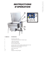
D’OPÉRATION
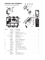
# D’ARTICLE DESCRIPTION
1. Interrupteur HI / OFF / LO
2. Lampe d’indication d’alimentation électrique (rouge)
3. Cadran de la température
4. Témoin de chaleur (jaune)
5. Roue à basculement manuel
6. Interrupteur de basculement électrique (l’emplacement peut varier)
7. Bouton de remise à zéro (l’emplacement peut varier)
8. Annulation du basculement manuel
9. Robinet d’arrêt du gaz
10. Robinet
11. Soupape de soutirage tangentiel
5
8
9
10
4 1 2 3
7
6

OPÉRER L’UNITÉ
1. Assurez-vous que l’alimentation de gaz et électrique
de l’unité sont dans la position ON.
POUR VOTRE PROTECTION :
Cette poêle va arrêter l’alimentation de gaz
automatiquement si la cuvette augmente de plus de 8°.
Avant de commencer la cuisson, assurez-vous que la
cuvette est dans la position abaissée.
2. BASCULEMENT MANUEL : Les poêles Cleveland
sont équipées d’un mécanisme de basculement
manuel pour soulever et baisser la cuvette. Pour
soulever la cuvette, soulevez le couvercle et tournez
la manivelle dans le sens des aiguilles d’une
montre. Pour baisser la cuvette, tournez-la dans le
sens opposé des aiguilles d’une montre.
BASCULEMENT ÉLECTRIQUE : Les poêles
Cleveland peuvent aussi être équipées d’un
mécanisme de basculement électrique pour
soulever et baisser la cuvette. Pour soulever la
cuvette, soulevez le couvercle et appuyez sur
l’interrupteur de basculement. Pour baisser la
cuvette, appuyez sur l’interrupteur de basculement.
3. Basculez l’interrupteur HI / OFF / LO à la position «
HI » ou « LO ». La lampe d’indication d’alimentation
électrique indique que l’unité est allumée. Le témoin
de chaleur jaune indique que les brûleurs sont
allumés.
4. Pour le préchauffage, réglez le cadran de la
température à la température de cuisson désirée.
L’unité est préchauffée lorsque la lampe jaune
s’éteint.
5. Insérez le produit dans la cuvette.
6. Si désiré, une fois que le produit a fini de cuire, il
peut être gardé avant de servir à une température
plus basse.
7. Lorsque la cuisson est complétée, réglez le cadran
de la température et l’interrupteur HI / OFF / LO à la
position OFF.
8. Le meilleur moment pour nettoyer la poêle est
immédiatement après l’emploi, une fois que la poêle
a refroidi. Référez à la section intitulée « CLEANING
INSTRUCTIONS » pour obtenir plus de détails.
SUGGESTIONS D’OPÉRATION
1. Tournez l’interrupteur d’alimentation électrique à la
position « OFF » lorsque la poêle n’est pas utilisée.
2. Permettez à la poêle de préchauffer avant d’ajouter
le produit.
3. Soulevez toujours le couvercle assisté par ressort
avant d’activer le mécanisme de basculement.
4. Pendant une panne électrique, tournez l’interrupteur
d’alimentation électrique à la position OFF. Cette
unité ne peut pas opérer sans alimentation
électrique.
INSÉREZ LE COUVERCLE AVANT
LA CUVETTE BASCULANTE
N’ARROSEZ PAS CETTE
PARTIE
CHAUD

ENTRETIEN ET NETTOYAGE
Le matériel de cuisson peut être nettoyé
régulièrement pour conserver ses
performances de cuisson rapides et efficaces
et assurer un fonctionnement sûr et fiable en
continu. Le meilleur moment pour le
nettoyage est peu de temps après chaque
utilisation (laissez l'unité refroidir à une
température sûre).
AVERTISSEMENTS
N'utilisez pas de
détergents ni de
nettoyant à base de
chlorure ou qui
contiennent du sel
quaternaire.
L'unité ne doit jamais
être nettoyée avec un
tuyau d'arrosage à
haute pression.
N'utilisez jamais de
laine d'acier pour
nettoyer l'acier
inoxydable.
Ne laissez pas d'eau
stagner au fond de
l'unité lorsqu'elle n'est
pas utilisée.
N'utilisez pas de
brosse métallique ni
de raclette.
INSTRUCTIONS DE NETTOYAGE
ATTENTION
LES SURFACES PEUVENT
ÊTRE EXTRÊMEMENT
CHAUDES !
INSTRUCTIONS DE NETTOYAGE
1. Éteignez l'unité.
2. Retirez l'écran de drainage (le cas échéant). Lavez et rincez entièrement l'écran
dans un évier ou un lave-vaisselle.
3. Préparez une solution avec de l'eau chaude et un détergent doux dans l'unité.
4. Enlevez le reste des aliments avec une brosse en nylon.
5. Décollez les aliments coincés en les laissant tremper à un réglage de basse
température.
6. Purgez l'unité
7. Rincez abondamment l'intérieur.
8. Si l'unité est équipée d'une
V
V
a
a
n
n
n
n
e
e
t
t
a
a
n
n
g
g
e
e
n
n
t
t
e
e
à
à
p
p
a
a
s
s
s
s
a
a
g
g
e
e
d
d
i
i
r
r
e
e
c
c
t
t
, nettoyez de la
manière suivante :
a) Démontez la vanne à passage direct, d'abord en tournant le bouton de la
vanne dans le sens contraire des aiguilles d'une montre, puis en tournant le
grand écrou hexagonal dans le sens contraire des aiguilles d'une montre
jusqu'à ce que la tige de la vanne se détache du corps de la vanne.
b) Dans un évier, lavez et rincez l'intérieur du corps de la vanne à l'aide d'une
brosse en nylon.
c) Utilisez une brosse en nylon pour nettoyer le tube tangent de passage
direct.
d) Rincez avec de l'eau fraîche.
e) Remontez la vanne à passage direct en inversant la procédure de
démontage. L'écrou hexagonal de la vanne doit être serré à la main
uniquement.
9. Avec de l'eau douce savonneuse et une éponge humide, lavez l'intérieur, rincez
et séchez.
REMARQUES
➩ Pour les procédés de nettoyage plus difficiles, vous pouvez utiliser l'un des
éléments suivants : alcool, hydrogénocarbonate de sodium, vinaigre ou une
solution d'ammoniac diluée dans de l'eau.
➩ Laissez le couvercle fermé lorsque la chaudière est sous tension.
➩ Pour obtenir des instructions plus détaillées, référez-vous au Nettoyage et entretien
du matériel en acier inoxydable (www.nafem.org/resources/stainlesssteelfinal.doc)
sur le site Internet de Nafem (www.nafem.org)
).
Nettoyants à base
de chlorure
Brosse métallique
et raclettes
Coussinets d'acier
Tuyau d'arrosage à
haute pression
Eau stagnante

ENTRETIEN
AVERTISSEMENT :
Tout entretien qui implique le démontage des composantes devrait être réalisé
par un technicien d’entretien qualifié. Assurez-vous que les alimentations de
gaz, électrique et d’eau (si applicable) à l’unité sont éteintes.
!
INSTRUCTIONS POUR AJUSTER LES CHARNIÈRES
LUBRICATION PROCEDURE
Lubricate the following parts every three months to insure smooth operation and
reduce wear.
COMPARTIMENT DU TOURILLON, VIS TANGENTE ET
EMBRAYAGE DE BASCULEMENT
(avant mai 2006)
Vous pouvez obtenir l’accès à ces pièces par le couvercle supérieur de la console.
Appliquez de la graisse aux dents de l’embrayage. Vérifiez s’il y a trop de jeu et
faites l’ajustement avec la vis d’ajustement située sur la traverse.
TOURILLONS (avant mai 2006)
Sur le côté gauche de la poêle, il y a deux mamelons de graisse sur la portion
arrière du haut du compartiment de tourillons.
Sur le côté droit du chaudron, vous devez retirer le couvercle de la console pour
obtenir l’accès aux deux mamelons de graisse.
TOURILLONS
(après mai 2006) Sur le côté gauche de la poêle, il y a deux mamelons de graisse
sur la portion arrière du haut du compartiment de tourillons.
1. Soulevez le couvercle
complètement pour détacher la
tension des ressorts.
2. En utilisant une douille longue de
7/16 pouces, ajustez les boulons
de gauche et de droite
uniformément.
3. Lorsque le couvercle est ajusté
correctement, il devrait rester à un
angle de 70°.

BURNER ASSEMBLY GASKET
EXAMINATION PROCEDURE
NOTE: Il est essentiel que cette procédure soit complétée au moins deux fois par an.
1. Allumez la poêle. Le brûleur doit être allumé pendant cette procédure.
2. En utilisant un miroir de fouille en acier inoxydable, examinez le joint d’étanchéité entre
l’assemblée du brûleur de la cuvette et la cuvette de la poêle (uniquement les côtés et l’avant).
3. Remplacez la douille d’étanchéité si :
- le joint d’étanchéité montre des signes de détérioration
- vous voyez une flamme à travers le joint d’étanchéité
- il y a une formation de condensation sur le miroir de fouille (ceci indique que la chaleur
s’échappe)
# DE PIÈCES DU JOINT D’ÉTANCHÉITÉ
30 GALLON 40 GALLON
CÔTÉS SK2472402 SK2472402
AVANT SK2472400 SK2472401
ASSEMBLÉE DE LA
CUVETTE DU BRÛLEUR
JOINT D’ÉTANCHÉITÉ
CUVETTE DE LA POÊLE
La page est en cours de chargement...
La page est en cours de chargement...
La page est en cours de chargement...
La page est en cours de chargement...
La page est en cours de chargement...
La page est en cours de chargement...
La page est en cours de chargement...
La page est en cours de chargement...
La page est en cours de chargement...
La page est en cours de chargement...
La page est en cours de chargement...
La page est en cours de chargement...
La page est en cours de chargement...
La page est en cours de chargement...
La page est en cours de chargement...
La page est en cours de chargement...
La page est en cours de chargement...
La page est en cours de chargement...
La page est en cours de chargement...
La page est en cours de chargement...
La page est en cours de chargement...
La page est en cours de chargement...
La page est en cours de chargement...
-
 1
1
-
 2
2
-
 3
3
-
 4
4
-
 5
5
-
 6
6
-
 7
7
-
 8
8
-
 9
9
-
 10
10
-
 11
11
-
 12
12
-
 13
13
-
 14
14
-
 15
15
-
 16
16
-
 17
17
-
 18
18
-
 19
19
-
 20
20
-
 21
21
-
 22
22
-
 23
23
-
 24
24
-
 25
25
-
 26
26
-
 27
27
-
 28
28
-
 29
29
-
 30
30
-
 31
31
-
 32
32
-
 33
33
-
 34
34
-
 35
35
-
 36
36
-
 37
37
-
 38
38
-
 39
39
-
 40
40
-
 41
41
-
 42
42
-
 43
43


Cleveland SE95050 R8 (Skillets T1 Gas) Manuel utilisateur
- Taper
- Manuel utilisateur
- Ce manuel convient également à
dans d''autres langues
Documents connexes
-
 Cleveland SE95050 R8 (Skillets T1 Gas) Manuel utilisateur
-
 Cleveland SE95033 R8 (Skillet TR Gas) Manuel utilisateur
-
Cleveland TMKDL-150-T Manuel utilisateur
-
 Cleveland SE95004 R9 (Kettle Table Top Electric) Manuel utilisateur
-
Cleveland KGT-25-T Mode d'emploi
-
Cleveland KGL-60 60 Gallon Gas Kettle Manuel utilisateur
-
 Cleveland SE95010-1 R11 Manuel utilisateur
-
 Cleveland SE95004 R9 Manuel utilisateur
-
 Cleveland SE95019 R10 (Metering Filling Station) Manuel utilisateur
-
Cleveland KGL-80 Manuel utilisateur


Autres documents
-
Vulcan VG40 Manuel utilisateur
-
Pitco SGM18 w/Filter System Manuel utilisateur
-
Pitco Frialator SG18HP series Manuel utilisateur
-
Vulcan-Hart VGCTS16 Installation & Operation Manuals
-
Wyndham Collection WC-1111-60-SGL Guide d'installation
-
Wyndham Collection WC-1111-42-SGL Guide d'installation
-
Wyndham Collection WC-4141-48-SGL Guide d'installation