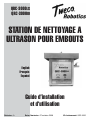
ESAB QRC-3000LS QRC-3000IO Ultrasonic Nozzle Cleaning Station Manuel utilisateur
- Catégorie
- Système de soudage
- Taper
- Manuel utilisateur

50
60
Hz
1
PHASE
GTAW
SMAW
INVERTER
CC
DC
115
V
230
V
ULTRASONIC NOZZLE
CLEANING STATION
English
Français
Español
Revision: A Issue Date: October 27, 2008 Manual No: QRC-3000
Safety and Operating
Instructions
QRC-3000LS
QRC-3000IO

We appreciate your business!
Congratulations on your new Tweco
®
Robotics product. We are proud
to have you as our customer and will strive to provide you with the
best service and reliability in the industry. This product is backed by
our extensive warranty and worldwide service network. To locate your
nearest distributor or service agency, please contact a representative
at the address and phone number in your area listed on the back cover
of this manual, or visit us on the web at www.tweco.com.
This Operating Manual has been designed to instruct you on the correct
use and operation of your Tweco
®
Robotics product. Your satisfaction
with this product and its safe operation is our ultimate concern.
Therefore, please take the time to read the entire manual, especially
the Safety Precautions. They will help you to avoid potential hazards
that may exist when working with this product.
you are in GooD coMpany!
The Brand of Choice for Contractors and Fabricators
Worldwide.
Tweco
®
Robotics is a Global Brand of Welding Products for Thermadyne
Industries Inc. We manufacture and supply to major welding industry
sectors worldwide including; Manufacturing, Construction, Mining,
Automotive, Aerospace, Engineering, Rural and DIY/Hobbyist.
We distinguish ourselves from our competition through market-
leading, dependable products that have stood the test of time. We
pride ourselves on technical innovation, competitive prices, excellent
delivery, superior customer service and technical support, together
with excellence in sales and marketing expertise.
Above all, we are committed to develop technologically advanced
products to achieve a safer working environment within the welding
industry.
50
60
Hz
1
PHASE
GTAW
SMAW
INVERTER
CC
DC
115
V
230
V

WARNING
Read and understand this entire Manual and your employer’s safety practices
before installing, operating, or servicing the equipment. While the information
contained in this Manual represents the Manufacturer’s judgement, the
Manufacturer assumes no liability for its use.
Ultrasonic Nozzle Cleaning Station
Safety and Operating Instructions
Part Number: QRC-3000
Published by:
Thermadyne
®
Industries, Inc.
2800 Airport Rd.
Denton, TX 76207
(940) 566-2000
www.tweco.com
U.S. Customer Care: (800) 426-1888
International Customer Care: (905) 827-9777
Copyright © 2008 Thermadyne Industries, Inc. All rights reserved.
Reproduction of this work, in whole or in part, without written permission of the publisher is
prohibited.
The publisher does not assume and hereby disclaims any liability to any party for any loss or damage
caused by any error or omission in this Manual, whether such error results from negligence, accident,
or any other cause.
Publication Date: October 27, 2008
Record the following information for Warranty purposes:
Where Purchased:
Purchase Date:
Equipment Serial #:

Table of Contents
SECTION 1: INTRODUCTION ..................................................................................1-1
1.01 How to Use this Manual ................................................................
1-1
1.02 Receipt of Equipment ....................................................................
1-1
1.03 Description ....................................................................................1-1
SECTION 2: SAFETY PRECAUTIONS .....................................................................
2-3
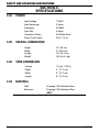
SECTION 3: SPECIFICATIONS ................................................................................3-6
3.01 Power ............................................................................................3-6
3.02 Overall Dimensions .......................................................................
3-6
3.03 Tank Dimensions ...........................................................................
3-6
3.04 Material .........................................................................................3-6
SECTION 4: COMPONENT LAYOUT ........................................................................
4-7
SECTION 5: INSTALLATION AND SETUP ................................................................5-9
5.01 QRC-3000LS - Limit Switch Activated ...........................................5-9
5.02 QRC-3000IO - I/O Controlled .......................................................5-11
SECTION 6: MAINTENANCE .................................................................................
6-13
SECTION 7: PARTS LIST ...................................................................................... 7-14
SECTION 8: STATEMENT OF WARRANTY ............................................................
8-15

1-1
QRC-3000
safety and Operating instructiOns
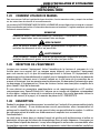
SECTION 1:
INTRODUCTION
1.01 HOW TO USE THIS MANUAL
Information necessary to perform maintenance and service is contained in this manual. This
information is intended for use by technicians or personnel qualified to repair and service this
equipment. The information contained in this document, including performance specifications,
is subject to change without notice. To ensure safe operation, read the entire manual, including
the chapters on safety precautions and warnings.
Throughout this manual, the words WARNING, CAUTION, and NOTE may appear. Pay particular
attention to the information provided under these headings. These special annotations are
easily recognized as follows:
NOTE
NOTE conveys installation, operation, or maintenance information which is
important but not hazard-related.
CAUTION
CAUTION indicates a potentially hazardous situation which, if not avoided, may
result in injury.
WARNING
WARNING indicates a potentially hazardous situation which, if not avoided, could
result in death or serious injury.
1.02 RECEIPT OF EQUIPMENT
When you receive the equipment, check it against the invoice to make sure it is complete and
inspect the equipment for possible damage due to shipping. If there is any damage, notify the
carrier immediately to file a claim. Furnish complete information concerning damage claims
or shipping errors to the location in your area, listed on the back cover of this manual. Include
a full description of the parts in error.
If you want additional or replacement copies of this CD, please contact Tweco® Robotics at
the address and phone number in your area listed on the back cover of this manual. Include
the Manual number (from page i) and CD part number: CDROBOTICS.
1.03 DESCRIPTION
During welding, spatter accumulates on the shielding nozzle and consumables (contact tip,
diffuser). If this spatter is not removed, it will accumulate until the shielding gas is disrupted
causing inadequate gas coverage and porosity in the weld seam. The cleaning station helps
remove and prevent the build up of spatter.
How it works:
The robot moves the gun into the tank filled with anti-spatter fluid and activates the ultrasonic
generator which makes the Piezo transducers vibrate the tank at a high frequency. The vibrating
waves spread throughout the liquid in the tank. When they reach the surface of the weld
consumables, they form compression and decompression waves that create micro-bubbles
(cavitation), which implode. This phenomenon triggers a mechanical action that breaks the
Introduction

1-2
safety and Operating instructiOns
QRC-3000
bond of the weld spatter at the molecular level. This breaks the bond of the spatter from the
nozzle as well as the gas diffuser and tip. It also cools down all the components. The robot
then removes the gun from the tank and a blast of air is pulsed through the gun and out the
gas diffuser. This further removes any loose spatter and excessive fluid. The nozzle, tip and
diffuser are cleaned, cooled and ready to continue welding.
This process has many advantages over conventional nozzle reamers:
Cools, cleans and extends consumable life
Non-contact and no moving parts
Cleans all types and sizes of nozzles
Automatic fluid dispensing
Limit switch activated or robotic I/O controlled
Eliminates programming nozzle to reamer blade
Shop air is not required for operation
Uses standard 120VAC power
The fluid level in the tank is automatically maintained with a peristaltic pump and float switch.
The pump pumps the fluid from standard anti-spatter containers. The container can be placed
on the shelf on the optional stand.
This unit has a two year warranty.
•
•
•
•
•
•
•
•
Introduction

2-3
QRC-3000
safety and Operating instructiOns
SECTION 2:
SAFETY PRECAUTIONS
WARNING
SERIOUS INJURY OR DEATH may result if welding and cutting equipment is
not properly installed, used, and maintained. Misuse of this equipment and other
unsafe practices can be hazardous. The operator, supervisor, and helper must read
and understand the following safety warnings and instructions before installing
or using any welding or cutting equipment, and be aware of the dangers of the
welding or cutting process. Training and proper supervision are important for a
safe work place. Keep these instructions for future use. Additional recommended
safety and operating information is referenced in each section.
WARNING
This product contains chemicals, including lead, or otherwise produces
chemicals known to the State of California to cause cancer, birth defects and
other reproductive harm. Wash hands after handling.
(California Health & Safety Code § 25249.5 et seq.)
ELECTRIC SHOCK CAN CAUSE INJURY OR DEATH
Install and maintain equipment in accordance with the National Electrical Code
(NFPA 70) and local codes. Do not service or repair equipment with power on.
Do not operate equipment with protective insulators or covers removed. Service
or repair to equipment must be done by qualified and/or trained personnel only.
Do not contact electrically live parts. Always wear dry welding gloves that are in
good condition. Aluminized, protective clothing can become part of the electrical path. Keep oxygen
cylinders, chains, wires, ropes, cranes, and hoists away from any part of the electrical path. All
ground connections must be checked periodically to determine if they are mechanically strong,
and electrically adequate for the required current. When engaged in AC welding/cutting under
wet conditions or where perspiration is a factor, the use of automatic controls for reducing the
no load voltage is recommended to reduce shock hazards. Accidental contact must be prevented
when using open circuit voltage exceeding 80 volts AC, or 100 volts DC by adequate insulation
or other means. When welding is to be suspended for any length of time, such as during lunch or
overnight, all electrode holders and electrodes should be removed from the electrode holder and
the power supply should be turned off to prevent accidental contact. Keep MIG-Guns, electrode
holders, Tig torches, Plasma torches, and electrodes away from moisture and water. See safety
and operating references 1, 2, and 8.
SMOKE, FUMES, AND GASES CAN BE DANGEROUS TO YOUR HEALTH
Ventilation must be adequate to remove smoke, fumes, and gases during operation
to protect operators and others in the area. Vapors of chlorinated solvents can form
the toxic gas “Phosgene” when exposed to ultraviolet radiation from an electric arc.
All solvents, degreasers, and potential sources of these vapors must be removed
from the operating area. Use air-supplied respirators if ventilation is not adequate
to remove all fumes and gases. Oxygen supports, and vigorously accelerates fire and should never
be used for ventilation. See safety and operating references 1, 2, 3, and 4.
Safety Precautions

2-4
safety and Operating instructiOns
QRC-3000
ARC RAYS, HOT SLAG, AND SPARKS CAN INJURE EYES AND BURN SKIN
Welding and cutting processes produce extreme localized heat and strong
ultraviolet rays. Never attempt to weld/cut without a federally compliant welding
helmet with the proper lens. A number 12 to 14 shade filter lens provides the
best protection against arc radiation. When in a confined area, prevent the
reflected arc rays from entering around the helmet. Approved shielding curtains
and appropriate goggles should be used to provide protection to others in the surrounding area.
Skin should be protected from arc rays, heat, and molten metal. Always wear protective gloves
and clothing. All pockets should be closed and cuffs sewn shut. Leather aprons, sleeves, leggings,
etc. should be worn for out-of-position welding and cutting, or for heavy operations using large
electrodes. Hightop work shoes provide adequate protection from foot burns. For added protection,
use leather spats. Flammable hair preparations should not be used when welding/cutting. Wear
ear plugs to protect ears from sparks. Where work permits, the operator should be enclosed in
an individual booth painted with a low reflective material such as zinc oxide. See safety and
operating references 1, 2, and 3.
WELDING SPARKS CAN CAUSE FIRES AND EXPLOSIONS
Combustibles reached by the arc, flame, flying sparks, hot slag, and heated
materials can cause fire and explosions. Remove combustibles from the work
area and/or provide a fire watch. Avoid oily or greasy clothing as a spark may
ignite them. Have a fire extinguisher nearby, and know how to use it. If welding/
cutting is to be done on a metal wall, partition, ceiling, or roof, precautions must
be taken to prevent ignition of nearby combustibles on the other side. Do not
weld/cut containers that have held combustibles. All hollow spaces, cavities, and containers
should be vented prior to welding/cutting to permit the escape of air or gases. Purging with inert
gas is recommended. Never use oxygen in a welding torch. Use only inert gases or inert gas
mixes as required by the process. Use of combustible compressed gases can cause explosions
resulting in personal injury or death. Arcing against any compressed gas cylinder can cause
cylinder damage or explosion. See safety and operating references 1, 2, 5, 7, and 8.
NOISE CAN DAMAGE HEARING
Noise from the air carbon-arc process can damage your hearing. Wear protective
hearing devices to ensure protection when noise levels exceed OHSA standards.
Adequate hearing protection devices must be worn by operators and surrounding
personnel to ensure personal protection against noise. See safety and operating
references 1, 2, and 6.
SAFETY AND OPERATING REFERENCES
1. Code of Federal Regulations (OSHA) Section 29, Part 1910.95, 132, 133, 134, 139, 251,
252, 253, 254 and 1000. U.S. Government Printing Office, Washington, DC 20402.
2. ANSI Z49.1 “Safety in Welding and Cutting”.
3. ANSI Z87.1 “Practice for Occupational and Educational Eye and Face Protection”.
4. ANSI Z88.2. “Standard Practice for Respiratory Protection”. American National
Standards Institute, 1430 Broadway, New York, NY 10018.
5. AWS F4.1. “Recommended Safe Practices for Welding and Cutting Containers”.
Safety Precautions

2-5
QRC-3000
safety and Operating instructiOns
6. AWS C5.3. “Recommended Practices for Air Carbon-Arc Gouging and Cutting”.
The American Welding Society, 550 NW Lejeune Rd., P.O. Box 351040, Miami, FL
33135.
7. NFPA 51B. “Fire Prevention in Cutting and Welding Processes”.
8. NFPA-7. “National Electrical Code”. National Fire Protection Association, Battery Park,
Quincy, MA 02269.
9. CSA W117.2. “Safety in Welding, Cutting and Allied Processes”. Canadian Standards
Association, 178 Rexdale Blvd., Rexdale, Ontario, Canada M9W 1R3.
Before installation or operation of the Ultrasonic Nozzle Cleaning Station, please read and
understand all safety precautions listed below. Failure to follow these instructions may result
in personal injury or damage to the equipment.
Only qualified persons should install, operate, maintain and repair this unit.
Do not remove or deface warning and instruction labels from the unit.
Ensure that all equipment in the area is disabled and locked out before setting up,
adjusting or conducting any work.
Ensure that electrical and pneumatic power to the unit is off before setting up, adjusting,
or conducting any work.
Check that electrical and pneumatic connections comply with the codes applicable to
your country and state.
Keep hands away from the unit while it is in operation. Never put your hands or any body
part into the cleaning solution when the cleaner is on.
Use only recommended fluid. Never use flammable or acidic cleaning fluids.
The cleaning solution may become hot. Use caution when handling fluid.
For additional safety information, please refer to the following publications:
ANSI Standard Z49.1, SAFETY IN WELDING AND CUTTING
American Welding Society, 550 LeJeune Rd. P.O. Box 351040, Miami, Fl 33126
ANSI STANDARD, SAFETY FOR ROBOTS AND ROBOT SYSTEMS
American National Standards Institute, 1430 Broadway , New York, NY 10018
NFPA STANDARD 70. NATIONAL ELECTRIC CODE
National Fire Protection Association, Batterymarch Park, Quincy, MA 02269
OSHA 29 CFR 1910, SAFETY AND HEALTH STANDARDS
Superintendent of Documents, U.S. Government Printing Office, Washington, D.C. 20402
•
•
•
•
•
•
•
•
Safety Precautions

3-6
safety and Operating instructiOns
QRC-3000
SECTION 3:
SPECIFICATIONS
3.01 POWER
Input Voltage 120VAC
Input Amperage 3 Amps
Frequency 50/60HZ
Fuse Size 5 Amps
Transducer Power 300 Watts Peak
Power Cord Length 25 ft. (7.5 m)
3.02 OVERALL DIMENSIONS
Height 15" (38 cm)
Width 9" (22.8 cm)
Length 10" (25.4 cm)
Weight 18.5 lb (6.4 kg)
3.03 TANK DIMENSIONS
Volume 1/2 gal. (1.89 L)
Depth 5" (12.7 cm)
Width 5" (12.7 cm)
Length 6" (15.2 cm)
3.04 MATERIAL
Tank 16 gauge 316L Stainless Steel
Enclosure 20 gauge 316L Stainless Steel
NOTE
Specifications subject to change without notification.
Specifications

4-7
QRC-3000
safety and Operating instructiOns
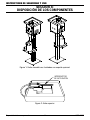
SECTION 4:
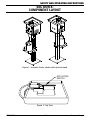
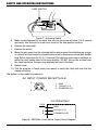
COMPONENT LAYOUT
Figure 1: Isometric Views; shown with optional stand
ACTIVATING
SWITCH
Figure 2: Top View
Component Layout

4-8
safety and Operating instructiOns
QRC-3000
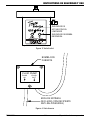
Component Layout
CLEANER ACTIVATION
INDICATOR
PUMP ON INDICATOR
™
Figure 3: Front View
FLUID PUMP
FLUID
IN
FLUID
OUT
PUMP WITH
COVER
FLUID INLET
(TO ANTI-SPATTER
CONTAINER)
Figure 4: Rear View

5-9
QRC-3000
safety and Operating instructiOns
SECTION 5:
INSTALLATION AND SETUP
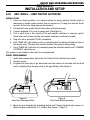
5.01 QRC-3000LS - LIMIT SWITCH ACTIVATED
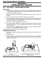
INSTALLATION
1. Place the cleaning station on a secure surface by using optional location plate or
fabricating a simple guide bracket from an angle iron. If using the optional stand,
mount it to the floor using appropriate anchors.
2. Fill tank with anti-spatter fluid to the bottom of the float guard.
3. Connect supplied 10 ft. hose to pump inlet. (See Figure 4)
4. Drill a small hole in the cap/lid of the anti-spatter container or remove cap/lid.
Place other end of hose into the anti-spatter container (cut hose to length).
5. Plug unit into a grounded 120VAC receptacle.
6. Red “PUMP ON” light should come on indicating that the pump is filling the tank to
the proper level. This may take several minutes. The pump is self priming.
7. Once “PUMP ON” light turns off, manually move the activating switch until “CLEANER
ACTIVATED” light turns on.
The system is now ready for the robot to be programmed.
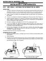
ROBOT PROGRAMMING
1. Install new consumables and verify Tool Center Point is defined accurately.
2. Remove nozzle.
3. Program the robot path to go above the tank then down into the tank until the fluid
level is slightly below the gas holes in the gas diffuser. (See Figure 6)
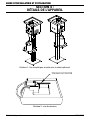
Figure 5:
Insert into Cleaning Station
Figure 6:
Fluid Level below gas holes
4. Move the gun towards the activating switch until Cleaner Activate light comes on.
Move the gun an additional 1/4" further. (See Figure 7, Page 10).
Installation and Setup

5-10
safety and Operating instructiOns
QRC-3000
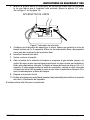
LIMIT SWITCH
Figure 7: Activating Switch
5. Make a wait statement for as much time as your cycle time will allow (2 to 3 second
minimum). Use fine point or small zero zones for the final position location.
6. Reverse the robot path.
7. Replace the nozzle.
8. Move the gun away from the cleaning station and program the shielding gas (purge)
or optional air-blast control to provide a burst of air to remove any excess anti-spatter
fluid. Set air-blast time for 0.5 to 1.0 second. The blast can occur over a container or
while the robot travels back to the home position. DO NOT turn on the air-blast over
the cleaning station. Doing so may displace the fluid in the tank!
9. Return home.
10. Test the program in Teach mode (low speed) to verify the robot path and that the
cleaner activates.
The system is now ready for production.
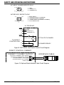
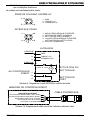
3
2
1
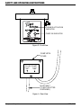
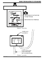
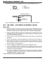
AC INPUT POWER RECEPTACLE
120VAC (L1)
2
COMMON (L2)
1
3
ULTRASONIC
3 PIN
GND
1 - GND
2 - 120VAC (L1)
3 - COMMON (L2)
Figure 8: QRC3000LS Limit Switch Control Circuit Diagram
Installation and Setup

5-11
QRC-3000
safety and Operating instructiOns
5.02 QRC-3000IO - I/O CONTROLLED
INSTALLATION
1. Place cleaning station on a secure surface
by using optional location plate or fabricating
a simple guide bracket from an angle iron. If using the optional stand, mount it to the
floor using appropriate anchors.
2. Wire interface cable (end-user supplied) to the robot controller 24VDC output, which
is located on the back of the unit above the power connector. (Figure 9)
3. Fill tank with anti-spatter fluid to the bottom of the float guard.
4. Connect supplied 10 ft. hose to pump inlet. (See Figure 4)
5. Drill a small hole in the cap/lid of the anti-spatter container or remove cap/lid.
Place other end of hose into the anti-spatter container (cut hose to length).
6. Plug unit into grounded 120VAC receptacle.
7. Red “PUMP ON” light should come on indicating that the pump is filling the tank to
the proper level. This may take several minutes. The pump is self priming.
8. Once “PUMP ON” light turns off, manually set the robot output to activate the cleaner.
“CLEANER ACTIVATED” light should turn on.
The system is now ready for the robot to be programmed.
ROBOT PROGRAMMING
1. Install new consumables and verify Tool Center Point is defined accurately.
2. Remove nozzle.
3. Program the robot path to go above the tank.
4. Program the output to activate the cleaner.
5. Program the robot path so the gun goes into the tank until the anti-spatter fluid level
is slightly below the gas holes in the gas diffuser. (See Figure 6, Page 9).
6. Make a wait statement for as much time as your cycle time will allow (2 to 3 second
minimum). Use fine point or small zero zones for the final position location.
7. Reverse the robot path.
8. Replace the nozzle.
9. Move the gun away from the the cleaner and program the shielding gas (purge) or
optional air-blast control to provide a burst of air to remove any excess anti-spatter
fluid. Set air-blast time for 0.5 to 1.0 second. The blast can occur over a container or
while the robot travels back to the home position. DO NOT turn on the air-blast over
the the cleaner. Doing so may displace the fluid in the tank!
10. Return home.
11. Test the program in Teach mode (low speed) to verify the robot path and that the
cleaner activates.
The system is now ready for production.
Installation and Setup

5-12
safety and Operating instructiOns
QRC-3000
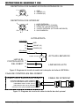
3
2
1
AC INPUT POWER RECEPTACLE
3
4
5
2
1
INTERFACE RECEPTACLE
+
CR
120VAC (L1)
2
24VDC @ 25mA.
COMMON (L2)
1
3
ULTRASONIC
4
1
5 PIN
3 PIN
GND
TO ROBOT
CONTROLLER
2
3
CLEANER READY
ACTIVATE CLEANER
1 - GND
2 - 120VAC (L1)
3 - COMMON (L2)
1 - 0VDC INPUT
2 - CLEANER READY (COMMON)
3 - CLEANER READY (SIGNAL)
4 - +24VDC INPUT (ACTIVATE CLEANER)
5 - NO CONNECTION
Figure 9: QRC-3000IO Limit Switch Control Circuit Diagram
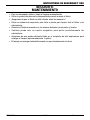
ROBOT CONTROL CABINET
INTERFACE CABLE
CLEANER READY COM. (RED)
SHIELD (BARE)
CONNECT TO ROBOT OUTPUT
ACTIVATE CLEANER +24DC (BLACK)
ACTIVATE CLEANER 0VDC (WHITE)
CLEANER READY SLG.(GREEN)
Figure 10: Optional Robot Interface Cable Circuit Diagram
Installation and Setup

6-13
QRC-3000
safety and Operating instructiOns
SECTION 6:
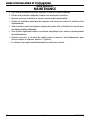
MAINTENANCE
For optimal performance, clean tank weekly.
Use proper personal protection while handling the fluid.
Make sure fluid is not hot before handling!
Use a shop vacuum or plant vacuum system to clean out all the fluid and spatter.
Dispose of fluid in accordance with local city, state and federal requirements.
You can also use a magnet brush to periodically remove spatter.
Make sure there is enough fluid remaining in the anti-spatter container to refill the tank
(approximately 1/2 gallon).
The tank will refill automatically in approximately one hour.
•
•
•
•
•
•
•
•
Maintenance

7-14
safety and Operating instructiOns
QRC-3000
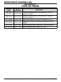
SECTION 7:
PARTS LIST
Part No. Stock No. Description
QRC-3325 3500-1442 Interface Power Cable For QRC-3000IO – 5-pin, 25ft.
QRC-3350 3500-1443 Interface Power Cable For QRC-3000IO – 5-pin, 50ft.
QRC-STAND 3500-1444 Stand For QRC-3000 Series with Z-slot & TCP
QRC-SHELF 3500-1445 Shelf For Anti-Spatter Fluid (Bolts to QRC-STAND)
QRC-PLATE 3500-1446 Mounting Plate For QRC-3000 Series (no stand)
QRC-BRUSH 3500-1447 Brush Magnetic For QRC-3000 Series
Parts List

8-15
QRC-3000
safety and Operating instructiOns
Statement of Warranty
SECTION 8:
STATEMENT OF WARRANTY
LIMITED WARRANTY: THERMADYNE
®
warrants that its products will be free of defects
in workmanship or material. Should any failure to conform to this warranty appear within
the time period applicable to the THERMADYNE products as stated below, THERMADYNE
shall, upon notification thereof and substantiation that the product has been stored, installed,
operated, and maintained in accordance with THERMADYNE’s specifications, instructions,
recommendations and recognized standard industry practice, and not subject to misuse,
repair, neglect, alteration, or accident, correct such defects by suitable repair or replacement,
at THERMADYNE
®
’s sole option, of any components or parts of the product determined by
THERMADYNE
®
to be defective.
THIS WARRANTY IS EXCLUSIVE AND IS IN LIEU OF ALL OTHER WARRANTIES,
EXPRESS OR IMPLIED, INCLUDING ANY WARRANTY OF MERCHANTABILITY OR
FITNESS FOR A PARTICULAR PURPOSE.
LIMITATION OF LIABILITY:
THERMADYNE
®
shall not under any circumstances be liable for
special or consequential damages, such as, but not limited to, damage or loss of purchased or
replacement goods, or claims of customers of distributor (hereinafter the “Purchaser”) for service
interruption. The remedies of the Purchaser set forth herein are exclusive and the liability of
THERMADYNE
®
with respect to any contract, or anything done in connection therewith such as
the performance or breach thereof, or from the manufacture, sale, delivery, resale, or use of any
goods covered by or furnished by THERMADYNE
®
whether arising out of contract, negligence,
strict tort, or under any warranty, or otherwise, shall not, except as expressly provided herein,
exceed the price of the goods upon which such liability is based.
THIS WARRANTY BECOMES INVALID IF REPLACEMENT PARTS OR ACCESSORIES
ARE USED WHICH MAY IMPAIR THE SAFETY OR PERFORMANCE OF ANY
THERMADYNE PRODUCT.
THIS WARRANTY IS INVALID IF THE PRODUCT IS SOLD BY NON-AUTHORIZED
PERSONS.
This warranty is effective for the time stated in the Warranty Schedule beginning on the date
that the authorized distributor delivers the products to the Purchaser.
Warranty repairs or replacement claims under this limited warranty must be submitted by an
authorized THERMADYNE
®
repair facility within thirty (30) days of the repair. No transportation
costs of any kind will be paid under this warranty. Transportation charges to send products to
an authorized warranty repair facility shall be the responsibility of the Purchaser. All returned
goods shall be at the Purchaser’s risk and expense. This warranty supersedes all previous
THERMADYNE
®
warranties.

8-16
safety and Operating instructiOns
QRC-3000
Statement of Warranty
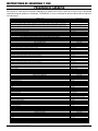
WARRANTY SCHEDULE
The warranty is effective below for the time stated in the Warranty Schedule beginning on the date that the authorized distributor delivers
the products to the purchaser. THERMADYNE
®
reserves the right to request documented evidence of date of purchase.
Engine Driven Welders Parts / Labor
Scout
®
, Raider
®
, Explorer™
Original Main Power Stators and Inductors 3 years / 3 years
Original Main Power Rectifiers, Control P.C. Boards 3 years / 3 years
All Other Original Circuits and Components Including, but not Limited to, Relays, Switches, Contactors, Solenoids, Fans, Power Switch Semi-Conductors 1 year / 1 year
Engines and Associated Components are NOT Warranted by Thermal Arc
®
, Although Most are Warranted by the Engine Manufacturer. SEE THE ENGINE
MANUFACTURERS’ WARRANTY FOR DETAILS.
See the Engine Manufacturers’ Warranty
for Details
GMAW/FCAW (MIG) Welding Equipment Parts / Labor
Fabricator
®
131, 181, 190, 210, 251, 281; Fabstar
®
4030; PowerMaster
®
350, 350P, 500, 500P; Excel-Arc
®
6045; Wire Feeders: Ultrafeed
®
, Porta-feed
®
Original Main Power Transformer and Inductor 5 years / 3 years
Original Main Power Rectifiers, Control P.C. Boards, Power Switch Semi-Conductors 3 years / 3 years
All Other Original Circuits and Components Including, but not Limited to, Relays, Switches, Contactors, Solenoids, Fans, Electric Motors 1 year / 1 year
GTAW (TIG) & Multi-process Inverter Welding Equipment Parts / Labor
160TS, 300TS, 400TS, 185AC/DC, 200AC/DC, 300AC/DC, 400GTSW, 400MST, 300MST, 400MSTP
Original Main Power Magnetics 5 years / 3 years
Original Main Power Rectifiers, Control P.C. Boards, Power Switch Semi-Conductors 3 years / 3 years
All Other Original Circuits and Components Including, but not Limited to, Relays, Switches, Contactors, Solenoids, Fans, Electric Motors 1 year / 1 year
Plasma Welding Equipment Parts / Labor
Ultima
®
150
Original Main Power Magnetics 5 years / 3 years
Original Main Power Rectifiers, Control P.C. Boards, Power Switch Semi-Conductors 3 years / 3 years
Welding Console, Weld Controller, Weld Timer 3 years / 3 years
All Other Original Circuits and Components Including, but not Limited to, Relays, Switches, Contactors, Solenoids, Fans, Electric Motors, Coolant Recirculators 1 year / 1 year
SMAW (Stick) Welding Equipment Parts / Labor
Dragster™ 85
Original Main Power Magnetics 1 year / 1 year
Original Main Power Rectifiers, Control P.C. Boards 1 year / 1 year
All Other Original Circuits and Components Including, but not Limited to, Relays, Switches, Contactors, Solenoids, Fans, Power Switch Semi-Conductors 1 year / 1 year
160S, 300S, 400S
Original Main Power Magnetics 5 years / 3 years
Original Main Power Rectifiers, Control P.C. Boards 3 years / 3 years
All Other Original Circuits and Components Including, but not Limited to, Relays, Switches, Contactors, Solenoids, Fans, Power Switch Semi-Conductors 1 year / 1 year
General Arc Equipment Parts / Labor
Water Recirculators 1 year / 1 year
Plasma Welding Torches 180 days / 180 days
Gas Regulators (Supplied with Power Sources) 180 days / NA
MIG and TIG Torches (Supplied with Power Sources) 90 days / NA
Replacement Repair Parts 90 days / NA
MIG, TIG and Plasma Welding Torch Consumable Items NA / NA
Gas Welding and Cutting Equipment Parts / Labor
Victor
®
Professional 5 years / NA
Oxygen Conservers 2 years / NA
Aluminum Cylinders Lifetime / NA
Cutting Machine Motors 1 year / NA
HP&I Brass Regulators/Manifolds 2 years / NA
HP&I Stainless Regulators/Manifolds 1 year / NA
HP&I Corrosive Gas Regulators/Manifolds 90 days / NA
TurboTorch
®
3 years / NA
CutSkill
®
2 years / NA
Steel Cylinders 1 year / NA
Victor Medical 6 years / NA
Victor VSP 2 years / NA
Firepower
®
MIG Welders 5-2-1 years / NA
Transformers 5 years / NA
Parts Used in Rental Applications
1 year from date sold by seller to authorized
distributor
MIG Torches and Arc Accessories Parts / Labor
Arcair
®
N6000 90 days / NA
Eliminator
®
Spool and Pull Guns 90 days / NA
Robotic Deflection Mounts 90 days / NA
QRM-100 Anti-Spatter Applicator 90 days / NA
TC and TCV Water Coolers 1 year / NA
TSC-96 Smoke Collector 1 year / NA
ESG-1, EPG-CR1, EPG-CR2 Control Boxes for Eliminator Spool & Pull Guns 1 year / NA
QRC-2000 Nozzle Cleaning Stations 1 year / 1 year
QRC-3000 UltraSonic Cleaning Stations 2 years / 2 years
All other products 30 days from date purchaser purchases from seller. 30 days / NA
Plasma Cutting Systems Parts / Labor
Automated Plasma 2 years / 1 year
CutMaster™ 3 years / 3 years
PakMaster
®
XL PLUS 3 years / 1 year
Drag-Gun
®
1 year / 1 year
Drag-Gun Plus 2 years / 1 year
Torches 1 year / 1 year
Consoles, Control Equipment, Heat Exchangers and Accessory Equipment 1 year / 1 year
La page est en cours de chargement...
La page est en cours de chargement...
La page est en cours de chargement...
La page est en cours de chargement...
La page est en cours de chargement...
La page est en cours de chargement...
La page est en cours de chargement...
La page est en cours de chargement...
La page est en cours de chargement...
La page est en cours de chargement...
La page est en cours de chargement...
La page est en cours de chargement...
La page est en cours de chargement...
La page est en cours de chargement...
La page est en cours de chargement...
La page est en cours de chargement...
La page est en cours de chargement...
La page est en cours de chargement...
La page est en cours de chargement...
La page est en cours de chargement...
La page est en cours de chargement...
La page est en cours de chargement...
La page est en cours de chargement...
La page est en cours de chargement...
La page est en cours de chargement...
La page est en cours de chargement...
La page est en cours de chargement...
La page est en cours de chargement...
La page est en cours de chargement...
La page est en cours de chargement...
La page est en cours de chargement...
La page est en cours de chargement...
La page est en cours de chargement...
La page est en cours de chargement...
La page est en cours de chargement...
La page est en cours de chargement...
La page est en cours de chargement...
La page est en cours de chargement...
La page est en cours de chargement...
La page est en cours de chargement...
La page est en cours de chargement...
La page est en cours de chargement...
La page est en cours de chargement...
La page est en cours de chargement...
La page est en cours de chargement...
La page est en cours de chargement...
-
 1
1
-
 2
2
-
 3
3
-
 4
4
-
 5
5
-
 6
6
-
 7
7
-
 8
8
-
 9
9
-
 10
10
-
 11
11
-
 12
12
-
 13
13
-
 14
14
-
 15
15
-
 16
16
-
 17
17
-
 18
18
-
 19
19
-
 20
20
-
 21
21
-
 22
22
-
 23
23
-
 24
24
-
 25
25
-
 26
26
-
 27
27
-
 28
28
-
 29
29
-
 30
30
-
 31
31
-
 32
32
-
 33
33
-
 34
34
-
 35
35
-
 36
36
-
 37
37
-
 38
38
-
 39
39
-
 40
40
-
 41
41
-
 42
42
-
 43
43
-
 44
44
-
 45
45
-
 46
46
-
 47
47
-
 48
48
-
 49
49
-
 50
50
-
 51
51
-
 52
52
-
 53
53
-
 54
54
-
 55
55
-
 56
56
-
 57
57
-
 58
58
-
 59
59
-
 60
60
-
 61
61
-
 62
62
-
 63
63
-
 64
64
-
 65
65
-
 66
66


ESAB QRC-3000LS QRC-3000IO Ultrasonic Nozzle Cleaning Station Manuel utilisateur
- Catégorie
- Système de soudage
- Taper
- Manuel utilisateur
dans d''autres langues
Documents connexes
-
 Tweco Welding and Cutting Operations Manuel utilisateur
-
 Tweco Air-Cooled 350 AMP 450 AMP Water-Cooled 400 AMP 500 AMP PulseMaster™ Mig Gun Manuel utilisateur
-
 Tweco Robotics QRC™-2000 Nozzle Cleaning Station Guide d'installation
-
 Tweco Robotics QRM-100 Anti-Spatter Mist Applicator Guide d'installation
-
 Thermal Dynamics 42 CUTMASTER® Plasma Cutting System Manuel utilisateur
-
 Tweco Robotics QWT-3 Quick Wire Trim Unit Guide d'installation
-
Thermal Dynamics Plasma Cutting System Model Drag-Gun Plus Manuel utilisateur
-
Tweco Robotics Light Weight Quick Robotics Torch Guide d'installation
-
 Tweco Robotics WRS Series 400 AMP 600 AMP Water-Cooled Automation Mig Guns Manuel utilisateur
-
 Tweco Robotics QWT-120 Wire Cutting Station Guide d'installation


