BFT BOTTICELLI BT AV 650 Manuel utilisateur
- Taper
- Manuel utilisateur

D814253 0AN00_01 21-10-22
BOTTICELLI BT AV
650
ISTRUZIONI D’USO E DI INSTALLAZIONE
INSTALLATION AND USER’S MANUAL
INSTRUCTIONS D’UTILISATION ET D’INSTALLATION
INSTALLATIONS-UND GEBRAUCHSANLEITUNG
INSTRUCCIONES DE USO Y DE INSTALACION
GEBRUIKS- EN INSTALLATIEAANWIJZINGEN
AUTOMAZIONI PER PORTE BASCULANTI E SEZIONALI
AUTOMATION FOR OVERHEAD AND SECTIONAL GARAGE DOORS
AUTOMATION POUR PORTES BASCULANTES ET SECTIONALES
GARAGENTORANTRIEB FÜR SCHWING UND SEKTIONALTORE
AUTOMATIZACIONES PARA PUERTAS BASCULANTE Y SECCIONALES
AUTOMATISERINGEN VOOR KANTEL- EN SECTIEDEUREN
Attenzione! Leggere attentamente le “Avvertenze” all’interno! Caution! Read “Warnings” inside carefully! Attention! Veuillez lire attentivement les Avertissements qui se trouvent à l’intérieur!
Achtung! Bitte lesen Sie aufmerksam die „Hinweise“ im Inneren! ¡Atención¡ Leer atentamente las “Advertencias”en el interior! Let op! Lees de “Waarschuwingen” aan de binnenkant zorgvuldig!

1 2
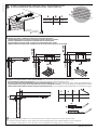
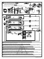
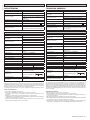
GENERALITÀ
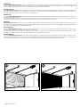
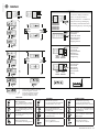
Il sistema BOTTICELLI BT AV 650 è adatto a motorizzare porte sezionali (Fig. 1), porte basculanti debordanti a molle a totale rientranza (Fig. 2).
L’altezza massima della porta basculante non deve superare i 3 metri. L’installazione di facile esecuzione, permette un rapido montaggio senza
alcuna modica alla porta. Il blocco in chiusura è mantenuto dal motoriduttore irreversibile.
GENERAL OUTLINE
The BOTTICELLI BT AV 650 system is suitable for motorising sectional doors (g. 1), protruding fully retracting spring-operated overhead doors
(g. 2). The overhead door must not be higher than 3 metres. Its easy installation allows fast tting without needing the door to be modied. The
irreversible gearmotor keeps the door locked in the closing position.
GENERALITES
Le système BOTTICELLI BT AV 650 est indiqué pour motoriser des portes multi-lames (g. 1), des portes de garage débordantes à ressorts com-
plètement escamotables (g. 2).
La hauteur maximale de la porte de garage ne doit pas dépasser 3 mètres. L’installation, très facile à eectuer, permet un montage rapide sans
aucune modication de la porte. Le blocage en fermeture est maintenu par le motoréducteur irréversible.
ÜBERSICHT
BOTTICELLI BT AV 650 eignet sich mit seinem speziellen Zugarm (Abb. 1) zur Motorisierung von Sektionaltoren (Abb. 2), überstehenden Feder-
Schwingtoren mit Volleinzug. Die Maximalhöhe des Schwingtores darf 3 Meter nicht übersteigen. Die einfach durchzuführende Installation besteht
aus einer schnellen Montage ohne Änderung des Tores.
DATOS GENERALES
El sistema BOTTICELLI BT AV 650 es adecuado para motorizar puertas seccionales (Fig. 1), puertas basculantes desbordantes, completamente
retráctiles, de muelles (Fig. 2) y puertas basculantes de contrapesos.
La altura máxima de la puerta basculante no debe superar los 3 metros. La instalación, de fácil ejecución, permite un rápido montaje sin necesidad
de modicar la puerta. El bloqueo de cierre es mantenido por el motorreductor irreversible.
ALGEMEENHEDEN
Het systeem BOTTICELLI BT AV 650 is geschikt om sectiedeuren (g.1), volledig inspringende overlappende klapdeuren met veer (g.2). De maxi-
mum hoogte van de klapdeur mag de 3 meters niet overschrijden. de installatie kan gemakkelijk worden uitgevoerd, en staat een snelle montage
toe zonder enige wijziging aan de deur. De blokkering in sluiting wordt bekomen door de onomkeerbare reductiemotor.
2 - BOTTICELLI BT AV 650
D814253 0AN00_01

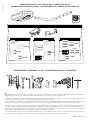
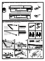
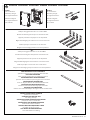
COMPOSIZIONE DEL KIT - KIT COMPOSITION - COMPOSITION DU KIT
ZUSAMMENSETZUNG DES BAUSATZES - COMPOSICIÓN DEL KIT- SAMENSTELLING VAN DE KIT
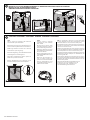
Per installazioni che richiedano che l’operatore operi ad altezze superiori ai 2 metri rispetto al piano sottostante, è obbligatorio l’utilizzo di attrezzature con livelli di sicurezza
maggiori quali ad esempio ponteggi o trabatelli. Per attività extra-Italia vericare preventivamente la specica normativa locale.
For installations that require the operator to operate at heights greater than 2 meters above the oor level, it is mandatory to use equipment with higher safety levels such
as scaolding or rolling towers. For activities outside Italy, check the specic local legislation in advance.
Pour les installations qui exigent que l’opérateur travaille à des hauteurs supérieures à 2 mètres par rapport au plancher, utiliser impérativement des équipements avec
des niveaux de sécurité supérieurs tels qu’échafaudages ou chevalets. Pour les activités à l’étranger, consulter à l’avance les réglementations locales spéciques.
Für Installationen, bei denen in Höhen von über 2 Meter über dem darunterliegenden Boden gearbeitet werden muss, müssen Ausrüstungen mit erhöhtem Sicherheitsniveau verwen-
det werden, wie zum Beispiel Maurerarbeitsbühnen oder fahrbare Gerüste. Überprüfen Sie bei Arbeiten außerhalb Italiens vorher die entsprechenden örtlichen Bestimmungen.
Cuando el operador debe trabajar a más de 2 metros del plano inferior, debe obligatoriamente utilizar equipos con mayores niveles de seguridad, como por ejemplo anda-
mios y caballetes. Para actividades fuera del territorio italiano, consultar previamente las normas locales.
Voor installaties waarbij de operator op een hoogte van meer dan 2 meter boven het onderstaande niveau moet werken, is het verplicht uitrustingen te gebruiken met ho-
gere beveiligingsniveaus, zoals ladders of steigers. Voor activiteiten buiten Italië, moet men vooraf de specieke lokale normen controleren.
Ø5
Ferro
Iron
Fer
Eisen
Hierro
Ijzer
Ø10
Muro
Wall
Mural
Mauer
Pared
Muur
ATTREZZATURE - EQUIPMENT- OUTILS - AUSRÜSTUNG-EQUIPOS - UITRUSTING
*
*
1313
6
PH1/PH2
PH1/PH2
13/17
S10
M8 M8
M8x16
S10
M8x30
M8X60
M8X40
M8x60
4,8x22
3,9x13
6,3x60
BOTTICELLI BT AV 650 - 3
D814253 0AN00_01

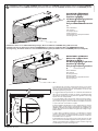
Installazione motore con sotto STANDARD , Motor installation on STANDARD ceiling,Installation moteur sur plafond STANDARD
Installation Motor mit STANDARD-Abdeckung, Instalación del motor con techo ESTÁNDAR, Installatie motor met STANDAARD plafond
Installazione motore con sotto PIU’ ALTO (prolunga) , Motor installation on HIGHER ceiling (with extension)
Installation moteur sur plafond avec hauteur SUPERIEURE (avec rallonge), Installation Motor mit HÖHERER Abdeckung
(Verlängerung) , Instalación del motor con techo MÁS ALTO (alargador), Installatie motor met HOGERE plafond (verlengstuk)
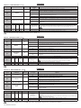
Si consiglia di ssare l’operatore in maniera tale da poter tenere il ramo
anteriore della leva il più possibile orizzontale (vedere gura), fermo re-
stando che andrà vericato, da parte dell’installatore, il rispetto della
normativa riguardante gli impatti.
It is suggested that the operator be set so that the front branch of
the lever is as horizontal as possible (see gure), considering in any
case that the installer must verify that the regulation concerning
impacts must be complied with.
Il est recommandé de xer l’opérateur de manière à pouvoir mainte-
nir la branche avant du levier dans une position la plus horizontale
que possible (voir gure), étant entendu que l’installateur vériera le
respect de la norme concernant les impacts.
Es wird empfohlen den Bediener in einer solchen Weise zu sichern,
dass der vordere Teil des Hebels so horizontal wie möglich (siehe
Abbildung) gehalten wird. Dabei bleibt durch den Installateur zu
prüfen, dass die Rechtsvorschriften bezüglich der Anlagen einge-
halten werden.
Se sugiere jar el operador de modo que se pueda mantener el tramo
delantero de la palanca lo más horizontal que sea posible (ver la gu-
ra), sin perjuicio de que el instalador deberá controlar que cumpla con
la normativa sobre los impactos.
Er wordt aanbevolen om de operator zo te bevestigen dat de voorste arm
van de hendel zo horizontaal mogelijk kan worden gehouden (zie afbe-
elding), op voorwaarde dat de installateur controleert dat de wetgeving
met betrekking tot de impact wordt nageleefd.
*
Non in dotazione
Not supplied
Ne sont pas fournis
Nicht im lieferum
No asignadas en el equipamiento base
Niet meegeleverd
*
Non in dotazione
Not supplied
Ne sont pas fournis
Nicht im lieferum
No asignadas en el equipamiento base
Niet meegeleverd
BILANCIARE IL SEZIONALE!
Balance the sectional door!
Équilibrer la section !
Die Motorgewichte ausgleichen!
¡Equilibrar el seccional!
Breng de sectionaaldeur in evenwicht!
BILANCIARE IL SEZIONALE!
Balance the sectional door!
Équilibrer la section !
Die Motorgewichte ausgleichen!
¡Equilibrar el seccional!
Breng de sectionaaldeur in evenwicht!
200 mm
200 mm
A
110 ÷ 170
4 - BOTTICELLI BT AV 650
D814253 0AN00_01

AA
A B C
2000-2400 2900 3300 min
2400-3000 3500 3900 min
A
C
B
1
110-170
110-170
110-170
170-400
400-500
APT
APT S
X
A
Y
X A Y
>70 170-230 <300 186
266
>70 170-260 <400
*
2
3
186
266
.Accessori non in dotazione!
.Not Supplied accessories!
.Accessoires ne sont pas fournis!
.Nicht Mitgeliefertes Zubehör!
.
No asignadas en el equipamiento base!
.Accessoires Niet meegeleverd
CORRETTO FISSAGGIO DEL BINARIO A SECONDA DELL’ALTEZZA DELLA PORTA DAL SOFFITTO
CORRECT RAIL FIXING, ACCORDING TO THE DOOR’S HEIGHT FROM THE CEILING
FIXATION CORRECTE DU RAIL SELON LA HAUTEUR DE LA PORTE À PARTIR DU PLAFOND
RICHTIGE SCHIENENBEFESTIGUNG GEMÄSS DER HÖHE DER TÜR VON DER DECKE
FIJACIÓN CORRECTA DEL RIEL SEGÚN LA ALTURA DE LA PUERTA RESPECTO AL TECHO
CORRECTE BEVESTIGING VAN DE RAIL AFHANKELIJK VAN DE HOOGTE VAN DE DEUR TOT HET PLAFOND
CORRETTO FISSAGGIO DEL BINARIO IN CASO DI ARCHITRAVE SOPRA LA PORTA
se non è possibile appoggiare il binario alla parete del sezionale:
CORRECT RAIL FIXING IF THERE IS A LINTEL ABOVE THE DOOR
if it is not possible, place the rail on the sectional wall:
FIXATION CORRECTE DU RAIL EN CAS DE LINTEAU AU
s’il n’est pas possible de poser le rail sur la paroi de section:
DESSUS DE LA PORTE-RICHTIGE SCHIENENBEFESTIGUNG BEI TRAGBALKEN ÜBER DER TÜR wenn es nicht möglich ist, die Schiene auf der Trennwand abzustützen:
FIJACIÓN CORRECTA DEL CARRIL EN CASO DE DINTEL EN LA PARTE SUPERIOR DE LA PUERTA si no es posible apoyar el riel a la pared del seccional:
CORRECTE BEVESTIGING VAN DE RAIL IN GEVAL VAN ARCHITRAAF BOVEN DE DEUR het is niet mogelijk om de rail op de wand van de sectionale poort te leggen:
La prolunga potrebbe ridurre la corsa utile del binario. The extension may decrease the rail’s eective stroke.
L’extension pourrait réduire la course utile du rail. Die Verlängerung könnte den nutzbaren Weg der Schiene reduzieren.
La extensión podría reducir la carrera útil del riel. Het verlengstuk kan de nuttige slag van de rail beperken.
CORRETTA LUNGHEZZA BINARIO - CORRECT RAIL LENGTH - LONGUEUR CORRECTE DU RAIL
RICHTIGE SCHIENENLÄNGE- LONGITUD CORRECTA DEL RIEL - CORRECTE LENGTE RAIL
BOTTICELLI BT AV 650 - 5
D814253 0AN00_01

z
y
OK
1 2 3
456
17 mm
18 mm
4
8
B
C
OK
z
z
z
y
y
3200 / 3800
33.5
2840 / 3440
215
44.5
3150 / 3750
127
127
2290 / 2890*50
2325 / 2925*80
331
214
2905 / 3505
115
115
z
66,5
PH1
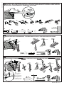
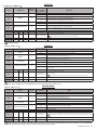
ASSEMBLAGGIO BINARIO - RAIL ASSEMBLY -ASSEMBLAGE RAIL - GLEISMONTAGE
ENSAMBLADO DEL RIEL - MONTAGE SPOOR
Binario unico
Single rail, RAIL unique
Einteiliges Gleis, Riel único,
Enkel spoor
Binario due pezzi
Two piece rail
Rail deux pièces
Zweiteiliges Gleis
Riel de dos piezas
Spoor twee delen
Catena, Chain, Chaîne
Kette, Cadena, Ketting
cinghia, belt, courroie
Riemen, correa, riem
DIMENSIONI - DIMENSIONS - DIMENSIONS -ABMESSUNGEN -
DIMENSIONES -
AFMETINGEN
* corsa utile/ usable travel /course utile / nutzhub/ carrera útil / werkslag
Nuove, new, nouveau
neu, nuevo, nieuw
Nuove, new, nouveau
neu, nuevo, nieuw vecchie, old, anciens
alt, viejo, oud
6 - BOTTICELLI BT AV 650
D814253 0AN00_01

Ø10
13 mm
D
Ø10 mm
Ø10 mm
Ø10 mm
*
*
**
*
*
*
*
E1
E2
60
6,3
Ø10 mm
Ø10 mm
F1
8
D1
60
8
V1
16
8
V2
V1
V2
V2
D1
F1
13
*
PH2
Ø10 mm
48 mm
Ø10 mm
PH2
Ø10 mm
==
PH2
13 mm
13
max
5,5 mm
FISSAGGIO STAFFA “PORTABINARIO” A SOFFITTO - FIXING OF THE CEILING “RAIL SUPPORT BRACKET” - FIXATION SUPPORT «
PORTE-RAIL » DE PLAFOND - BEFESTIGUNGSBÜGEL „GLEISTRÄGER” AN DER ABDECKUNG - FIJACIÓN DEL ESTRIBO “PORTA-RIEL”
EN EL TECHO - BEVESTIGING BEUGEL “SPOORDRAGER” AAN PLAFOND -
FISSAGGIO BINARIO A SOFFITTO - ASSEMBLY OF TRACK HOLDING BRACKET ONTO THE WALL - FIXATION RAIL AU PLAFOND
BEFESTIGUNG GLEIS AN DER ABDECKUNG - FIJACIÓN DEL RIEL EN EL TECHO - BEVESTIGING SPOOR AAN PLAFOND
FISSAGGIO BINARIO A SOFFITTO CON STAFFE -CEILING RAIL FIXING WITH BRACKETS- FIXATION RAIL DE PLAFOND AVEC SUPPORTS
BEFESTIGUNG GLEIS AN DER ABDECKUNG MIT BÜGELN - FIJACIÓN DEL RIEL EN TECHO CON ESTRIBOS -BEVESTIGING SPOOR AAN PLAFOND MET BEUGELS
Non in dotazione.
Not supplied.
Ne sont pas fournis.
Nicht im lieferum.
No asignadas en el
equipamiento base.
Niet meegeleverd.
BOTTICELLI BT AV 650 - 7
D814253 0AN00_01

30
8
V3
F
G
H
1
2
4
3
3
1
60
8
8
V1
V1
V1
V2
8
40
V2
V3
V3
D1
D1
D1
V2
2
V1
4,8
25 V2
3,5
25
2
V1
3
V2
3,9
13
V1 V2
25
4,8
13
PH2 PH1
PH1
PH2
6
Ø 5 mm
PH2
PH2
1
Ø5
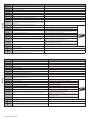
ASSEMBLAGGIO BRACCIO TRAINO - ASSEMBLY OF TRACK ONTO THE TRACK HOLDING BRACKET - ASSEMBLAGE BRAS ENTRAINEMENT
MONTAGE SCHLEPPARM - ENSAMBLADO DEL BRAZO DE ARRASTRE - MONTAGE SLEEPARM
MONTAGGIO TESTA A BINARIO - HEAD ASSEMBLY TO RAIL - MONTAGE TÊTE À RAIL -MONTAGE KOPF AN GLEIS
MONTAJE DEL CABEZAL AL RIEL - MONTAGE KOP OP SPOOR
INSTALLAZIONI PARTICOLARI CON TESTA RUOTATA - PARTICULAR INSTALLATIONS WITH ROTATED HEAD
INSTALLATIONS PARTICULIÈRES AVEC TÊTE TOURNÉE-BESONDERE INSTALLATIONEN MIT GESCHWENKTEM KOPF
INSTALACIONES ESPECIALES CON CABEZAL GIRADO-BIJZONDERE INSTALLATIES MET GEDRAAIDE KOP
Per installazioni della testa a 90°, montare la testa al binario prima di montare il binario al sotto.
For 90° head installations, mount the head to the rail before mounting the rail to the ceiling.
Pour les installations de la tête à 90°, monter la tête sur le rail avant de xer le rail au plafond.
Montieren Sie bei Installationen des Kopfes bei 90° den Kopf am Gleis, bevor Sie das Gleis an der.
Para instalar el cabezal a 90°, montar el cabezal al riel, antes de montar el riel en el techo.
Voor installaties van de kop op 90°, monteer de kop op het spoor alvorens het spoor op het plafond
te monteren.
8 - BOTTICELLI BT AV 650
D814253 0AN00_01

13
4,2
1
2
4
. . . . . .
. . . . . .
. . . . . .
. . . . . .
KO
>30 s
>30 s
>30 s
KO
KO
KO
OK
5 s
OK
3
H
I
fast
PH2
*
*
*
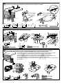
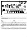
MESSA IN FUNZIONE CON COPERCHIO CHIUSO - START UP WITH COVER CLOSED
MISE EN SERVICE AVEC COUVERCLE FERMÉ-INBETRIEBNAHME MIT GESCHLOSSENEM DECKEL
PUESTA EN FUNCIONAMIENTO CON TAPA CERRADA
INBEDRIJFSTELLING MET DEKSEL GESLOTEN
Funzione attivata automaticamente solo se le impostazioni sono quelle di fabbrica (default) e nessun radiocomando memorizzato
ATTENZIONE!! Vericare che il valore della forza d’impatto misurato nei punti previsti dalla norma EN12445, sia inferiore a quanto indicato nella norma EN 12453.
Attenzione!! Durante l’autosettaggio la funzione di rilevamento ostacoli non è attiva, l’installatore deve controllare il movimento dell’automazione ed impedire a persone
o cose di avvicinarsi o sostare nel raggio di azione dell’automazione.
Function activated automatically only if the settings are the factory settings (default) and no remote control is memorized
WARNING!! Check that the force of impact measured at the points provided for by standard EN 12445 is lower than the value laid down by standard EN 12453.
Warning!! While the autoset function is running, the obstacle detection function is not active. Consequently, the installer must monitor the automated system’s
movements and keep people and property out of range of the automated system.
Fonction activée automatiquement uniquement si les réglages sont les réglages d’usine (par défaut) et sans télécommande mémorisée
ATTENTION !! Vériez si la valeur de la force de choc mesurée dans les points prévus par la norme EN12445 est inférieure à celle indiquée dans la norme EN 12453.
Attention !! Pendant l’autoréglage la fonction de détection des obstacles n’étant pas active le monteur doit contrôler le mouvement de l’automatisation et empêcher
que des personnes ou des choses ne s’approchent ou ne stationnent dans le rayon d’action de l’automatisation.
Die Funktion wird nur automatisch aktiviert, wenn die Werkseinstellungen (Default) eingestellt sind und keine Funksteuerung gespeichert ist
ACHTUNG!! Stellen Sie sicher, dass der Wert der Kraft, gemessen an den gemäß Norm EN12445 vorgesehenen Punkten, kleiner als der in der Norm EN 12453 angegeben ist.
Achtung!! Während der Auto-Einstellung ist die Funktion Hinderniserfassung nicht aktiv; der Monteur muss die Bewegung der Automatisierung überwachen und verhindern,
dass Personen oder Sachen in den Bewegungsbereich der Automatisierung gelangen.
La función se activa automáticamente solo si conserva las conguraciones de fábrica (default) y no hay ningún radiocontrol memorizado
¡ATENCIÓN! Controlar que el valor de la fuerza de impacto medido en los puntos previstos por la norma EN 12445 sea inferior al indicado en la norma EN 12453.
¡Atención! Durante la fase de conguración automática, la función de detección de obstáculos no está activada, por lo que el instalador debe controlar el movimiento
de la automatización e impedir que personas y cosas se acerquen o permanezcan en el radio de acción de la misma.
Functie enkel automatisch ingeschakeld als de (standaard) fabrieksinstellingen actief zijn en er geen afstandsbediening opgeslagen is
OPGELET!! Controleren of de waarde van de botsingskracht gemeten in de punten voorzien door de norm EN12445, lager is dan hetgeen aangegeven in de norm EN 12453.
Opgelet!! Tijdens de autoset-fase is de functie voor obstakeldetectie niet actief; de installateur moet de beweging van het automatiseringssysteem controleren en
voorkomen dat personen of voorwerpen in de buurt komen van de actieradius van het automatiseringssysteem of zich daarbinnen bevinden.
* in dotazione con il binario - supplied with the rail - fourni avec le rail
mit dem Gleis mitgeliefert - en dotación con el riel - meegeleverd met het spoor
BOTTICELLI BT AV 650 - 9
D814253 0AN00_01

H
L
24V
2
1TX1 2
1
RX1
4
5
3
50 51
70 73
24V
2
1TX1 2
1
RX1
4
5
3
50 51 52
70 73
D3=ON
D3=OFF
(1TX + 1RX)
(1TX + 1RX)
-
+
VSafe+
IC 1
IC 2
NO
NO
SAFE 1
STOP
COM
SAFE 2
NC
NC
NC
*
*
73 72 71
62 61 51 27 26
60
70
52
21
50
20
Fig. L2
24V
0V
70 72
D2=OFF
D2=ON
50 51 52
5
6
3
2
1
51
50
70
72
51
4
70
72
8,2Kohm 5%
SAFETY EDGE SAFETY EDGE
BAR
70 72
Fig. L1
24 VDC max 5W
24VDC
max 300 mA
51
52
21
50
20
Luce di cortesia, Courtesy lamp,
Lampe de courtoisie,
Hilfsbeleuchtung, Luz interior,
Waaklicht.
Connettore programmatore palmare,
Palmtop programmer connector,
Connecteur programmateur de poche,
Steckverbinder Palmtop-Programmierer,
Conector del programador de bolsillo,
Connector programmeerbare palmtop.
Display + tasti programmazione,
Display plus programming keys,
Acheur et touches de programmation,
Display und Programmierungstasten,
Pantalla más botones de programación,
Display meerdere toetsen programmeur.
Non utilizzato
Not used
Non utilisé
Nicht verwendet
No utilizado
Niet in gebruik
Alimentazione in corrente continua
Direct current supply
Alimentation en courant continu
Gleichstromversorgung
Alimentación de corriente continua
Gelijkstroomvoeding
Solo lampeggiante a LED - LED ashing only
LED clignotante uniquement - Nur LED Blinklicht
Solo luz LED intermitente - Enkel LED-knipperlicht
10 - BOTTICELLI BT AV 650
D814253 0AN00_01

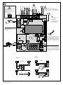
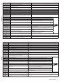
ITALIANO
Morsetto Denizione Descrizione
Alimen-
tazione
JP2 SEC TRASF Alimentazione scheda:
24V~ Secondario trasformatore
Motore
JP7 MOT+ENC Collegamento motore ed encoder
Aux
20 LAMPEGGIANTE
CONTATTO ALIMENTATO
24V (N.O.) (1A MAX)
Uscita LAMPEGGIANTE.
24 VDC MAX 5W (usare lampeggiante a LED)
21
26 NON UTILIZZATO
27
Alim.
Accessori
50 - Uscita alimentazione accessori.
24VDC (Alimentazione in corrente continua)
51 +
52 Vsafe+
Uscita alimentazione per dispositivi di sicurezza vericati (trasmettitore fotocellule).
Uscita attiva solo durante il ciclo di manovra.
Comandi
60 Comune Comune ingressi IC 1 e IC 2 FUNZIONAMENTO 4 PASSI
CHIUSA APRE
IN
CHIUSURA
STOP
APERTA CHIUDE
IN
APERTURA STOP + TCA
DOPO STOP
APRE
61 IC 1 Ingresso di comando (N.O.) START.
Funzionamento secondo la Logica 4 passi..
62 IC 2 Ingresso di comando (N.O.) PED.
Il comando esegue un’apertura pedonale, parziale. Funzionamento secondo la
Logica 4 passi.
Sicurezze
70 Comune Comune ingressi STOP, SAFE 1 e SAFE 2
71 STOP Il comando interrompe la manovra. (N.C.)
Se non si utilizza lasciare il ponticello inserito.
72 SAFE 1
Ingresso di sicurezza congurabile 1 (N.C.) - Default BAR.
d2=OFF-->BAR
Consente la connessione di dispositivi non dotati di contatto supplementare di verica. Il comando inverte il movimento per 2 sec.
Se non si utilizza lasciare il ponticello inserito.
d2=On-->BAR 8K2
Ingresso per bordo resistivo 8K2.
Il comando inverte il movimento per 2 sec.
73 SAFE 2
Ingresso di sicurezza congurabile 2 (N.C.) - Default PHOT.
d3=OFF-->PHOT
Consente la connessione di dispositivi non dotati di contatto supplementare di verica. In caso di oscuramento, le fotocellule
sono attive sia in apertura che in chiusura. Un oscuramento della fotocellula in chiusura, inverte il moto solo dopo il disimpegno
della fotocellula. Se non si utilizza lasciare il ponticello inserito.
d3=On-->PHOT TEST
Attiva la verica delle fotocellule ad inizio manovra. In caso di oscuramento, le fotocellule sono attive sia in apertura che in chiusura.
Un oscuramento della fotocellula in chiusura, inverte il moto solo dopo il disimpegno della fotocellula.
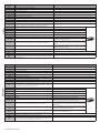
ENGLISH
Terminal Denition Description
Power
supply
JP2 TRANSF SEC Board power supply:
24V~ Transformer secondary winding
Motor
JP7 MOT + ENC Connection motor and encoder
Aux
20 FLASHING LIGHT - 24V POWERED
CONTACT (N.O.) (MAX. 1A)
AUX 0 congurable output - Default setting FLASHING LIGHT.
24 VDC MAX 5W (use LED ashing)
21
26 NOT USED
27
Accessories
power
supply
50 - Accessories power supply output.
24 VDC (direct current supply)
51 +
52 Vsafe+ Tested safety device power supply output (photocell transmitter).
Output active only during operating cycle.
Commands
60 Common IC 1 and IC 2 inputs common Operation 4 step
CLOSED opens
DURING CLOSING stop
OPEN closes
DURING OPENING stop + TCA
AFTER STOP opens
61 IC 1 Command input (N.O.) - START .
Operation according to 4-step logic.
62 IC 2 Command input (N.O.) - PED.
The command causes the leaf to open to the pedestrian (partial) opening
position. Operation according to 4-step logic.
Safety devices
70 Common STOP, SAFE 1 and SAFE 2 inputs common
71 STOP The command stops movement. (N.C.)
If not used, leave jumper inserted.
72 SAFE 1
Input for safety devices congurable 2 (N.C.) - Default BAR.
d2=OFF-->BAR
Enables connection of devices not equipped with supplementary test contacts. The command reverses movement
for 2 sec.. If not used, leave jumper inserted.
d2=On-->BAR 8K2
Input for resistive edge 8K2.
The command reverses movement for 2 sec.
73 SAFE 2
Input for safety devices congurable 2 (N.C.) - Default PHOT.
d3=OFF-->PHOT
Enables connection of devices not equipped with supplementary test contacts. When beam is broken, photocells are
active during both opening and closing. When beam is broken during closing, movement is reversed only once the
photocell is cleared. If not used, leave jumper inserted.
d3=On-->PHOT TEST
Switches photocell testing on at start of operation. When beam is broken, photocells are active during both opening
and closing. When beam is broken during closing, movement is reversed only once the photocell is cleared.
BOTTICELLI BT AV 650 - 11
D814253 0AN00_01

FRANÇAIS
Borne Dénition Description
Alimen-
tation
JP2 SEC TRANSF Alimentation de la carte:
24V~Secondaire transformateur
Moteur
JP7 MOT + ENC Connexion moteur et encoder
Aux
20 CLIGNOTANT - CONTATTO ALIMEN-
TATO 24V (N.O.) (1A MAX)
Sortie CLIGNOTANT
24 VCC MAX. 5 W (utiliser une LED clignotante)
21
26 NON UTILISÉ
27
Alimentation
des
accessoires
50 -Sortie alimentation accessoires.
24 VCC (alimentation en courant continu)
51 +
52 Vsafe+ Sortie alimentation des dispositifs de sécurité vériés (émetteur photocellules et émetteur linteau sensible)
Sortie active uniquement pendant le cycle de manœuvre.
Commandes
60 Commun Commun entrées IC 1 et IC 2 Fonctionnement 4 PAS
FERMÉE OUVRE
EN FERMETURE
STOP
OUVERTE FERME
EN OUVERTURE
STOP + TCA
APRÈS STOP
OUVRE
61 IC 1 Entrée de commande (N.O.) - START
Fonctionnement suivant la Logique 4 PAS
62 IC 2 Entrée de commande (N.O.) - PED.
La commande accomplit une ouverture piétonne, partielle.
Fonctionnement suivant la logique 4 PAS.
Sécurités
70 Commun Commun entrées STOP, SAFE 1 et SAFE 2
71 STOP La commande interrompt la manœuvre. (N.F.)
Si vous ne l’utilisez pas, laissez la barrette en place.
72 SAFE 1
Entrée de sécurité congurable 1 (N.F.) - Défaut BAR.
d2=OFF-->BAR
Permet de connecter les dispositifs dépourvus de contact supplémentaire de vérication. La commande inverse le
mouvement pendant 2s. Si vous ne l’utilisez pas, laissez la barrette en place
d2=On-->BAR 8K2
Entrée pour linteau résistif 8K2.
La commande inverse le mouvement pendant 2 secondes.
73 SAFE 2
Entrée de sécurité congurable 2 (N.F.) - Défaut PHOT.
d3=OFF-->PHOT
Permet de connecter les dispositifs dépourvus de contact supplémentaire de vérication. En cas d’obscurcissement,
les photocellules sont actives en ouverture et en fermeture. Un obscurcissement de la photocellule en fermeture
n’inverse le mouvement que lorsque la photocellule est libérée. Si vous ne l’utilisez pas, laissez la barrette en place.
d3=On-->PHOT TEST
Active la vérication des photocellules au début de la manoeuvre. En cas d’obscurcissement, les photocellules sont
actives en ouverture et en fermeture. Un obscurcissement de la photocellule en fermeture inverse le mouvement
uniquement après le dégagement de la photocellule.
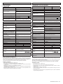
DEUTSCH
Klemme Denition Beschreibung
Strom-
versor-
gung
JP2 SEK TRASF Stromversorgungsdatenblatt:
24V~ Sekundärer Transformator
Motor
JP7 MOT+ENC Motor- und Encoderanschluss
Aux
20 BLINKEND - GESPEISTER KON-
TAKT 24V (N.O.) (1A MAX)
BLINKENDER Ausgang.
24 VDC MAX 5W (LED-Blinklicht verwenden)
21
26 NICHT VERWENDET
27
Stromvers.
Zubehör
50 - Ausgang Stromversorgung Zubehör.
24VDC (Gleichstromversorgung)
51 +
52 Vsafe+
Stromversorgungsausgang für geprüfte Sicherheitsvorrichtungen (Fotozellensender).
Ausgang nur während des Manöverzyklus aktiv
Befehle
60 Sammel Sammeleingänge IC 1 und IC 2 Bestimmungen 4SCHRITT
GESCHLOSSEN ÖFFNUNG
BEI SCHLIESSUNG
STOPP
OFFEN SCHLIESSUNG
BEI ÖFFNUNG
STOPP+ TCA
NACH STOP
ÖFFNUNG
61 IC 1 Befehlseingabe (N.O.) START.
Funktionsweise gemäß der 4-Schritt-Logik..
62 IC 2 Befehlseingabe (N.O.) PED.
Der Befehl führt eine teilweise Önung für Fußgänger durch.
Funktionsweise gemäß der 4-Schritt-Logik.
Sicherheit
70 Sammel Sammeleingänge STOP, SAFE 1 und SAFE 2
71 STOP Der Befehl unterbricht das Manöver. (N.C.)
Wenn nicht verwendet, die Überbrückung eingeschaltet lassen.
72 SAFE 1
Kongurierbarer Sicherheitseingang 1 (N.C.) - Default BAR.
d2=OFF-->BAR
Erlaubt den Anschluss von Vorrichtungen ohne zusätzlichen Prüfkontakt. Der Befehl kehrt die Bewegung für 2 Sek. um.
Wenn nicht verwendet, die Überbrückung eingeschaltet lassen.
d2=On-->BAR 8K2
Eingang für Widerstandsrahmen 8K2.
Der Befehl kehrt die Bewegung für 2 Sek. um.
73 SAFE 2
Kongurierbarer Sicherheitseingang 2 (N.C.) - Default PHOT.
d3=OFF-->PHOT
Erlaubt den Anschluss von Vorrichtungen ohne zusätzlichen Prüfkontakt. Bei einer Abdunklung sind die Fotozellen
sowohl beim Önen als auch beim Schließen aktiv. Eine Abdunklung der sich schließenden Fotozelle kehrt die
Bewegung nur um, nachdem die Fotozelle gelöst wurde. Wenn nicht verwendet, die Überbrückung eingeschaltet
lassen.
d3=On-->PHOT TEST
Aktivieren Sie die Überprüfung der Fotozellen zu Beginn des Manövers. Bei einer Abdunklung sind die Fotozellen
sowohl beim Önen als auch beim Schließen aktiv. Eine Abdunklung der sich schließenden Fotozelle kehrt die
Bewegung nur um, nachdem die Fotozelle gelöst wurde.
12 - BOTTICELLI BT AV 650
D814253 0AN00_01

ESPAÑOL
Terminal Denición Descripción
Alimen-
tación
JP2 SEC TRASF Alimentación tarjeta:
24 V~ Secundario transformador
Motor
JP7 MOT+ENC Conexión motor y encoder
Aux
20 INTERMITENTE - CONTACTO ALI-
MENTADO 24 V (N.A.) (1 A MÁX)
Salida INTERMITENTE.
24 VCC MAX 5W (usar luz LED intermitente)
21
26 NO UTILIZADO
27
Alim.
Accesorios
50 - Salida alimentación de los accesorios.
24VCC (alimentación de corriente continua)
51 +
52 Vsafe+
Salida alimentación para dispositivos de seguridad vericados (transmisor de células fotoeléctricas).
Salida activa solo durante el ciclo de maniobra.
Mandos
60 Común Común entradas IC 1 e IC 2 FUNCIONAMIENTO 4 PASOS
CERRADA ABRE
EN FASE DE CIERRE
STOP
ABIERTA CIERRA
EN FASE DE APERTURA STOP + TCA
DESPUÉS DE STOP
ABRE
61 IC 1 Entrada del mando (N.A.) START.
Funcionamiento según la lógica 4 pasos.
62 IC 2 Entrada del mando (N.A.) PED.
El comando ejecuta una apertura peatonal parcial. Funcionamiento
según la lógica 4 pasos.
Medidas de seguridad
70 Común Común entradas STOP, SAFE 1 y SAFE 2
71 STOP El mando interrumpe la maniobra. (N.C.)
Si no se utiliza, dejar el puente conectado.
72 SAFE 1
Entrada de seguridad congurable 1 (N.C.) - Default BAR.
d2=OFF-->BAR
Permite conectar dispositivos que no tienen el contacto adicional de control. El mando invierte el movimiento durante 2
segundos. Si no se utiliza, dejar el puente conectado.
d2=On-->BAR 8K2
Entrada para borde resistivo 8K2.
El mando invierte el movimiento durante 2 segundos.
73 SAFE 2
Entrada de seguridad congurable 2 (N.C.) - Default PHOT.
d3=OFF-->PHOT
Permite conectar dispositivos que no tienen el contacto adicional de control. En caso de interrupción, se activan las
células fotoeléctricas tanto en apertura como en cierre. Si se interrumpe la célula fotoeléctrica durante el cierre, solo
invierte el movimiento cuando se libera la célula fotoeléctrica. Si no se utiliza, dejar el puente conectado.
d3=On-->PHOT TEST
NEDERLANDS
Klem Denitie Beschrijving
Voe-
ding
JP2 SEC TRASF Toevoer kaart:
24V~ Secundaire transformator
Motor
JP7 MOT+ENC Verbinding motor en encoder
Aux
20 KNIPPERLICHT - CONTACT GEVO-
ED 24V (N.O.) (1A MAX)
Uitgang KNIPPERLICHT.
24 VDC MAX 5W (gebruik LED-knipperlicht)
21
26 NIET GEBRUIKT
27
Toev.
Accessoires
50 - Uitgang toevoer accessoires.
24VDC (Gelijkstroomvoeding)
51 +
52 Vsafe+
Uitgang voeding voor geverieerde veiligheidsvoorzieningen (zender fotocellen).
Uitgang enkel actief tijdens de bewegingscyclus.
Bbedieningen
60 Gemeenschappelijk Gemeenschappelijk ingangen IC 1 en IC 2 WERKING 4-STAPS
GESLOTEN OPENT
BIJ SLUITING
STOP
OPEN SLUIT
BIJ OPENING STOP + TCA
NA STOP
OPENT
61 IC 1 Ingang commando (N.O.) START.
Werking volgens Logica 4 stappen.
62 IC 2 Ingang commando (N.O.) VOET.
Het commando voert een gedeeltelijke voetgangersopening uit.
Werking volgens Logica 4 stappen.
Beveiligingen
70 Gemeenschappelijk Gemeenschappelijk ingangen STOP, SAFE 1 en SAFE 2
71 STOP Het commando onderbreekt de beweging. (N.C.)
Laat de brug verbonden indien ze niet gebruikt wordt.
72 SAFE 1
Congureerbare veiligheidsingang 1 (N.C.) - Default BAR.
d2=OFF-->BAR
Staat de aansluiting toe van apparaten die niet voorzien zijn van bijkomende controlecontact. De bediening keert de
beweging voor 2 sec om. Laat de brug verbonden indien ze niet gebruikt wordt.
d2=On-->BAR 8K2
Ingang voor resistieve rand 8K2.
De bediening keert de beweging voor 2 sec om.
73 SAFE 2
Congureerbare veiligheidsingang 2 (N.C.) - Default PHOT.
d3=OFF-->PHOT
Staat de aansluiting toe van apparaten die niet voorzien zijn van bijkomende controlecontact. In geval van verduistering,
zijn de fotocellen actief zowel bij opening als bij sluiting. Een verdonkering van de fotocel tijdens de sluiting, keert de
beweging pas na vrijgave van de fotocel om. Laat de brug verbonden indien ze niet gebruikt wordt.
d3=On-->PHOT TEST
Hiermee activeert u de controle van de fotocellen aan het begin van de beweging. In geval van verduistering, zijn de
fotocellen actief zowel bij opening als bij sluiting. Een verdonkering van de fotocel tijdens de sluiting, keert de beweging
keert pas na vrijgave van de fotocel om.
BOTTICELLI BT AV 650 - 13
D814253 0AN00_01

H
M
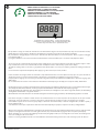
888.8
MODALITÀ BASSO CONSUMO D4 E ACCESSORI
LOW POWER MODE D4 AND ACCESSORIES
MODE BASSE CONSOMMATION D4 ET ACCESSOIRES
ENERGIESPARMODUS D4 UND ZUBEHÖR
MODO DE BAJO CONSUMO D4 Y ACCESORIOS
SPAARSTAND D4 EN ACCESSOIRES
modalità basso consumo attiva - active low power mode
mode basse consommation actif - Energiesparmodus aktiv
modo de bajo consumo activo - spaarstand actief
Per risparmiare energia, la centrale di comando stacca l’alimentazione degli accessori (morsetti 50-51) dopo 10s che il motore è fermo,
quindi tutti gli accessori vengono disattivati, la modalità basso consumo viene indicata da un punto sul display.
Per permettere il settaggio degli accessori (ad es. allineamento delle fotocellule) è necessario impostare d4=0, eseguire il settaggio
e poi impostare d4=1
Se vengono utilizzati accessori che richiedono un’alimentazione senza interruzioni (ad es. ricevitori radio) impostare d4=0
To save energy, the control unit disconnects the power supply of the accessories (terminals 50-51) after 10s that the engine is statio-
nary and then all accessories are switched o; the low consumption mode is indicated by a point on the display.
To allow the setting of the accessories (e.g. alignment of the photocells) it is necessary to set d4=0; perform the setting and then set
d4=1
If accessories that require uninterrupted power supply (e.g. radio receivers) are used, set d4=0
Pour économiser de l’énergie, l’unité de commande coupe l’alimentation des accessoires (bornes 50-51) après 10 s que le moteur est
arrêté, puis tous les accessoires sont désactivés, le mode basse consommation est indiqué par un point sur l’écran.
Pour permettre le réglage des accessoires (par exemple, l’alignement des photocellules), il faut dénir d4=0, eectuer le réglage, puis
dénir d4=1
En cas d’utilisation d’accessoires nécessitant une alimentation ininterrompue (par exemple, des récepteurs radio), dénir d4=0
Um Energie zu sparen, trennt die Steuereinheit die Stromversorgung des Zubehörs (Klemmen 50-51) 10s nachdem der Motor stoppt,
dann wird jedes Zubehör deaktiviert, der Energiesparmodus wird durch einen Punkt auf dem Display angezeigt.
Um die Einstellung des Zubehörs (z. B. Ausrichtung der Fotozellen) zu ermöglichen, muss d4=0 eingestellt werden, die Einstellung
durchgeführt und dann d4=1 eingestellt werden
Wenn Zubehör verwendet wird, das eine unterbrechungsfreie Stromversorgung erfordert (z. B. Funkempfänger), d4=0 einstellen
Para ahorrar energía, la central de control desconecta la alimentación de los accesorios (bornes 50-51) después de 10s que el motor
está parado, por lo que todos los accesorios se desactivan, el modo de bajo consumo se indica con un punto en la pantalla.
Para habilitar el ajuste de los accesorios (por ejemplo, la alineación de las fotocélulas) se deberá congurar d4=0, realizar el ajuste y
luego congurar d4=1
Si se utilizan accesorios que requieren una alimentación ininterrumpida (por ejemplo, receptores de radio), congurar d4=0
Om energie te besparen onderbreekt de regeleenheid de stroomtoevoer naar het toebehoren (klemmen 50-51) 10s nadat de motor
gestopt is, vervolgens worden alle accessoires gedeactiveerd, de spaarstand wordt aangegeven door een punt op het display.
Om de instelling van accessoires (bv. uitlijning van fotocellen) mogelijk te maken, is het nodig d4=0 in te stellen, de instelling uit te
voeren en vervolgens d4=1 in te stellen
Indien accessoires gebruikt worden die een ononderbroken stroomvoorziening vereisen (b.v. radio-ontvangers), stel dan d4=0 in
14 - BOTTICELLI BT AV 650
D814253 0AN00_01

N
5s
auto . . . . . .
4
. . . . . .
KO
. . . . . .
fast
fast
13
4,2
1
2
OK
3
PH2
*
*
*
*in dotazione con il binario - supplied with the rail - fourni avec le rail
mit dem Gleis mitgeliefert - en dotación con el riel - meegeleverd met het spoor
ATTENZIONE!! Vericare che il valore della forza d’impatto misurato nei punti previsti dalla norma EN12445, sia inferiore a quanto
indicato nella norma EN 12453.
Attenzione!! Durante l’autosettaggio la funzione di rilevamento ostacoli non è attiva, l’installatore deve controllare il movimento
dell’automazione ed impedire a persone o cose di avvicinarsi o sostare nel raggio di azione dell’automazione.
WARNING!! Check that the force of impact measured at the points provided for by standard EN 12445 is lower than the value laid
down by standard EN 12453.
Warning!! While the autoset function is running, the obstacle detection function is not active. Consequently, the installer must monitor
the automated system’s movements and keep people and property out of range of the automated system.
ATTENTION !! Vériez si la valeur de la force de choc mesurée dans les points prévus par la norme EN12445 est inférieure à celle
indiquée dans la norme EN 12453.
Attention !! Pendant l’autoréglage la fonction de détection des obstacles n’étant pas active le monteur doit contrôler le mouvement
de l’automatisation et empêcher que des personnes ou des choses ne s’approchent ou ne stationnent dans le rayon d’action de l’auto-
matisation.
ACHTUNG!! Stellen Sie sicher, dass der Wert der Kraft, gemessen an den gemäß Norm EN12445 vorgesehenen Punkten, kleiner als
der in der Norm EN 12453 angegeben ist.
Achtung!! Während der Auto-Einstellung ist die Funktion Hinderniserfassung nicht aktiv; der Monteur muss die Bewegung der Auto-
matisierung überwachen und verhindern, dass Personen oder Sachen in den Bewegungsbereich der Automatisierung gelangen.
¡ATENCIÓN! Controlar que el valor de la fuerza de impacto medido en los puntos previstos por la norma EN 12445 sea inferior al indicado
en la norma EN 12453.
¡Atención! Durante la fase de conguración automática, la función de detección de obstáculos no está activada, por lo que el instalador
debe controlar el movimiento de la automatización e impedir que personas y cosas se acerquen o permanezcan en el radio de acción
de la misma.
OPGELET!! Controleren of de waarde van de botsingskracht gemeten in de punten voorzien door de norm EN12445, lager is
dan hetgeen aangegeven in de norm EN 12453.
Opgelet!! Tijdens de autoset-fase is de functie voor obstakeldetectie niet actief; de installateur moet de beweging van het automatise-
ringssysteem controleren en voorkomen dat personen of voorwerpen in de buurt komen van de actieradius van het automatiserings-
systeem of zich daarbinnen bevinden.
MESSA IN FUNZIONE - START-UP - MISE EN SERVICE - INBETRIEBNAHME
PUESTA EN FUNCIONAMIENTO - INBEDRIJFSTELLING
H
M
888.8
BOTTICELLI BT AV 650 - 15
D814253 0AN00_01

H
Q
H
P
H
O
2s
o o o
<10 s
5s
prg
<10 s
2s
o o o
<10 s <10 s
1 2 3 4 5 6 7
10 s 10 s
o o
o o
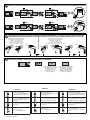
PROGRAMMAZIONE TRASMETTITORI MANUALE - MANUAL TRANSMITTER PROGRAMMING -PROGRAMMATION MANUELLE ÉMETTEURS-
MANUELLE SENDERPROGRAMMIERUNG-PROGRAMACIÓN MANUAL DE LOS TRANSMISORES-HANDMATIGE PROGRAMMERING ZENDERS
CANCELLAZIONE TRASMETTITORI TRANSMITTERS CANCELLATION ANNULATION DES ÉMETTEURS
LÖSCHEN DER SENDER-ELIMINACIÓN TRANSMISORES-WISSEN ZENDERS
PROGRAMMAZIONE TRASMETTITORI REMOTA REMOTE TRANSMITTER PROGRAMMING PROGRAMMATION ÉMETTEURS À DISTANCE FERN
PROGRAMMIERUNG DER SENDER-ROGRAMACIÓN A DISTANCIA DE LOS TRANSMISORES-PROGRAMMERING ZENDERS OP AFSTAND
-
--
trasemttitore già memorizzato
transmitter already memorized
émetteur déjà mémorisé
Sender bereits gespeichert
Transmisor ya memorizado
Reeds opgeslagen zender
trasemttitore da memorizzare
transmitter to be memorized
Émetteur à mémoriser
Sender zu speichern
Transmisor para memorizar
Zender die opgeslagen moet worden
Cancellazione in corso
Cancellation in progress
Annulation en cours
Löschen läuft
Eliminación en curso
Wissen bezig
Cancellazione eettuata
Cancellation completed
Annulation eectuée
Löschen durchgeführt
Eliminación efectuada
Wissen uitgevoerd
ITALIANO
• Comando apertura
• ≥ 2 sec Programmazione tra-
smettitore manuale come start
• Comando chiusura
•
≥ 2 sec Programmazione tra-
smettitore manuale come 2° ca-
nale radio
• ≥ 5 sec Cancellazione radio-
comandi
• Accesso al menù
• ≥ 5 sec menù autoset
ENGLISH
• Opening command
• ≥ 2 sec Manual transmitter pro-
gramming as start
• Closure command
• ≥ 2 sec Manual transmitter pro-
gramming as 2nd radio channel
• ≥ 5 sec Cancellation of remo-
te controls
• Access menu
• ≥ 5 sec menu autoset
FRANÇAIS
• Commande ouverture
• ≥ 2 sec Programmation manuel-
le émetteur comme démarrage
• Commande fermeture
• ≥ 2 sec Programmation manuelle
émetteur comme 2e canal radio
• ≥ 5 sec Suppression radio-
commandes
• Accès au menu
• ≥ 5 sec menu auto-congu-
ration
16 - BOTTICELLI BT AV 650
D814253 0AN00_01

. . . . . . . .
5 s.
LEGENDA
H
R
MENU
Parametro
Parameter
Paramètre
Parameter
Parámetro
Parameter
Accensione display/conferma
Switch on display/Conrm
Allumage acheur / conrmation
Displayeinschaltung / Bestätigung
Encendido pantalla/Conrmación
Inschakeling display / bevestiging
Uscita menù
Exit Menu
Sortir du menu
Menüausgang
Salida menú
Uitgang menu
incremento
increased
augmentation
Erhöhung
incremento
vergroting
decremento
decreased
diminution
Absenkung
decremento
daling
Valore
Value
Valeur
Valore
Value
Valeur
Versione software centrale
Control unit software version
Version logiciel centrale
Zentrale Softwareversion
Versión software central
Centrale softwareversie
DEUTSCH
• Önungsbefehl
• ≥ 2 Sek Manuelle Sender-
programmierung wie Start
• Schließbefehl
• ≥ 2 Sek Manuelle Sender-
programmierung wie 2. Ra-
diokanal
• ≥ 5 Sek Löschung Funk-
steuerungen
• Zugang zum Menü
•
≥ 5 Sek Autoeinstellungsmenü
NEDERLANDS
• Commando opening
•
≥ 2 sec Programmering
handmatige zender als start
• Commando sluiting
• ≥ 2 sec Programmering
handmatige zender als 2°
radiokanaal
• ≥ 5 sec Wissen afstandsbe-
dieningen
• Toegang tot menu
• ≥ 5 sec menu autoset
ESPAÑOL
• Mando de apertura
•
≥ 2 seg. Programación manual
del transmisor como start
• Mando de cierre
• ≥ 2 seg. Programación
manual del transmisor como
2° canal radio
• ≥ 5 seg. Eliminación de los
radiocontroles
• Acceso al menú
• ≥ 5 seg. Menú autoset
Wert
Valor
Waarde
Wert
Valor
Waarde
BOTTICELLI BT AV 650 - 17
D814253 0AN00_01

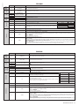
ITALIANO
TABELLA “A” - MENU PARAMETRI - (para )
Logica Denizione
Default
Barrare
il
settaggio
eseguito
Opzioni
d1 Blocca Impulsi apertura OFF ON L’impulso di start non ha alcun eetto durante la fase di apertura.
OFF L’impulso di start ha eetto durante la fase di apertura.
d2 BAR/8K2 OFF
ON Ingresso congurato come Bar 8k2. Ingresso per bordo resistivo 8K2 (Fig. L1).
Il comando inverte il movimento per 2 sec.
OFF Ingresso congurato come Bar, costa sensibile.
Il comando inverte il movimento per 2 sec.
d3 Test fotocellule OFF ON Attiva la verica delle fotocellule (Fig. L2)
OFF Disattiva la verica delle fotocellule
d4 Attivazione Power Down ON
ON Power Down ATTIVO, cioè l’alimentazione degli accessori (morsetti 50-51) viene disattivata a
cancello fermo. (Vedi Fig.M)
OFF Power Down DISATTIVO, cioè l’alimentazione degli accessori (morsetti 50-51) è sempre presente.
(Vedi Fig. M)
Parametro Min. Max.
Default
Personali
Denizione Descrizione
T1 0 99 0 Tempo chiusura
automatica [%]
0= chiusura automatica disabilitata
1-99= imposta il valore del tempo di chiusura automatica tra 1% e 99% (corrisponde a 1s - 180s)
E’ obbligatorio installare una coppia di fotocellule se si abilita il funzionamento automatico
T2 1 99 75
Coppia apertura [%]
Impostare il valore di coppia di apertura del motore tra 1% e 99%. *
T3 1 99 75
Coppia chiusura [%]
Impostare il valore di coppia di chiusura del motore tra 1% e 99%.
*
*
ATTENZIONE: Vericare che il valore della forza d’impatto misurato nei punti previsti dalla norma EN12445, sia inferiore a quanto indicato nella norma EN 12453.
Una errata impostazione della sensibilità può creare danni a persone, animali o cose.
ENGLISH
TABLE “A” PARAMETERS MENU - PARA
LOGIC Denition Default
Tick the setting made
Options
d1 Opening impulse block OFF ON The start impulse has no eect during the opening phase.
OFF The start impulse has eect during the opening phase.
d2 BAR/8K2 OFF
ON Input congured as Bar 8k2. Input for resistive edge 8K2 (Fig. L1).
The command reverses movement for 2 sec.
OFF Input congured as Bar, safety edge.
The command reverses movement for 2 sec.
d3 Photocell Test OFF ON Activates the photocell control (Fig. L2)
OFF
Deactivates the photocell control
d4 Power Down
activation ON
ON Power Down ACTIVE, i.e. the power supply of the accessories (terminals 50-51) is deactivated
when the gate is stopped. (See Fig.M)
OFF Power Down OFF, i.e. the power supply of the accessories (terminals 50-51) is always present.
(See Fig. M)
Parameter Min. Max. Default
Personal
Denition DESCRIPTION
t1 0 99 0 Automatic closure
time [%]
0= Automatic closure disabled
1-99= sets the value of the automatic closure time between 1% and 99% (corresponds to 1s - 180s)
A pair of photocells must be installed if the automatic operation is enabled
t2 1 99 50 Opening torque [%]
Set the motor opening torque value between 1% and 99%. *
t3 1 99 50 Closure torque [%] Set the motor closure torque value between 1% and 99%. *
WARNING: Check that the impact force value measured at the points foreseen by the EN12445 standard, is lower than that indicated in the EN 12453 standard.
Incorrect sensitivity setting can cause injury and damage people, animals or property.
FRANÇAIS
TABLEAU “A” - MENU PARAMÈTRES - (para )
Logique Dénition Défaut Cochez le réglage
accompli Options
d1 Verrouille Impulsions
ouverture OFF ON L’impulsion de démarrage n’a aucun eet pendant la phase d’ouverture..
OFF L’impulsion de démarrage a eet pendant la phase d’ouverture.
d2 BAR/8K2 OFF
ON
Entrée congurée comme Bar 8k2. Entrée pour linteau résistif 8K2
(Fig. L1)
.
La commande invertit le mouvement pendant 2 secondes.
OFF
Entrée congurée comme Bar, linteau sensible.
La commande invertit le mouvement pendant 2 secondes.
d3 Essai photocellules OFF ON Active la vérication des photocellules (Fig. L2)
OFF Désactive la vérication des photocellules.
d4 Activation de Power
Down ON
ON Power Down ACTIVÉ, c’est-à-dire que l’alimentation des accessoires (bornes 50-51) est désactivée
lorsque le portail est à l’arrêt. (Voir g. M)
OFF Power Down DÉSACTIVÉ, c’est-à-dire que l’alimentation des accessoires (bornes 50-51) est toujours
présente. (Voir g. M)
Paramètre mini maxi Défaut
Personnels
Dénition Description
t1 0 99 0 Temps de
Fermeture
Automatique [%]
0= fermeture automatique désactivée
1-99= congure la valeur de la durée de la fermeture automatique entre 1% et 99% (correspond
à 1s - 180s)
Installer impérativement une paire de cellules photoélectriques en cas d’activation du
fonctionnement automatique
t2 1 99 50
Couple ou verture [%]
Congurez la valeur de couple d’ouverture du moteur entre 1% et 99%
*
t3 1 99 50 Couple fermeture [%] Congurez la valeur de couple de fermeture du moteur entre 1% et 99%*
*
ATTENTION: Vériez si la valeur de la force d’impact mesurée dans les points prévus par la norme EN12445 est inférieure à celle indiquée dans la norme EN12453.
Toute erreur de conguration de la sensibilité peut causer des préjudices aux personnes, aux animaux et aux biens.
18 - BOTTICELLI BT AV 650
D814253 0AN00_01

DEUTSCH
TABELLE „A” - MENÜ(para )
Logik Denition Vorein-
stellung
Kreuzen Sie die
ausgeführte
Einstellung an
Optionen
d1 Önung Impulsblockierung OFF ON Der Startimpuls hat während der Önungsphase keine Wirkung.
OFF Der Startimpuls hat Wirkung während der Önungsphase.
d2 BAR/8K2 OFF
ON Als Bar 8k2 kongurierter Eingang. Eingang für Widerstandskante 8K2 (Fig. L1)
Der Befehl kehrt die Bewegung für zwei Sekunden um.
OFF Als Bar kongurierter Eingang, Tastleiste.
Der Befehl kehrt die Bewegung für zwei Sekunden um.
d3 Test Fotozellen OFF ON Aktivieren Sie die Überprüfung der Fotozellen (Fig. L2)
OFF
Deaktivieren Sie die Überprüfung der Fotozellen
d4 Aktivierung Power Down ON
ON Power Down AKTIVIERT, d.h. die Stromversorgung des Zubehörs (Klemmen 50-51) wird deakti-
viert, wenn das Tor angehalten wird. (Siehe Abb. M)
OFF Power Down DEAKTIVIERT, d.h. die Stromversorgung des Zubehörs (Klemmen 50-51) ist immer
vorhanden. (Siehe Abb. M)
Parameter Min. Max.
Vorein-
stellung Persönlich
Denition Beschreibung
T1 0 99 0 Zeit der automati-
schen Schließung [%]
0= automatische Schließung deaktiviert
1-99= stellt den Wert der automatischen Schließzeit zwischen 1% und 99% ein (entspricht 1s - 180s)
Bei Automatikbetrieb muss ein Paar Fotozellen installiert werden
T2 1 99 75
Önungsmoment [%]
Stellen Sie das Önungsmoment des Motors zwischen 1% und 99% ein. *
T3 1 99 75
Schließmoment [%]
Stellen Sie das Schließmoment des Motors zwischen 1% und 99% ein. *
*
ACHTUNG: Überprüfen Sie, dass die in den von der Norm EN12445 vorgesehenen Punkten gemessene Aufprallkraft unter den in der Norm EN 12453 angege-
benen Werten liegt.
ESPAÑOL
TABLA “A” - MENÚ - (para )
Lógica Denición
Default
Marcar la congura-
ción realizada
Opciones
d1 Bloquear impulsos de
apertura OFF ON El impulso de start no tiene ningún efecto durante la fase de apertura.
OFF El impulso de start tiene efecto durante la fase de apertura.
d2 BAR/8K2 OFF
ON Entrada congurada como Bar 8k2. Entrada para canto resistivo 8K2 (Fig. L1).
El mando invierte el movimiento durante 2 seg.
OFF Entrada congurada como Bar, canto sensible (Fig.H, ref.3-4).
El mando invierte el movimiento durante 2 seg
d3 Pruebas células
fotoeléctricas OFF ON Activa el control de las células fotoeléctricas (Fig. L2)
OFF
Desactiva el control de las células fotoeléctricas
d4 Activación Power Down ON
ON Power Down ACTIVO, es decir, la alimentación de los accesorios (bornes 50-51) se desactiva
cuando la puerta está parada. (Véase Fig.M)
OFF Power Down DESACTIVADO, es decir, los accesorios (bornes 50-51) están siempre alimentados.
(Véase Fig. M)
Parámetro Mín. Máx.
Default Personales
Denición Descripción
T1 0 99 0 Tiempo cierre
automático [%]
0= Cierre automático deshabilitado
1-99= Congura el valor del tiempo de cierre automático entre 1% y 99% (corresponde a
1seg. - 180 seg.)
Es obligatorio instalar un par de células fotoeléctricas si se habilita el funcionamiento automático
T2 1 99 75
Par apertura [%]
Congurar el valor del par de apertura del motor entre 1% y 99%. *
T3 1 99 75
Par de cierre [%]
Congurar el valor del par de cierre del motor entre 1% y 99%. *
*
ATENCIÓN: Controlar si el valor de la fuerza de impacto medido en los puntos previstos por la Norma EN12445, es inferior a lo indicado en la Norma EN 12453.
Un error en la conguración de la sensibilidad puede ocasionar daños a personas, animales o cosas.
NEDERLANDS
TABEL “A” - MENU - (para )
Logica Denitie
Default
Vink de uitgevoerde
instelling uit
Opties
d1 Blokkering Impuls opening OFF ON De start-impuls heeft geen invloed tijdens de openingsfase.
OFF De start-impuls wordt van kracht tijdens de openingsfase.
d2 BAR/8K2 OFF
ON Ingang gecongureerd als Bar 8k2. Ingang voor resistieve rand 8K2 (Fig. L1).
Het commando draait de beweging 2 sec. om.
OFF Ingang gecongureerd als Bar, gevoelige rand.
Het commando draait de beweging 2 sec. om.
d3 Test fotocellen OFF ON Hiermee schakelt u de controle van de fotocellen in (Fig. L2)
OFF
Hiermee schakelt u de controle van de fotocellen uit
d4 Inschakeling Power Down ON
ON Power Down ACTIEF, d.w.z. de stroomtoevoer naar de accessoires (klemmen 50-51) wordt uit-
geschakeld wanneer het hek stilstaat. (Zie Afb.M)
OFF Power Down UIT, d.w.z. de stroomtoevoer naar de accessoires (klemmen 50-51) is altijd aan-
wezig. (Zie Afb. M)
Parameter Min. Max.
Default
Persoonlijke
Denitie Beschrijving
T1 0 99 0 Automatische slui-
tingstijd [%]
0= automatische sluiting uitgeschakeld
1-99= stelt de waarde van de automatische sluitingstijd in tussen 1% en 99% (wat overeenkomt met 1s - 180s)
Het is verplicht een koppel fotocellen te installeren, als de automatische werking ingeschakeld wordt
T2 1 99 75
Koppel opening [%]
Stel de waarde van het openingskoppel in tussen 1% en 99%. *
T3 1 99 75
Koppel sluiting [%]
Stel de waarde van het sluitkoppel in tussen 1% en 99%. *
*
LET OP: Controleer of de waarde van de kracht gemeten op de punten voorzien door de norm EN12445 lager is dan wat aangegeven is in de norm EN 12453.
Een foutieve gevoeligheidsinstelling kan schade veroorzaken aan personen, dieren of dingen.
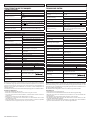
BOTTICELLI BT AV 650 - 19
D814253 0AN00_01

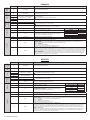
Codice
diagnostica
Descrizione Note
STRE Attivazione ingresso start esterno START E
OPEN Attivazione ingresso OPEN
CLS Attivazione ingresso CLOSE
PED Attivazione ingresso pedonale PED
STOP Attivazione ingresso STOP
PHOT Attivazione ingresso fotocellula PHOT
BAR Attivazione ingresso costa BAR
SWC Attivazione ingresso necorsa chiusura del motore SWC
SWO Attivazione ingresso necorsa apertura del motore SWO
SET
La scheda stà attendendo di eseguire una manovra completa apertura-
chiusura non interrotta da stop intermedi per acquisire la coppia necessaria
al movimento.
ATTENZIONE! Non è attivo il rilevamento dell’ostacolo
ER01 Test fotocellule fallito Vericare collegamento fotocellule e/o impostazioni logiche
ER02 Test costa fallito Vericare collegamento coste e/o impostazioni logiche
ER06 Test costa 8k2 fallito Vericare collegamento coste e/o impostazioni parametri/logiche
ER1x*Errore test hardware scheda -Vericare collegamenti al motore
- Problemi hardware alla scheda (contattare l’assistenza tecnica)
ER3x*Inversione per ostacolo - Amperostop Vericare eventuali ostacoli lungo il percorso
ER4x*Termica Attendere il rareddamento dell’automazione
ER70, ER71
ER74, ER75 Errore interno di controllo supervisione sistema. Provare a spegnere e riaccendere la scheda. Se il problema persiste contattare
l’assistenza tecnica.
ER72 Errore di consistenza dei parametri di centrale (Logiche e Parametri) Premendo Ok vengono confermate le impostazioni rilevate. La scheda
continuerà a funzionare con le impostazioni rilevate.
E’ necessario vericare le impostazioni della scheda (Parametri e Logiche).
ER73 Errore nei parametri di D-track Premendo Ok la scheda riprenderà a funzionare con D-track di default.
E’ necessario eettuare un autoset
ERf4 Protezione per cortocircuito o sovraccarico uscita accessori Vericare l’assorbimento o la presenza di cortocircuiti sull’uscita accessori,
VSafe, lampeggiante.
01 Autoset non eseguito correttamente per intervento di comandi esterni.
Ripetere la procedura
02 Corsa inferiore alla corsa minima richiesta , circa 50 cm.
03
L’installazione risulta troppo “elastica/dinamica”. Provvedere a irrigidirla
aggiungendo un fermo meccanico sul necorsa di chiusura (kit cod. I100025
10005) prima di eseguire un ulteriore autoset.
* X = 0,1,…,9,A,B,C,D,E,F
Diagnostics
code DESCRIPTION NOTES
STRE START E external start input activated
OPEN OPEN input activated
CLS CLOSE input activated
PED PED pedestrian input activated
STOP STOP input activated
PHOT PHOT photocell input activated
BAR BAR safety edge input activated
SWC SWC motor closing limit switch input activated
SWO SWO motor opening limit switch input activated
SET
The board is standing by to perform a complete opening-closing cycle uninter-
rupted by intermediate stops in order to acquire the torque required for movement.
WARNING! Obstacle detection not active
ER01 Photocell test failed Check photocell connection and/or logic settings
ER02 Safety edge test failed Check safety edge connection and/or logic settings
er06 8k2 safety edge test failed Check safety edge connection and/or parameter/logic settings
ER1x*Board hardware test error - Check connections to motor
- Hardware problems with board (contact technical assistance)
ER3x*Reverse due to obstacle - Amperostop Check for obstacles in path
ER4x*Thermal cutout Allow automated device to cool
ER70, ER71
ER74, ER75 Internal system supervision control error. Try switching the board o and back on again. If the problem persists,
contact the technical assistance department.
ER72 Consistency error of the control unit’s parameters (Logics and Parameters) Pressing OK the detected settings are conrmed. The board will keep
on working with the detected settings.
The board settings must be checked (Parameters and Logics)
ER73 D-track parameter error Pressing OK, the board will keep on working with D-track as a default.
An autoset is required
ERf4 Short circuit or overload protection for accessory output Check the absorption or the presence of short circuits on the accessory
output, VSafe, ashing.
01 Autoset not correctly performed due to intervention of external commands. Repeat
the procedure
02 Travel less than the minimum required travel, about 50 cm.
03 The installation is too "resilient/oscillating". Tighten it by adding a mechanical stop to
the closure limit-switch (kit code I100025 10005) before performing a further autoset.
* X = 0,1,…,9,A,B,C,D,E,F
ITALIANO
ENGLISH
20 - BOTTICELLI BT AV 650
D814253 0AN00_01
La page est en cours de chargement...
La page est en cours de chargement...
La page est en cours de chargement...
La page est en cours de chargement...
La page est en cours de chargement...
La page est en cours de chargement...
La page est en cours de chargement...
La page est en cours de chargement...
-
 1
1
-
 2
2
-
 3
3
-
 4
4
-
 5
5
-
 6
6
-
 7
7
-
 8
8
-
 9
9
-
 10
10
-
 11
11
-
 12
12
-
 13
13
-
 14
14
-
 15
15
-
 16
16
-
 17
17
-
 18
18
-
 19
19
-
 20
20
-
 21
21
-
 22
22
-
 23
23
-
 24
24
-
 25
25
-
 26
26
-
 27
27
-
 28
28


BFT BOTTICELLI BT AV 650 Manuel utilisateur
- Taper
- Manuel utilisateur
dans d''autres langues
- italiano: BFT BOTTICELLI BT AV 650 Manuale utente
- español: BFT BOTTICELLI BT AV 650 Manual de usuario
- Deutsch: BFT BOTTICELLI BT AV 650 Benutzerhandbuch
- Nederlands: BFT BOTTICELLI BT AV 650 Handleiding

