Support Honeywell ADT 2X16AIO Home Security Panel Guide d'installation
- Taper
- Guide d'installation

ADT ADT2X16AIO Installation and Setup Guide
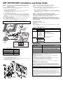
STEP 1 - Installing the Rechargeable Backup Battery and
Power Connector
The ADT ADT2X16AIO is designed to be placed on a desk/table top with the stand
attached or mounted to a wall using the back plate/cover.
1. Remove the ADT2X16AIO Case Back.
2. Install the applicable Communications module(s) (ADTLTE, POTSMODULE, or
ADTZWM -Wi-Fi® and Z-Wave®).
2. Connect the battery connector to the receptacle on the PC board.
3. Insert the Battery Pack into the case.
4. Secure the Battery Pack with the Battery Retainer using the Retaining Screw.
5a. Connect the power cable to the GND and +9V terminals on the ADT2X16AIO
and to the + and – terminals on the Power Supply. Do not apply power at this
time. OR
5b Connect the power supply connector to the receptacle on the ADT2X16AIO. Do
not apply power at this time.
NOTE: If using the optional wall mount configuration, skip to the wall mounting
procedure. If not, complete step 7.
6. Install the Case Back onto the ADT2X16AIO and secure with the screw.
Optional ADTLTE, ADTZWM and POTSMODULE Communications Module Note: Refer
to the Specific Module Installation section in the online Installation & Reference Guide for
instructions on mounting this module.
BATTERY
ADTZWM
MODULE
ADTLTE
MODULE
COVER
SCREW SCREW
grip-034-V0
SCREW
TERMINAL BLOCK
POWER
SUPPLY
RECEPTACLE
DETAIL A
BATTERY
CONNECTOR
EXT INT
MACHINE
SCREW
GND
9V
Table 1 – Wiring Guide
Maximum distance between
power supply and control
Wire Gauge
(AWG)
Note:
Use UL-listed limited energy
cable
Up to 25 feet (7.62m) # 22
Up to 45 feet (13.72m) # 20
Up to 70 feet (21.34m) # 18
Up to 110 feet (33.53m) # 16
Mounting the Base to a Wall (Optional)
For wall mounting, perform to the following:
1. Secure the Mounting Plate to the wall with 4 screws.
2. Install the Tamper Screw as shown.
3. Secure the ADT2X16AIO to the Mounting Plate by aligning the slots on the Base
and sliding the unit down until locked in position.
4. Secure the control with the screw.
BATTERY
grip-035-V0
STEP 2 - Setting up the Communication Links
Note: Do not connect to a receptacle controlled by a switch.
1. Plug the power supply into a 24-hour, 110VAC unswitched outlet. Upon power-
up, the “Please Standby!” will be displayed on the home screen.
2. Connect the Control to the local router.
Tools → Master User Code → Wi-Fi Settings → Scan for Network OR
Manually Connect to Network OR WPS → Enter required information OR
follow prompts → OK
STEP 3 - Registration Programming and Testing
Registration, Programming and Testing is conducted through ADT 3rd Party Services
and the Alarm.com MobileTech tool. On a laptop, PC or Smart Device, go to:
https://3ps.adt.com and https://alarmadmin.alarm.com/mobile.
IMPORTANT: Once the programming procedure has started and the unit is
powered up, do not remove power or disconnect the battery, nor open the case.
Disconnecting power or activating the tamper switch can cause unpredictable
programming results.
Testing the System
The following test modes are available:
Walk Test:
Communication Test
Refer to the Quick Guide to User Functions (P/N 800-24344 or higher) for information
on these test modes.
System LED Functions
LED Status Meaning
POWER Green – Steady AC Connected/Battery Charged
Red – Blinking Low Battery
Off No AC Power
STATUS Green – Steady System is Ready to Arm
Red – Steady System Armed
Red – Flashing Alarm or Alarm Memory
Red – Flashing
Alternately with
TROUBLE LED
(Flashing Amber)
System is in Programming Mode
Off System is Not Ready to Am
TROUBLE Amber – Steady System Trouble
Amber Flashing Device Trouble
Amber – Flashing
Alternately with
STATUS LED
(Flashing Red)
System is in Programming Mode
Off Normal System Status (No Troubles Present)
Specifications
Dimensions: 7.93” W x 5.76” H x 1.10” D
Voltage Input: P/N 300-10260: White – 9VDC, 2.5A
P/N 300-10260-BK (Black) – 9VDC, 2.5A
4-Hour Backup Battery: P/N 300-10342: Rechargeable Backup Battery:
Lithium-ion battery pack rated at 3.6V, 2480AH
Optional 24-Hour Backup
Battery:
P/N 300-10186PK: Rechargeable Backup Battery Kit:
Lithium-ion battery pack rated at 3.6/4.2V, 7500 mAH
Communication Formats: 4-Digit Contact ID
Contacting Technical Support
PLEASE, before you call Technical Support, be sure you:
READ THE INSTRUCTIONS!
• Determine that the power supply and/or backup battery are supplying proper
voltages.
• Verify your programming information where applicable.
• Note the proper model number of this product, and the version level (if known)
along with any documentation that came with the product.
• Note your ADT customer number and/or company name.
Having this information handy will make it easier for us to serve you quickly and
effectively.
For Documentation and Online Support
See Installation and Setup Guide P/N 800-24341 or higher, which can be
ordered by contacting Customer Service at 1-800-238-2727 (1-800-ADT-
ASAP). For technical support please call the ADT Product Support Group at
1-877-748-7628, option 3.
Warning: this unit includes an alarm verification feature that will result in a delay of
the system alarm signal from the indicated circuits. The total delay (control unit plus
smoke detectors) shall not exceed 60 seconds. No other smoke detector shall be
connected to these circuits unless approved by the local authority having jurisdiction.
Avertissement: Cette unité peut être programmée pour utiliser une fonction de
vérification d’alarme d’incendie qui entraîne un délai dans la signalisation des
alarmes provenant des circuits dédiés à l’incendie. Le délai total (unité de commande
et détecteurs de fumée) ne doit pas dépasser 60 secondes. Aucun autre détecteur de
fumée ne doit être raccordé à ces circuits sans l’approbation des autorités
compétentes locales.
Note Each protected circuit within this control is supervised.

The Limitations
o
f
t
his Alarm System
While this system is an advanced design security system, it does not offer guaranteed protection
against burglary or fire or other emergency. Any alarm system, whether commercial or
residential, is subject to compromise or failure to warn for a variety of reasons. For example:
• Intruders may gain access through unprotected openings or have the technical sophistication
to bypass an alarm sensor or disconnect an alarm warning device.
• Intrusion detectors (e.g., passive infrared detectors), smoke detectors, and many other
sensing devices will not work without power. Battery-operated devices will not work without
batteries, with dead batteries, or if the batteries are not put in properly. Devices powered
solely by AC will not work if their AC power supply is cut off for any reason, however briefly.
• Signals sent by wireless transmitters may be blocked or reflected by metal before they reach
the alarm receiver. Even if the signal path has been recently checked during a weekly test,
blockage can occur if a metal object is moved into the path.
• A user may not be able to reach a panic or emergency button quickly enough.
• While smoke detectors have played a key role in reducing residential fire deaths in the United
States, they may not activate or provide early warning for a variety of reasons in as many as
35% of all fires, according to data published by the Federal Emergency Management Agency.
Some of the reasons smoke detectors used in conjunction with this System may not work are
as follows. Smoke detectors may have been improperly installed and positioned. Smoke
detectors may not sense fires that start where smoke cannot reach the detectors, such as in
chimneys, in walls, or roofs, or on the other side of closed doors. Smoke detectors also may
not sense a fire on another level of a residence or building. A second-floor detector, for
example, may not sense a first-floor or basement fire. Moreover, smoke detectors have
sensing limitations. No smoke detector can sense every kind of fire every time. In general,
detectors may not always warn about fires caused by carelessness and safety hazards like
smoking in bed, violent explosions, escaping gas, improper storage of flammable materials,
overloaded electrical circuits, children playing with matches, or arson. Depending upon the
nature of the fire and/or the locations of the smoke detectors, the detector, even if it operates
as anticipated, may not provide sufficient warning to allow all occupants to escape in time to
prevent injury or death
• Passive Infrared Motion Detectors can only detect intrusion within the designed ranges as
diagrammed in their installation manual. Passive Infrared Detectors do not provide volumetric
area protection. They do create multiple beams of protection, and intrusion can only be
detected in unobstructed areas covered by those beams. They cannot detect motion or
intrusion that takes place behind walls, ceilings, floors, closed doors, glass partitions, glass
doors, or windows. Mechanical tampering, masking, painting or spraying of any material on
the mirrors, windows or any part of the optical system can reduce their detection ability.
Passive Infrared Detectors sense changes in temperature; however, as the ambient
temperature of protected area approaches the temperature range of 90° to 105°F, the
detection performance can decrease.
• Alarm warning devices such as sirens, bells, or horns may not alert people or wake up
sleepers if they are located on the other side of closed or partly open doors. If warning
devices sound on a different level of the residence from the bedrooms, then they are less
likely to waken or alert people inside the bedrooms. Even persons who are awake may not
hear the warning if the alarm is muffled from a stereo, radio, air conditioner or other appliance,
or by passing traffic. Finally, alarm warning devices, however loud, may not warn hearing-
impaired people or waken deep sleepers.
• Telephone lines needed to transmit alarm signals from a premises to a central monitoring
station may be out of service or temporarily out of service. Telephone lines are also subject to
compromise by sophisticated intruders.
• Even if the system responds to the emergency as intended, however, occupants may have
insufficient time to protect themselves from the emergency situation. In the case of a
monitored alarm system, authorities may not respond appropriately.
• This equipment, like other electrical devices, is subject to component failure. Even though this
equipment is designed to last as long as 10 years, the electronic components could fail at any
time.
The most common cause of an alarm system not functioning when an intrusion or fire occurs is
inadequate maintenance. This alarm system should be tested weekly to make sure all sensors
and transmitters are working properly.
Installing an alarm system may make one eligible for lower insurance rates, but an alarm system
is not a substitute for insurance. Homeowners, property owners, and renters should continue to
act prudently in protecting themselves and continue to insure their lives and property.
We continue to develop new and improved protection devices. Users of alarm systems owe it to
themselves and their loved ones to learn about these developments.
RF Exposure
Warning –
The antenna(s) used for this device must be installed to provide a separation
distance of at least 7.8 inches (20 cm) from all persons and must not be co-located or operating
in conjunction with any other antenna or transmitter except in accordance with FCC and ISED
multi-transmitter product procedures.
Mise en Garde
Exposition aux Frequences Radio:
La/les antenne(s) utilisée(s) pour cet émetteur
doit/doivent être installée(s) à une distance de séparation d'au moins 20 cm (7,8 pouces) de
toute personne et ne pas être située(s) ni fonctionner parallèlement à tout autre transmetteur ou
antenne, excepté en conformité avec les procédures de produit multi transmetteur FCC et
ISEDs.
This equipment should be installed in accordance with National Electrical Code,
NFPA 70, Standard for the Installation of Residential Fire Warning Systems,
CAN/ULC-S540 and Chapter 2 of the National Fire Alarm Code, ANSI/NFPA 72
(National Fire Protection Association, Batterymarch Park, Quincy, MA 02269). Printed
information describing proper installation, operation, testing, maintenance, evacuation
planning, and repair service is to be provided with this equipment.
Warning: Owner’s instruction notice: ’Not to be removed by anyone except occupant
Avertissement : Avis du propriétaire : « Ne doit être retiré par personne, saut
l’occupant. »
This system must be checked by a qualified technician at least once
every three (3) years
WARRANTY INFORMATION
For the latest warranty information, please go to:
www.honeywell.com/security/hsc/resources/wa.
For patent information, see www.honeywell.com/patents
Warranty
Patents
Recommenda
tions
f
or Proper Protection
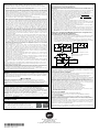
The Following Recommendations for the Location of Fire and Burglary Detection Devices Help
Provide Proper Coverage for the Protected Premises.
Recommendations for Smoke and Heat Detectors
With regard to the number and placement of smoke/heat detectors, we subscribe to the
recommendations contained in the National Fire Protection Association's (NFPA) Standard #72
noted below.
Early warning fire detection is best achieved by the installation of fire detection equipment in all
rooms and areas of the household as follows: For minimum protection a smoke detector
should be installed outside of each separate sleeping area, and on each additional floor of a
multi-floor family living unit, including basements. The installation of smoke detectors in
kitchens, attics (finished or unfinished), or in garages is not normally recommended.
For additional protection the NFPA recommends that you install heat or smoke detectors in the
living room, dining room, bedroom(s), kitchen, hallway(s), attic, furnace room, utility and
storage rooms, basements and attached garages.
In addition, we recommend the following:
• Install a smoke detector inside every bedroom where a smoker sleeps.
• Install a smoke detector inside every bedroom where someone sleeps with the door partly
or completely closed. Smoke could be blocked by the closed door. Also, an alarm in the
hallway outside may not wake up the sleeper if the door is closed.
• Install a smoke detector inside bedrooms where electrical appliances (such as portable
heaters, air conditioners or humidifiers) are used.
• Install smoke detectors at both ends if the hallway is more than 40 feet (12 meters) long.
• Install smoke detectors in any room where an alarm control is located, or in any room
where alarm control connections to an AC source or phone lines are made. If detectors
are not so located, a fire within the room could prevent the control from reporting a fire or
an intrusion.
This Control Complies with NFPA Requirements for Temporal Pulse
Sounding of Fire Notification Appliances
Recommendations for Proper Intrusion Protection
• For proper intrusion coverage, sensors should be located at every possible point of entry
to a home or premises. This would include any skylights that may be present, and the
upper windows in a multi-level building.
• In addition, we recommend that radio backup be used in a security system. This will
ensure that alarm signals can be sent to the alarm monitoring station in the event that the
communications are out of order (if connected to an alarm monitoring station).
DINING
KITCHEN BEDROOM
BEDROOM
BEDROOM
BEDROOM
LIVING ROOM BEDROOM
BDRM
DINING
LIVING ROOM
TV ROOM KITCHEN
BEDROOM BEDROOM
TO
BR
LVNG RM
BASEMENT
KTCHN
.
CLOSED
DOOR
GARAGE
Smoke Detectors for Minimum Protection
Smoke Detectors for Additional Protection
Heat-Activated Detectors
BDRM
floor_plan-001-V1
.
Federal Communications Commission & ISED Statements
The user shall not make any changes or modifications to the equipment unless authorized by
the Installation Instructions or User's Manual. Unauthorized changes or modifications could
void the user's authority to operate the equipment.
CLASS B DIGITAL DEVICE STATEMENT
This equipment has been tested to FCC requirements and has been found acceptable for use.
The FCC requires the following statement for your information:
This equipment generates and uses radio frequency energy and if not installed and used
properly, that is, in strict accordance with the manufacturer's instructions, may cause
interference to radio and television reception. It has been type tested and found to comply with
the limits for a Class B computing device in accordance with the specifications in Part 15 of
FCC Rules, which are designed to provide reasonable protection against such interference in a
residential installation. However, there is no guarantee that interference will not occur in a
particular installation. If this equipment does cause interference to radio or television reception,
which can be determined by turning the equipment off and on, the user is encouraged to try to
correct the interference by one or more of the following measures:
• If using an indoor antenna, have a quality outdoor antenna installed.
• Reorient the receiving antenna until interference is reduced or eliminated.
• Move the radio or television receiver away from the receiver/control.
• Move the antenna leads away from any wire runs to the receiver/control.
• Plug the receiver/control into a different outlet so that it and the radio or television receiver
are on different branch circuits.
• Consult the dealer or an experienced radio/TV technician for help.
ISED CLASS B STATEMENT
This Class B digital apparatus complies with Canadian ICES-003.
Cet appareil numérique de la classe B est conforme à la norme NMB-003 du Canada.
FCC / ISED STATEMENT
This device complies with Part 15 of the FCC Rules, and ISED’s license-exempt RSSs.
Operation is subject to the following two conditions: (1) This device may not cause harmful
interference, and (2) This device must accept any interference received, including interference
that may cause undesired operation.
Cet appareil est conforme à la partie 15 des règles de la FCC et exempt de licence RSS ISED.
Son fonctionnement est soumis aux conditions suivantes: (1) Cet appareil ne doit pas causer
d’interférences nuisibles. (2) Cet appareil doit accepter toute interférence reçue y compris les
interférences causant une réception indésirable.
Responsible Party / Issuer of Supplier’s Declaration of Conformity: Honeywell International, 2
Corporate Center Drive., Melville, NY 11747, Ph: 516-577-2000
.
ADT Security Services, Inc.
1501 Yamato Road
Boca Raton, FL 33431
Copyright © 2018 ADT Security Services
Ê800-24343ÁŠ
800-24343 5/18 Rev. A
-
 1
1
-
 2
2


Support Honeywell ADT 2X16AIO Home Security Panel Guide d'installation
- Taper
- Guide d'installation
dans d''autres langues
Autres documents
-
Honeywell 408EU Manuel utilisateur
-
System Sensor Limitations of Fire Alarm Systems Manuel utilisateur
-
Apollo 51000-355 Guide d'installation
-
SCS DAAF-1Y-CE Installation and Use Manual
-
QOLSYS QS5110-840 IQSmoke Wireless Smoke Heat Alarm Le manuel du propriétaire
-
-
Risco RWX34S Installation Instructions Manual
-
Chacon 34953 Manuel utilisateur
-
DSC HS2TCHP Manuel utilisateur