Horizon Fitness EX-58 Le manuel du propriétaire
- Catégorie
- Tapis de course
- Taper
- Le manuel du propriétaire
Ce manuel convient également à

ELLIPTICAL OWNER’S MANUAL
MANUEL DU PROPRIÉTAIRE DE L’EXERCISEUR ELLIPTIQUE
MANUAL DEL PROPIETARIO DE LA MÁQUINA ELÍPTICA
Read the ELLIPTICAL GUIDE before using this OWNER’S MANUAL.
Lire le GUIDE D’UTILISATION DE L’EXERCISEUR ELLIPTIQUE avant de se servir du présent MANUEL DU PROPRIÉTAIRE.
Lea la GUÍA DEL USUARIO DE LA MÁQUINA ELÍPTICA antes de usar este MANUAL DEL PROPIETARIO.
EX-78EX-68
GS1050E
EX-58
CE5.1


3
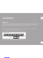
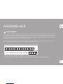
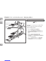
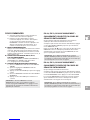
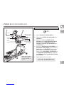
ASSEMBLY
There are several areas during the assembly process that special attention must be paid. It is very important to follow the assembly
instructions correctly and to make sure all parts are firmly tightened. If the assembly instructions are not followed correctly, the
elliptical could have frame parts that are not tightened and will seem loose and may cause irritating noises. To prevent damage to
the elliptical, the assembly instructions must be reviewed and corrective actions should be taken.
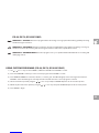
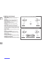
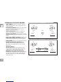
Before proceeding, find your elliptical’s serial number located on the front stabilizer tube and enter it in the space provided
below. Also locate the model name which is next to the serial number.
ENTER YOUR SERIAL NUMBER AND MODEL NAME IN THE BOXES BELOW:
» Refer to the SERIAL NUMBER and MODEL NAME when calling for service.
» Be sure to enter both the SERIAL NUMBER and MODEL NAME on your warranty card.
SERIAL NUMBER:
MODEL NAME: HORIZON ELLIPTICAL
WARNING


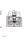
6
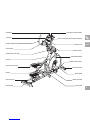
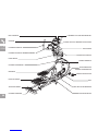
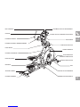
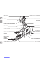
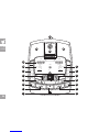
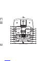
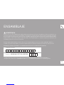
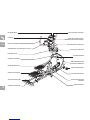
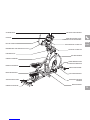
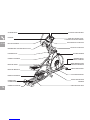
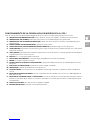
PIVOTING FOOT PADS
CRANK
TOP CAP
PEDAL ARM
SPEAKERS
WATER BOTTLE HOLDER
UPPER HANDLEBAR
PULSE GRIPS
CONSOLE
ON/OFF SWITCH
STABILIZER TUBE
POWER CORD SOCKET
MAIN FRAME
GUIDE RAIL SET
REAR COVER
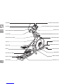
IPOD/MP3 PLAYER POCKET
CONSOLE FAN
CONSOLE MAST
TOUCH PAD PANEL AND DISPLAY WINDOWS
LOWER HANDLEBAR
LOWER LINK ARM
INCLINE COVER
EX-78

7
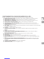
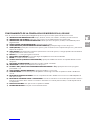
TOOLS INCLUDED:
FScrewdriver
F8 mm L-Wrench
F6 mm L-Wrench
F5 mm L-Wrench
F13/15 mm Flat Wrench
PARTS INCLUDED:
F1 Main Frame
F1 Stabilizer Tube
F1 Guide Rail Set
F2 Pedal Arms
F2 Lower Handlebars
F2 Upper Handlebars
F2 Lower Link Arms With Footpads
F1 Top Cap
F1 Top Cap Rear Cover
(EX-68, EX-78 and GS1040E only)
F1 Console Mast
F1 Console Mast Boot
F1 Console
F2 Handlebar Caps
F1 Water Bottle Holder
F1 Rear Cover (EX-78 only)
F1 Audio Adapter Cable
F1 Power Cord
F7 Hardware Bags
UNPACKING
Unpack the product where you will be using it. Place the elliptical carton on a level flat
surface. It is recommended that you place a protective covering on your floor. Never
open box when it is on its side.
NOTE: During each assembly step, ensure that ALL nuts and bolts are in place and
partially threaded in before completely tightening any ONE bolt.
NOTE: A light application of grease may aid in the installation of hardware. Any grease,
such as lithium bike grease is recommended.
If you have questions or if
there are any missing parts,
contact Customer Tech
Support. Contact information
is located on the back panel
of this manual.
NEED HELP?
PRE ASSEMBLY
ALL
MODELS

8
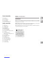
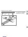
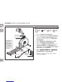
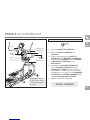
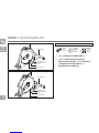
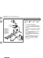
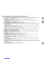
ASSEMBLY STEP 1
A Open hardware bag 1.
B Attach the stabilizer tube to the main
frame using 4 bolts (a), 4 spring
washers (b) and 4 arc washers (c).
BOLT (A)
30 mm
Qty: 4
SPRING WASHER (B)
15 mm
Qty: 4
ARC WASHER (C)
17 mm
Qty: 4
HARDWARE BAG 1 CONTENTS :
BOLTS (A)
SPRING WASHERS (B)
ARC WASHERS (C)
STABILIZER TUBE
MAIN FRAME
BOLTS (A)
SPRING WASHERS (B)
ARC WASHERS (C)
STABILIZER TUBE
MAIN FRAME
ALL
MODELS
EX-58 SHOWN
EX-78 SHOWN

9
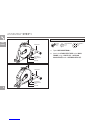
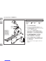
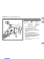
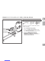
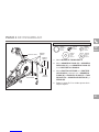
CE5.1, EX-58, EX-68, GS1050E ASSEMBLY STEP 2
* This step is for CE5.1, EX-58, EX-68, GS1050E
models only.
A Open hardware bag 2.
B Align guide rail set with main frame as
shown.
C Attach the guide rail set to the main frame
using 4 bolts (d), 4 flat washers (e) and 4
tooth washers (g).
HARDWARE BAG 2 CONTENTS :
TOOTH WASHERS (G)
FLAT WASHERS (E)
GUIDE RAIL SET
BOLTS (D)
MAIN FRAME
CE5.1, EX-58 SHOWN
CE5.1
EX-58
EX-68
GS1050E
TOOTH WASHER (G)
15 mm
Qty: 4
FLAT WASHER (E)
17 mm
Qty: 4
BOLT (D)
55 mm
Qty: 4

10
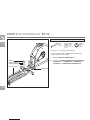
EX-78 ASSEMBLY STEP 2
TOOTH WASHERS (G)
FLAT WASHERS (E)
GUIDE RAIL SET
BOLTS (D)
MAIN FRAME
EX-78 ONLY
EX-78
* This step is for EX-78 models only.
* CE5.1, EX-58, EX-68, GS1050E models skip to STEP 3.
A Open hardware bag 2.
B Attach the guide rail set to the main frame
using 4 bolts (d), 4 flat washers (e) and 4
tooth washers (g).
TOOTH WASHER (G)
15 mm
Qty: 4
FLAT WASHER (E)
17 mm
Qty: 4
BOLT (D)
55 mm
Qty: 4
HARDWARE BAG 2 CONTENTS (For Steps A–B):

11
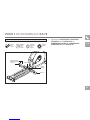
EX-78 ASSEMBLY STEP 2
EX-78
SPRING WASHER (B)
15 mm
Qty: 4
FLAT WASHER (I)
16 mm
Qty: 4
BOLT (H)
35 mm
Qty: 4
NUT (J)
Qty: 4
GUIDE RAILS
MAIN FRAME
BOLTS (H)
SPRING WASHERS (B)
FLAT WASHERS (I)
NUTS (J)
C Attach the guide rails to the main frame
using 4 bolts (h), 4 flat washers (i), 4
spring washers (b) and 4 nuts (j).
HARDWARE BAG 2 CONTENTS (For Step C) :

12
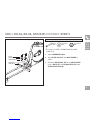
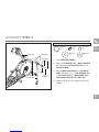
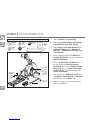
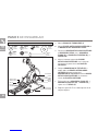
ASSEMBLY STEP 3
ALL
MODELS
EX-78 SHOWN
BOLT (M)
SPRING WASHER (B)
FLAT WASHER (K)
WAVY WASHER (L)
PEDAL ARM
CRANK
PEDAL ARM WHEEL
GUIDE RAIL
CONSOLE MAST
PRE-INSTALLED BOLTS
CONSOLE CABLE
MAIN FRAME
NOTE: Be
careful not
to pinch any
wires while
attaching the
console mast.
A Open hardware bag 3.
B Carefully pull the console cable through
the console mast using the twist tie located
inside the console mast.
C Gently slide the console mast onto the
main frame and attach console mast to
main frame using pre-installed bolts.
D Slide wavy washer (l) over crank
followed by pedal arm as shown. Rest
pedal arm wheel on guide rail.
E Attach the pedal arm to the crank using 1
flat washer (k), 1 spring washer (b)
and 1 bolt (m).
F Repeat steps E–F on the opposite side of the
elliptical.
BOLT (M)
20 mm
Qty: 2
SPRING WASHER (B)
15 mm
Qty: 2
FLAT WASHER (K)
20 mm
Qty: 2
WAVY WASHER (L)
22.5 mm
Qty: 2
HARDWARE BAG 3 CONTENTS :

13
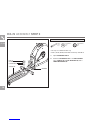
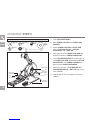
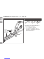
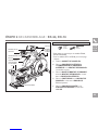
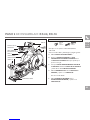
ASSEMBLY STEP 4
A Open hardware bag 4.
B Silde 1 flat washer (n), 1 wavy washer
(l) and another flat washer (n) onto the
console mast.
C Slide lower handlebar onto console
mast and attach using 1 flat washer (n),
1 flat washer (k), 1 handlebar cap, 1
spring washer (b) and 1 bolt (m).
D Repeat steps B–C on the opposite side of the
elliptical.
BOLT (M)
20 mm
Qty: 2
SPRING WASHER (B)
15 mm
Qty: 2
FLAT WASHER (K)
20 mm
Qty: 4
WAVY WASHER (L)
22.5 mm
Qty: 2
FLAT WASHER (N)
25 mm
Qty: 6
HARDWARE BAG 4 CONTENTS :EX-78 SHOWN
BOLT (M)
SPRING
WASHER (B)
FLAT WASHERS (K)
FLAT WASHERS (N)CONSOLE MAST
HANDLEBAR
CAP
LOWER HANDLEBAR
WAVY WASHER (L)
ALL
MODELS

14
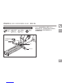
BOLT (O)
SPRING WASHER (B)
FLAT WASHER (E)
FLAT WASHER (K)
BOLT (M)
NUT (J)
LOWER HANDLEBAR
SPRING WASHER (B)
TEFLON WASHERS (P)
LOWER LINK ARM
PEDAL ARM BRACKET
ASSEMBLY STEP 5
ALL
MODELS
A Open hardware bag 5.
B Slide lower link arm onto pedal arm
bracket.
C Attach lower link arm to pedal arm
using 1 flat washer (k), 1 spring
washer (b) and 1 bolt (m).
D Align opposite end of lower link arm with
bracket on bottom of lower handlebar.
E Place teflon washers (p) on both sides of
the lower link arm. While holding teflon
washers (p) slide lower link arm into
bottom end of lower handlebar.
F Secure the joint with 1 flat washer (e), 1
spring washer (b),1 bolt (o) and secure
with 1 nut (j).
G Repeat steps B–F on the opposite side of the
elliptical.
BOLT (M)
20 mm
Qty: 2
SPRING WASHER (B)
15 mm
Qty: 4
FLAT WASHER (K)
20 mm
Qty: 2 TEFLON
WASHER (P)
28.4 mm
Qty: 4
FLAT WASHER (E)
17 mm
Qty: 2
NUT (J)
Qty: 2 BOLT (O)
70 mm
Qty: 2
HARDWARE BAG 5 CONTENTS :
EX-78 SHOWN

15
EX-68
EX-78
GS1050E
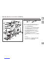
EX-68, EX-78 ASSEMBLY STEP 6
* This step is for EX-68, EX-78, GS1050E models only.
* CE5.1 and EX-58 models skip to next page.
A Open hardware bag 6.
B Silde top cap and top cap rear cover
over console mast and snap into place.
C Slide console mast boot around
console mast and insert into top cap.
D Slide water bottle holder over
console mast and attach using 3 bolts
(r).
EX-78 only:
E Slide rear cap over rear stabilizer
and attach using 2 screws (q).
BOLT (R)
12 mm
Qty: 3
EX-78 only:
SCREW (Q)
15 mm
Qty: 2
HARDWARE BAG 6 CONTENTS :EX-78 SHOWN
WATER
BOTTLE
HOLDER
CONSOLE MAST
CONSOLE MAST BOOT
TOP CAP
BOLT (R)
SCREWS (Q)
REAR CAP (EX-78 ONLY)
BOLTS (R)
TOP CAP
REAR
COVER
REAR STABILIZER

16
WATER
BOTTLE
HOLDER
CONSOLE MAST
CONSOLE MAST BOOT
SCREW (S)
SCREWS (S)
TOP CAP
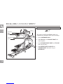
CE5.1
EX-58
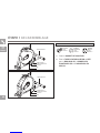
EX-58, CE5.1 ASSEMBLY STEP 7
* This step is for CE5.1 and EX-58 models only.
* EX-68, EX-78, GS1050E models skip to next page.
A Open hardware bag 7.
B Silde top cap over console mast and
snap into place.
C Insert console mast boot over top cap
and snap into place.
D Slide water bottle holder over
console mast and attach using 3
screws (s).
HARDWARE BAG 7 CONTENTS :
SCREW (S)
12 mm
Qty: 3

17
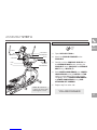
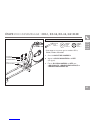
ALL
MODELS
A Open hardware bag 8.
B Attach the CONSOLE CABLES to the
CONSOLE.
C Carefully tuck the CONSOLE CABLES into
the CONSOLE MAST before attaching the
CONSOLE. Attach CONSOLE to CONSOLE
MAST using 4 BOLTS (T).
D Slide UPPER HANDLEBARS onto LOWER
HANDLEBARS and align NOTCH with TAB
making sure handlebars are joined together
completely. Secure UPPER HANDLEBARS
to LOWER HANDLEBARS using PRE-
ATTACHED SET SCREWS.
E Repeat step D on other side.
YOU ARE FINISHED!
ASSEMBLY STEP 8
BOLT (T)
10 mm
Qty: 4
HARDWARE BAG 8 CONTENTS :CE5.1, EX-58 SHOWN
CONSOLE
CONSOLE MAST
BOLTS (T)
UPPER HANDLEBAR
CONSOLE CABLES
LOWER HANDLEBAR
PRE-INSTALLED
SET SCREWS
NOTCH
TAB
NOTE: Be careful not
to pinch any wires while
attaching the console.


19
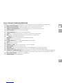
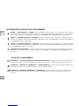
ELLIPTICAL OPERATION
This section explains how to use your elliptical’s console and programming.
The BASIC OPERATION section in the ELLIPTICAL GUIDE has instructions for the following:
• LOCATION OF THE ELLIPTICAL
• POWER/GROUNDING INSRUCTIONS
• FOOT POSITIONING
• MOVING THE ELLIPTICAL
• LEVELING THE ELLIPTICAL
• POWER/MANUAL INCLINE OPERATION
• USING THE HEART RATE FUNCTION

La page est en cours de chargement...
La page est en cours de chargement...
La page est en cours de chargement...
La page est en cours de chargement...
La page est en cours de chargement...
La page est en cours de chargement...
La page est en cours de chargement...
La page est en cours de chargement...
La page est en cours de chargement...
La page est en cours de chargement...
La page est en cours de chargement...
La page est en cours de chargement...
La page est en cours de chargement...
La page est en cours de chargement...
La page est en cours de chargement...
La page est en cours de chargement...
La page est en cours de chargement...
La page est en cours de chargement...
La page est en cours de chargement...
La page est en cours de chargement...
La page est en cours de chargement...
La page est en cours de chargement...
La page est en cours de chargement...
La page est en cours de chargement...
La page est en cours de chargement...
La page est en cours de chargement...
La page est en cours de chargement...
La page est en cours de chargement...
La page est en cours de chargement...
La page est en cours de chargement...
La page est en cours de chargement...
La page est en cours de chargement...
La page est en cours de chargement...
La page est en cours de chargement...
La page est en cours de chargement...
La page est en cours de chargement...
La page est en cours de chargement...
La page est en cours de chargement...
La page est en cours de chargement...
La page est en cours de chargement...
La page est en cours de chargement...
La page est en cours de chargement...
La page est en cours de chargement...
La page est en cours de chargement...
La page est en cours de chargement...
La page est en cours de chargement...
La page est en cours de chargement...
La page est en cours de chargement...
La page est en cours de chargement...
La page est en cours de chargement...
La page est en cours de chargement...
La page est en cours de chargement...
La page est en cours de chargement...
La page est en cours de chargement...
La page est en cours de chargement...
La page est en cours de chargement...
La page est en cours de chargement...
La page est en cours de chargement...
La page est en cours de chargement...
La page est en cours de chargement...
La page est en cours de chargement...
La page est en cours de chargement...
La page est en cours de chargement...
La page est en cours de chargement...
La page est en cours de chargement...
La page est en cours de chargement...
La page est en cours de chargement...
La page est en cours de chargement...
La page est en cours de chargement...
La page est en cours de chargement...
La page est en cours de chargement...
La page est en cours de chargement...
La page est en cours de chargement...
La page est en cours de chargement...
La page est en cours de chargement...
La page est en cours de chargement...
La page est en cours de chargement...
La page est en cours de chargement...
La page est en cours de chargement...
La page est en cours de chargement...
La page est en cours de chargement...
La page est en cours de chargement...
La page est en cours de chargement...
La page est en cours de chargement...
-
 1
1
-
 2
2
-
 3
3
-
 4
4
-
 5
5
-
 6
6
-
 7
7
-
 8
8
-
 9
9
-
 10
10
-
 11
11
-
 12
12
-
 13
13
-
 14
14
-
 15
15
-
 16
16
-
 17
17
-
 18
18
-
 19
19
-
 20
20
-
 21
21
-
 22
22
-
 23
23
-
 24
24
-
 25
25
-
 26
26
-
 27
27
-
 28
28
-
 29
29
-
 30
30
-
 31
31
-
 32
32
-
 33
33
-
 34
34
-
 35
35
-
 36
36
-
 37
37
-
 38
38
-
 39
39
-
 40
40
-
 41
41
-
 42
42
-
 43
43
-
 44
44
-
 45
45
-
 46
46
-
 47
47
-
 48
48
-
 49
49
-
 50
50
-
 51
51
-
 52
52
-
 53
53
-
 54
54
-
 55
55
-
 56
56
-
 57
57
-
 58
58
-
 59
59
-
 60
60
-
 61
61
-
 62
62
-
 63
63
-
 64
64
-
 65
65
-
 66
66
-
 67
67
-
 68
68
-
 69
69
-
 70
70
-
 71
71
-
 72
72
-
 73
73
-
 74
74
-
 75
75
-
 76
76
-
 77
77
-
 78
78
-
 79
79
-
 80
80
-
 81
81
-
 82
82
-
 83
83
-
 84
84
-
 85
85
-
 86
86
-
 87
87
-
 88
88
-
 89
89
-
 90
90
-
 91
91
-
 92
92
-
 93
93
-
 94
94
-
 95
95
-
 96
96
-
 97
97
-
 98
98
-
 99
99
-
 100
100
-
 101
101
-
 102
102
-
 103
103
-
 104
104


Horizon Fitness EX-58 Le manuel du propriétaire
- Catégorie
- Tapis de course
- Taper
- Le manuel du propriétaire
- Ce manuel convient également à