
2019 Cervis, Inc.
U120.0.1
Split Receiver System Manual
™

This document is the property of Cervis, Inc. and cannot be copied, modified, e-mailed, or reproduced without the express
prior written consent of Cervis, Inc.
Cervis, Inc. reserves the right to change this manual or edit, delete, or modify any information without prior notification.
FCC Statements
15.19 – Two Part Warning
This device complies with Part 15 of the FCC rules. Operation is subject to the following two conditions:
(1) This device may not cause harmful interference and
(2) This device must accept any interference received, including interference that may cause undesired operation.
15.21 – Unauthorized Modification
NOTICE: The manufacturer is not responsible for any unauthorized modifications to this equipment made by the user. Such modifications could
void the user’s authority to operate the equipment.
15.105(b) – Note:
This equipment has been tested and found to comply with the limits for a Class B digital device, pursuant to Part 15 of the FCC Rules. These
limits are designed to provide reasonable protection against harmful interference in a residential installation. This equipment generates, uses and
can radiate radio frequency energy and, if not installed and used in accordance with the instructions, may cause harmful interference to radio
communications. However, there is no guarantee that interference will not occur in a particular installation. If this equipment does cause harmful
interference to radio or television reception, which can be determined by turning the equipment off and on, the user is encouraged to try to
correct the interference by one or more of the following measures:
Reorient or relocate the receiving antenna.
Increase the separation between the equipment and receiver.
Connect the equipment into an outlet on a circuit different from that to which the receiver is connected.
Industry Canada Statement
This device complies with Canadian RSS-210.
The installer of this radio equipment must ensure that the antenna is located or pointed such that it does not emit RF field in excess of Health Canada limits
for the general population; consult Safety Code 6, obtainable from Health Canada’s website https://www.canada.ca/en/health-
canada/services/environmental-workplace-health/reports-publications/radiation/safety-code-6-health-canada-radiofrequency-exposure-guidelines-
environmental-workplace-health-health-canada.html.
Le présent appareil est conforme à la norme CNR-210 d'Industrie Canada.
L'installateur de cet équipement radio doit s'assurer que l'antenne est située ou orientée de façon à ne pas émettre un champ RF dépassant les limites de
Santé Canada pour la population générale; consulter le Code de sécurité 6, disponible sur le site Web de Santé Canada https://www.canada.ca/en/health-
canada/services/environmental-workplace-health/reports-publications/radiation/safety-code-6-health-canada-radiofrequency-exposure-guidelines-
environmental-workplace-health-health-canada.html.
Industry Canada Statement
This device complies with Industry Canada licence-exempt RSS standard(s). Operation is subject to the following two conditions: (1) this device may not
cause interference, and (2) this device must accept any interference, including interference that may cause undesired operation of the device.
Le présent appareil est conforme aux CNR d'Industrie Canada applicables aux appareils radio exempts de licence. Le fonctionnement est soumis aux deux
conditions suivantes : (1) cet appareil ne doit pas causer d'interférences, et (2) cet appareil doit accepter toute interférence, y compris les interférences
susceptibles de causer un fonctionnement non désiré de l'appareil.
IC Unlicensed Devices EIRP Statements for Removable Antennas
Part 1: Under Industry Canada regulations, this radio transmitter may only operate using an antenna of a type and maximum (or lesser) gain
approved for the transmitter by Industry Canada. To reduce potential radio interference to other users, the antenna type and its gain should be so
chosen that the equivalent isotropically radiated power (e.i.r.p.) is not more than that necessary for successful communication.
Partie 1 : Conformément à la réglementation d'Industrie Canada, le présent émetteur radio peut fonctionner avec une antenne d'un type et d'un gain maximal
(ou inférieur) approuvé pour l'émetteur par Industrie Canada. Dans le but de réduire les risques de brouillage radioélectrique à l'intention des autres
utilisateurs, il faut choisir le type d'antenne et son gain de sorte que la puissance isotrope rayonnée équivalente (p.i.r.e.) ne dépasse pas l'intensité
nécessaire à l'établissement d'une communication satisfaisante.
Part 2: This radio transmitter (LOBSRF-305) has been approved by Industry Canada to operate with the antenna type listed below with the
maximum permissible gain and required antenna impedance for each antenna type indicated. Antenna types not included in this list, having a
gain greater than the maximum gain indicated for that type, are strictly prohibited for use with this device.
Partie 2 : Cet émetteur radio (LOBSRF-305) a été approuvé par Industrie Canada pour fonctionner avec le type d'antenne indiqué ci-dessous avec le gain
maximal admissible et l'impédance d'antenne requise pour chaque type d'antenne indiqué. Il est strictement interdit d'utiliser avec cet appareil un type
d'antenne ne figurant pas dans cette liste ou ayant un gain supérieur au gain maximum indiqué pour ce type.

Split Receiver System Manual
2019 Cervis, Inc.
i
Table of Contents
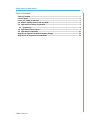
Table of Contents .......................................................................................................................... i
List of Figures .............................................................................................................................. ii
Cervis, Inc. Safety Precautions .................................................................................................. 1
1.0 Warrior Split Receivers RX#1 and RX#2 ............................................................................ 2
2.0 Split Receiver Theory of Operation .................................................................................... 3
2.1 Terminology ...................................................................................................................... 6
3.0 Split Receiver Association .................................................................................................. 7
4.0 Split Receiver Operation ................................................................................................... 11
Appendix A: Exposure to Radio Frequency Energy .............................................................. 13
Appendix B: RF Exposure Considerations ............................................................................. 13

U120.0.1
ii
List of Figures
Figure 1. Warrior MU-X9 Receivers and 900MHz External Antennas ........................................2
Figure 2. HH2S Transmitter Button Control/LED Function ........................................................3
Figure 3. Receiver 1 Wiring Diagram ............................................................................................4
Figure 4. Receiver 2 Wiring Diagram ............................................................................................5
Figure 5. Split Receiver System Configuration ...........................................................................7
Figure 6. Split Receiver System Wiring Diagram ..................................................................... 12

Split Receiver System Manual
Cervis, Inc. Safety Precautions
Read and follow all instructions.
Failure to abide by Safety Precautions may cause equipment failure, loss of authority
to operate the equipment, and personal injury.
Use and maintain proper wiring. Follow equipment manufacturer instructions.
Improper, loose, and frayed wiring can cause system failure, equipment damage, and
intermittent operation.
Changes or modifications made to equipment not expressly approved by the
manufacturer will void the warranty.
Owner/operators of the equipment must abide by all applicable Federal, State, and
Local laws concerning installation and operation of the equipment. Failure to comply
could result in penalties and could void user authority to operate the equipment.
Make sure that the machinery and surrounding area is clear before operating. Do not
activate the remote control system until certain that it is safe to do so.
Turn off the handheld remote and remove power from the receiver before attempting
any maintenance. This will prevent accidental operation of the controlled machinery.
Use a damp cloth to keep units clean. Remove mud, concrete, dirt, etc. after use to
prevent obstructing or clogging the buttons, levers, wiring, and switches.
Do not allow liquid to enter the handheld or receiver enclosures. Do not use high
pressure equipment to clean the handheld remote or receiver.
Disconnect the radio receiver before welding on the machine. Failure to disconnect
the base unit may result in destruction of or damage to the receiver.
Operate and store units only within the specified operation and storage temperatures
defined in the specifications of this document.
Keep high-energy RF devices away from handheld remotes. Activation of high-power
communication radios, for instance, in close proximity to handheld remotes can
result in interference and “false” circuit activation.
Do not key 2-way radios while using the handheld remote.

U120.0.1
2
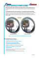
1.0 Warrior Split Receivers RX#1 and RX#2
Warrior split receivers RX#1 and RX#2 are machine-mounted receivers intended for use on
industrial cranes and hoists. Seen below in the 900MHz FCC Part 15 license-free radio band,
the standard MU-X9 receiver is self-contained and preconfigured for bridge and trolley/hoist
control.
This split bridge trolley/hoist system is designed in such a way that the designated bridge
receiver (RX#1) provide main line contactor (MLC), warning/start, and three-contact bridge
motion control. The second receiver (RX#2) provides three-contact trolley and hoist commands
as well as its own mainline and warning start relay outputs that can be utilized, if desired.
Factory mounted 90dB warning buzzers (see Figure 1) may be included if purchased with the
primary system.
Figure 1. Warrior MU-X9 Receivers and 900MHz External Antennas
Warrior MU-X9 Receiver Features
Two Motion, Two Speed Control
Two Series MLC (Main Line Contactor) Relays
Dedicated Horn/Light and Start Relays
Compact Designed to IP65/IP67 Standards
900MHz @ 100mW No License Required Operation
Designed to ICS 8 NEMA Crane Specification
External Antenna
Self-Contained, Factory Pre-Configured Terminal Wiring
with Single Pigtail Harness
14 Screw Terminals for Optional Custom User Wiring
RX#1 Bridge/Mainline
RX#2 Trolley/Hoist
Optional 90dB
Warning Buzzer

Split Receiver System Manual
2019 Cervis, Inc.
3
2.0 Split Receiver Theory of Operation
The split receiver setup uses two receivers:
1. One wired to the bridge/mainline contactor (MLC) control.
2. One wired to control the trolley/hoist control panel.
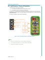
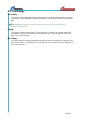
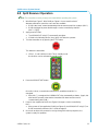
A Warrior HH2S handheld remote transmitter simultaneously controls both receivers after they
are properly associated. LEDs on the transmitter are used for diagnostics, including indication of
dual receiver mode.
See Figure 2 for button controls and LED indications.
Figure 2. HH2S Transmitter Button Control/LED Function
Notes:
1. Receiver 1 (RX#1) will have a custom software configuration.
2. The handheld remote will have a custom software configuration.
3. A green boot identifies the transmitter.
Control
RX#2
Outputs
Control
RX#1
Outputs
Used for
Association
Dual RX
Mode
Radio Transmit/ Receive
Battery Life
1
3
5
7
9
2
4
6
8
10
1
3
2
4

U120.0.1
4
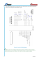
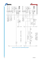
Receiver 1 (RX#1)
This receiver is designated for the bridge/main line contactor (MLC) and must be mounted and
wired to that control panel as illustrated in Figure 3.
Figure 3. Receiver 1 Wiring Diagram
Note: At various times throughout system startup, relay K7 energizes to alert the operator
that the receiver is on and “linked” with the transmitter. Relay K7 should be wired to a horn or
light to take advantage of this feature. See Figure 6 for master installation drawing.

Split Receiver System Manual
2019 Cervis, Inc.
5
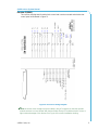
Receiver 2 (RX#2)
This receiver is designated for trolley/hoist control and must be mounted and wired to that
control panel as illustrated in Figure 4.
Figure 4. Receiver 2 Wiring Diagram
Note: At various times throughout system startup, relay K7 energizes to alert the operator
that the receiver is on and “linked” with the transmitter. Relay K7 should be wired to a horn or
light to take advantage of this feature. See Figure 6 for master installation drawing.

U120.0.1
6
2.1 Terminology
Association
The process of exchanging and storing serial numbers. This allows the transmitter and receiver
to work as a system. Association is done at the factory, but may have to be done in the field as
well.
Note: Multiple transmitters can be associated to the receivers. First-come/first-serve
operation is always active.
Pairing
The process of linking a transmitter (TX) to a receiver (RX). Pairing can only take place if the
transmitter(s) and receivers have been associated. Only one TX can be paired to an RX at a
time (First come/First Serve).
MLC Relays
Two safety relays in the radio package that are wired in series and energize the customer main
line contactor (MLC). The radio MLC is shut off with any communication fault, thus killing power
to the crane controls.

Split Receiver System Manual
2019 Cervis, Inc.
7
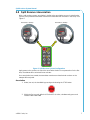
3.0 Split Receiver Association
With a split receiver system, association is similar to the association process in other Warrior
systems, except that the transmitter must be associated with both receivers in the set up. See
Figure 5.
Figure 5. Split Receiver System Configuration
Apply power to the receivers to unlock the association window. Once powered on for the first
time, the window will be unlocked for two minutes.
Once association has started, the transmitter must be associated to both receivers or the
attempt will be rejected.
Association
1. Wake (turn on) the handheld by pressing and releasing the STOP button.
2. Within the first second, while the B Select LED is active, simultaneously press and
release buttons 9 and 10.
Receiver 1 (RX#1)
Receiver 2 (RX#2)

U120.0.1
8
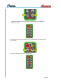
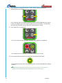
Handheld LEDs begin cycling (see below), indicating that the handheld is in
maintenance mode.
3. Simultaneously press and hold buttons 3 (UP) and 4 (DOWN) for approximately
five seconds.
4. Release the buttons when LED A starts to blink.
9
10
3
4

Split Receiver System Manual
2019 Cervis, Inc.
9
5. The TX/RX LED and B Selection LEDs light steady, indicating that the handheld
is attempting to locate all available Warrior receivers within their two-minute
unlocked association window.
6. Once the handheld has completed its search—and one or more receivers have
been logged in the handheld’s memory—the TX/RX LED and A Selection LEDs
light steady.
Note: If no receivers are available, the handheld will stay in scan mode until the
handheld times out or is turned off.
7. Next, a detected receiver will start blinking its strobe LED indicator and/or
sounding its audible alarm. The operator may confirm or deny that selection.

U120.0.1
10
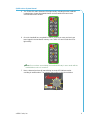
8. Press button 10 to confirm that receiver, or press button 9 to deny that receiver
and move to the next receiver.
Once confirmed, the first receiver is stored in memory as RX#1 (bridge/main line control).
It closes its mainline relay, which supplies power to the second receiver. The transmitter
then starts the nomination process again for RX#2 (trolley/hoist control).
9. Press button 10 to confirm RX#2.
The TX/RX LED starts blinking rapidly, indicating communication is established.
The selected receiver is stored in the transmitter memory slot as RX#2.
10. Once the two desired receivers are stored, press the HORN/START button.
The transmitter launches into normal operating mode, communicating with both selected
receivers.
Note: With this split bridge, trolley/hoist receiver setup; after the first receiver is
selected, the transmitter will automatically detect the second receiver.
9
10
10

Split Receiver System Manual
2019 Cervis, Inc.
11
4.0 Split Receiver Operation
Note: The transmitter must be properly associated before operating the system.
1. Wire RX#1 per Figure 3. Wire RX#2 per Figure 4. Use a transfer switch if
alternate methods to control the crane are also available.
RX#1 is the “main” control and should pull in the crane’s main line contactor (MLC
1
).
RX#2 should get its power feed through a contact controlled by that MLC
(MLC
1
: [1]/[2]).
2. Apply power to RX#1.
The HORN/LIGHT relay (K7) momentarily energizes.
If wired to an indicating device (horn, light), this alerts the operator.
3. Turn the transmitter on by pressing the STOP button.
This wakes the transmitter.
LEDs 1, 3, and 4 will be on solid. This is standby mode.
No functions can be activated in standby mode
4. Press the HORN/START button.
Once this is done, communication with RX#1 is established and MLC
1
is
energized.
When MLC
1
is energized, the HORN/LIGHT relay momentarily activates. (Again, this
alert lets the operator know that the transmitter has been turned on and is
communicating with RX#1.)
5. Power is then supplied to RX#2 (see Figure 6) through a contact controlled by
MLC
1
.
When power is first supplied to RX#2 (see Figure 6), the HORN/LIGHT relay (K7) on
RX#2 momentarily activates. MLC
2
will be energized.
6. Once both receivers are powered on and go through this start-up sequence, the
system is ready for operation.

U120.0.1
12
Figure 6. Split Receiver System Wiring Diagram

Split Receiver System Manual
2019 Cervis, Inc.
13
Appendix A: Exposure to Radio Frequency Energy
Warrior handheld remote units and receivers contain radio transceivers. When active, a
handheld remote sends out radio frequency (RF) energy through its internal antenna. The
Warrior handheld remote complies with limits set by the United States Federal Communication
Commission (FCC) for operating distance from human tissue.
Appendix B: RF Exposure Considerations
The radio module may be used in a variety of host applications that fall into two general
categories:
1. Mobile applications: Those where any operating locations are not on a human
body. In mobile applications, the host application is typically fixed to mobile
equipment, with either an internal or external antenna.
2. Portable applications: Those where the transmitting equipment is located on the
hand, arm, or other part of the human body. In portable applications, the
equipment is typically held in the hand of an operator or affixed to the torso on
either a belt or harness.
Equipment containing the radio module has been evaluated for RF exposure hazards by two
approaches:
1. Maximum Permissible Exposure (MPE) for mobile applications.
2. Specific Absorption Rate (SAR) for portable applications.
The required separation distances are measured from the actual location of the radiated part of
the antenna. An antenna may be inside the host application, affixed to the enclosure of the host
application, or at the end of an optional extension coaxial cable.
Mobile Applications
Equipment must be located at least 20cm away from areas likely to be occupied by an unaware
person.
Handheld Applications
All operators of handheld equipment with any type of antenna require proper equipment
operation training, and such training must include RF exposure safety instructions. Once training
is completed, they are considered “aware persons.”
If the portable operating pose is on the hand or arm, a 5mm separation is required between the
radiating part of the antenna and nearby human tissue.
Required Training
All installers and operators of host applications that include an SRF310 radio transceiver module
must be trained to use proper RF safety precautions.

-
 1
1
-
 2
2
-
 3
3
-
 4
4
-
 5
5
-
 6
6
-
 7
7
-
 8
8
-
 9
9
-
 10
10
-
 11
11
-
 12
12
-
 13
13
-
 14
14
-
 15
15
-
 16
16
-
 17
17
-
 18
18


dans d''autres langues
- English: Cervis Warrior MU-X9
Documents connexes
Autres documents
-
ADEMCO 2C2BHTRAN Remote Control Manuel utilisateur
-
LUNASEA LL64 Le manuel du propriétaire
-
 Remtron Command Pro 21R10 Manuel utilisateur
-
 deako DS2005 Manuel utilisateur
-
Vuzix 492 Manuel utilisateur
-
EnOcean PTM 535U Manuel utilisateur
-
Yamaha V1 Mode d'emploi
-
Samson Concert 288 Manuel utilisateur
-
-
Tele Radio AB ONFC1414A Manuel utilisateur

