
2018 Cervis, Inc.
EBU-xH24XF Base Unit
User Manual
U109.0.0
™

SmaRT EBU-xH24XF Base Unit
This document is the property of Cervis, Inc. and cannot be copied, modified, e-mailed, or reproduced without the express
prior written consent of Cervis, Inc.
Cervis, Inc. reserves the right to change this manual or edit, delete, or modify any information without prior notification.
FCC Statements
15.19 – Two Part Warning
This device complies with Part 15 of the FCC rules. Operation is subject to the following two conditions:
(1) This device may not cause harmful interference and
(2) This device must accept any interference received, including interference that may cause undesired operation.
15.21 – Unauthorized Modification
NOTICE: The manufacturer is not responsible for any unauthorized modifications to this equipment made by the user. Such modifications could
void the user’s authority to operate the equipment.
15.105(b) – Note:
This equipment has been tested and found to comply with the limits for a Class B digital device, pursuant to Part 15 of the FCC Rules. These
limits are designed to provide reasonable protection against harmful interference in a residential installation. This equipment generates, uses and
can radiate radio frequency energy and, if not installed and used in accordance with the instructions, may cause harmful interference to radio
communications. However, there is no guarantee that interference will not occur in a particular installation. If this equipment does cause harmful
interference to radio or television reception, which can be determined by turning the equipment off and on, the user is encouraged to try to
correct the interference by one or more of the following measures:
Reorient or relocate the receiving antenna.
Increase the separation between the equipment and receiver.
Connect the equipment into an outlet on a circuit different from that to which the receiver is connected.
Industry Canada Statement
This device complies with Canadian RSS-210.
The installer of this radio equipment must ensure that the antenna is located or pointed such that it does not emit RF field in excess of Health Canada limits for
the general population; consult Safety Code 6, obtainable from Health Canada’s website www.hc-sc.gc-ca/rpb.
Le présent appareil est conforme aux CNR d'Industrie Canada applicables aux appareils radio
exempts de licence. L'exploitation est autorisée aux deux conditions suivantes : (1) l'appareil ne doit pas produire de brouillage, et (2) l'utilisateur de l'appareil
doit accepter tout brouillage
radioélectrique subi, même si le brouillage est susceptible d'en compromettre le fonctionnement.
Industry Canada Statement
This device complies with Industry Canada licence-exempt RSS standard(s). Operation is subject to the following two conditions: (1) this device may not cause
interference, and (2) this device must accept any interference, including interference that may cause undesired operation of the device.
Le présent appareil est conforme aux CNR d'Industrie Canada applicables aux appareils radio exempts de licence. L'exploitation est autorisée aux deux
conditions suivantes : (1) l'appareil ne doit pas produire de brouillage, et (2) l'utilisateur de l'appareil doit accepter tout brouillage radioélectrique subi, même si
le brouillage est susceptible d'en compromettre le fonctionnement.
IC Unlicensed Devices EIRP Statements for Removable Antennas
Part 1: Under Industry Canada regulations, this radio transmitter may only operate using an antenna of a type and maximum (or lesser) gain
approved for the transmitter by Industry Canada. To reduce potential radio interference to other users, the antenna type and its gain should be so
chosen that the equivalent isotropically radiated power (e.i.r.p.) is not more than that necessary for successful communication.
Conformément à la réglementation d'Industrie Canada, le présent émetteur radio peut fonctionner avec une antenne d'un type et d'un gain maximal (ou
inférieur) approuvé pour l'émetteur par Industrie Canada. Dans le but de réduire les risques de brouillage radioélectrique à l'intention des autres utilisateurs,
il faut choisir le type d'antenne et son gain de sorte que la puissance isotrope rayonnée équivalente (p.i.r.e.) ne dépasse pas l'intensité nécessaire à
l'établissement d'une communication satisfaisante.
Part 2: This radio transmitter (LOBSRF-305) has been approved by Industry Canada to operate with the antenna type listed below with the
maximum permissible gain and required antenna impedance for each antenna type indicated. Antenna types not included in this list, having a
gain greater than the maximum gain indicated for that type, are strictly prohibited for use with this device.
Le présent émetteur radio (LOBSRF-305) a été approuvé par Industrie Canada pour fonctionner avec les types d'antenne énumérés ci-dessous et ayant un
gain admissible maximal et l'impédance requise pour chaque type d'antenne. Les types d'antenne non inclus dans cette liste, ou dont le gain est supérieur
au gain maximal indiqué, sont strictement interdits pour l'exploitation de l'émetteur.
RoHS Compliance Statement
Cervis, Inc. complies with the requirements of Restriction of Hazardous Substances (RoHS/WEEE) Specification based on in-house practice and
declaration of compliance from our vendors. For additional information concerning RoHS compliance, please contact Cervis, Inc. at:
CERVIS, Inc.
170 Thorn Hill Road Warrendale, PA 15086
Phone: 724.741.9000 Fax: 724.741.9001
This product may contain material that may be hazardous to human health and the environment. In
compliance with EU Directive 2002/96/EC on Waste Electrical and Electronic Equipment (WEEE):
Do not dispose of the product as unsorted municipal waste.
This product should be recycled in accordance with local regulations. Contact local
authorities for detailed information.
This product may be returnable to the distributor for recycling. Contact your distributor
for details.

User Manual
2018 Cervis, Inc.
i
Table of Contents
List of Figures ............................................................................................................................... i
List of Tables ................................................................................................................................. i
Cervis Inc. Safety Precautions ................................................................................................... ii
1.0 SmaRT EBU-xH24XF Base Unit Introduction .................................................................... 1
2.0 Features ................................................................................................................................ 1
3.0 EBU-xH24XF LEDs ............................................................................................................... 2
4.0 EBU-xH24XF Mounting ........................................................................................................ 3
5.0 EBU-xH24XF Wiring ............................................................................................................. 3
5.1 Harnesses HN-1026 and HN-1027 ................................................................................... 3
5.2 Individual Wiring Harness Models HN-1016 to HN-1019 ............................................... 6
6.0 SmaRT Handheld & Base Unit Remote Association ........................................................ 8
7.0 SmaRT EBU-xH24XF Specifications .................................................................................. 9
Appendix A: Exposure to Radio Frequency Energy .............................................................. 10
Appendix B: Agency Identification Label Locations .............................................................. 10
Appendix C: Antennas, Extensions, and Kits ......................................................................... 10
Appendix D: EBU-xH24XF Model Specifications .................................................................... 11
Appendix E: EBU-xH24XF Cable Harness Options ................................................................ 11
List of Figures
Figure 1. SmaRT EBU-xH24XF Base Unit .................................................................................... 1
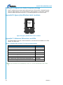
Figure 2. EBU-xH24XF Mounting Dimensions ............................................................................ 3
Figure 3. EBU-xH24XF Base Unit and Harness HN-1026 Pinouts ............................................. 4
Figure 4. EBU-xH24XF Base Unit and Harness HN-1027 Pinouts ............................................. 5
Figure 5. EBU-xH24XF Base Unit Harness HN-1016 (Socket A) ................................................ 6
Figure 6. EBU-xH24XF Base Unit Harness HN-1017 (Socket C) ................................................ 6
Figure 7. EBU-xH24XF Base Unit Harness HN-1018 (Socket B) ................................................ 7
Figure 8. EBU-xH24XF Base Unit Harness HN-1019 (Socket D) ................................................ 7
Figure 9. SmaRT EBU-xH24XF Associate Illustration with Various SmaRT Handhelds......... 8
Figure 10. Agency Identification Label Locations .................................................................... 10
List of Tables
Table 1. EBU-xH24XF LEDs........................................................................................................... 2
Table 2. EBU-xH24XF LEDs........................................................................................................... 2
Table 3. HN-1026 and HN-1027 Cable Harnesses Pins to Flying Leads Assignments ........... 4
Table 4. EBU-xH24XF Base Unit Harness HN-1016 (Socket A) ................................................. 6
Table 5. EBU-xH24XF Base Unit Harness HN-1017 (Socket C) ................................................. 6
Table 6. EBU-xH24XF Base Unit Harness HN-1018 (Socket B) ................................................. 7
Table 7. EBU-xH24XF Base Unit Harness HN-1019 (Socket D) ................................................. 7
Table 8. EBU-xH24XF Base Unit Specifications.......................................................................... 9
Table 9. Compatible EBU-xH-24XF-7773 External Antenna Details ........................................ 10
Table 10. EBU-xH24XF Cable Harnesses .................................................................................. 11

SmaRT EBU-xH24XF Base Unit
U109.0.0
ii
Cervis Inc. Safety Precautions
Read and follow all instructions.
Failure to abide by Safety Precautions may result in equipment failure, loss of
authority to operate the equipment, and personal injury.
Use and maintain proper wiring. Follow equipment manufacturer instructions.
Improper, loose, and frayed wiring can cause system failure, equipment damage, and
intermittent operation.
Changes or modifications made to equipment not expressly approved by the
manufacturer will void the warranty.
Owner/operators of the equipment must abide by all applicable Federal, State, and
Local laws concerning installation and operation of the equipment. Failure to comply
could result in penalties and could void user authority to operate the equipment.
Make sure that the machinery and surrounding area is clear before operating. Do not
activate the remote control system until certain that it is safe to do so.
Turn off the handheld remote and remove power from the base unit before attempting
any maintenance. This will prevent accidental operation of the controlled machinery.
Power can be removed from the Base Unit by detaching the 12-pin cables from the
base unit connectors A, B, C and D, or by removing the source power from the circuit.
Use a damp cloth to keep units clean. Remove mud, concrete, dirt, etc. after use to
prevent obstructing or clogging the buttons, levers, wiring, and switches.
Do not allow liquid to enter the handheld or base unit enclosures. Do not use high
pressure equipment to clean the handheld remote or base unit.
Disconnect the radio base unit before welding on the machine. Failure to disconnect
the base unit may result in destruction of or damage to the base unit.
Operate and store units only within the specified operation and storage temperatures
defined in the specifications of this document.
Keep high-energy RF devices away from handheld remotes. Activation of high-power
communication radios, for instance, in close proximity to handheld remotes can
result in interference and “false” circuit activation.
Do not key 2-way radios while using the handheld remote.

User Manual
1.0 SmaRT EBU-xH24XF Base Unit Introduction
The versatile EBU-xH24XF base units feature an H-Bridge, sixteen FET (field effect transistor)
high-side switching outputs or switch-to-ground digital inputs, two Form C relays, and CAN Bus
control capability. Using Direct Sequence Spread Spectrum (DSSS) wireless technology at
900MHz or 2.4GHz, the base unit provides a robust link with a SmaRT handheld remote in
congested radio environments. It accepts a broad range of input power with operating voltages
ranging from 7VDC to 28VDC. The rugged weatherproof enclosure allows these units to operate
worry free in harsh weather conditions. Four 12-wire color-keyed weatherproof connecting
cables connect the controlled devices.
SmaRT base units feature seamless communications association to SmaRT handheld remotes
without the need to open either the handheld remote or base unit
2.0 Features
DSSS Technology (900MHz @ 10mW or 2.4GHz @ 100mW)
Quad Connectors for Ease of Wiring with Power on Each Connector
Sixteen FET Outputs/Inputs
Weatherproof
Eight Current Sense Channels
CAN Bus Capable
H-Bridge
Five Diagnostic LEDs
Power Cutoff FET
Two Analog Outputs
Two Form C Relays
Four Analog Inputs
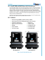
Figure 1. SmaRT EBU-xH24XF Base Unit
EBU-xH24XF-INT
EBU-xH24XF-EXT

SmaRT EBU-xH24XF Base Unit
U109.0.0
2
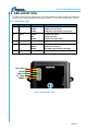
3.0 EBU-xH24XF LEDs
The EBU-xH24XF has five status/system LEDs that indicate the current state of the active base
unit and can be used for troubleshooting when necessary. These LEDs are defined in Table 1.
Table 1. EBU-xH24XF LEDs
LED
Name
Color
Indication
1
CAN TX/RX
RED
GREEN
AMBER
CAN Transmit only active
CAN Receive only active
CAN TX/RX active flashes per message
2
Out/In
GREEN
RED
AMBER
Outputs only active
Inputs only active
Outputs and inputs active
3
Health
GREEN
Flash 1/s when health OK
4
RF TX/RX
RED
GREEN
AMBER
RF Transmit only active
RF Receive only active
RF TX/RX active flashes per message
5
Power
AMBER
OK when amber
Table 2. EBU-xH24XF LEDs
CAN TX/RX
OUT/IN
HEALTH
RF TX/RX
POWER

User Manual
2018 Cervis, Inc.
3
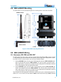
4.0 EBU-xH24XF Mounting
The EBU-xH24XF can be mounted using the four mounting holes on the sides of the EBU.
Figure 2. EBU-xH24XF Mounting Dimensions
5.0 EBU-xH24XF Wiring
5.1 Harnesses HN-1026 and HN-1027
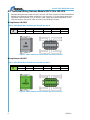
The EBU-xH24XF has four 12-pin connector sockets listed as A, C, D, and B as shown in Figure
2. Cable harness HN-1026 and HN-1027 are typically used to plug into the appropriate sockets
of the EBU-xH24XF and then wired to the necessary individual outputs.
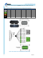
Harness HN-1026 (Figure 3) has a gray 12-pin plug that connects to EBU socket A and a
green 12-pin plug that connects to EBU socket C. The 90 inch (total, connector to lead
ends) cable harness contains the combined 24-wires ending with 24 individually numbered
6 inch flying leads for wiring to appropriate outputs.
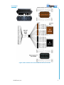
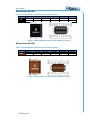
Harness HN-1027 (Figure 4) has a brown 12-pin plug that connects to EBU socket D and
a black 12-pin plug that connects to EBU socket B. The 90 inch (total, connector to lead
ends) cable harness contains the combined 24-wires ending with 24 individually numbered
6 inch flying leads for wiring to appropriate outputs.
Table 3 defines the cable plug pins, the pin type, and the match to the numbered flying lead. For
instance: Pin 1 of Connector A is described as 1:M1: 1, where 1(connector pin): M1 (the defined
163.200
143.00
221.554
204.713
71.400
71.400
143.00
53.30
211.178
183.00
Socket A C D B
115mm
2.4GHz Antenna
900MHz Antenna
42.69mm

SmaRT EBU-xH24XF Base Unit
U109.0.0
4
output):, and 1 (numbered flying lead). Appendix E Table 10 lists available cable harness
options.
Table 3. HN-1026 and HN-1027 Cable Harnesses Pins to Flying Leads Assignments
Conn.
Pins to Leads Assignments (Pin: Type: Lead)
A
1: M1: 1
2: M2: 2
3: M3: 3
4: M4: 4
5: M5: 5
6: M6: 6
7: M7: 7
8: M8: 8
9: +VIN: 9
10: +VIN: 10
11: GND: 11
12: GND: 12
C
1: M9: 13
2: M10: 14
3: M11: 15
4: M12: 16
5: M13: 17
6: M14: 18
7: M15: 19
8: M16: 20
9: +VIN: 21
10: +VIN: 22
11: GND: 23
12: GND: 24
D
1: M17 NC: 1
2: M17 COM: 2
3: M17 NO: 3
4: M18 NC: 4
5: M18 COM: 5
6: M18 NO: 6
7: M19: 7
8: M20: 8
9: +VIN: 9
10: +VIN: 10
11: GND: 11
12: GND: 12
B
1: CANH: 13
2: CANL: 14
3: CANTERM: 15
4: RS232TX: 16
5: RS232RX: 17
6: M21: 18
7: M22: 19
8: M23: 20
9: M24: 21
10: +VIN: 22
11: GND: 23
12: GND: 24
Figure 3. EBU-xH24XF Base Unit and Harness HN-1026 Pinouts

User Manual
2018 Cervis, Inc.
5
Figure 4. EBU-xH24XF Base Unit and Harness HN-1027 Pinouts

SmaRT EBU-xH24XF Base Unit
U109.0.0
6
5.2 Individual Wiring Harness Models HN-1016 to HN-1019
Individual wiring harness models HN-1016, HN-1017, HN-1018, and HN-1019 are illustrated and
defined in the following four tables and figures. Each have pins (1-12) that directly relate to the
individually numbered leads (1-12) of the each cable, though the output assignments of each
cable are unique to the specific cable as shown in the following four tables.
Wiring Harness HN-1016
Table 4. EBU-xH24XF Base Unit Harness HN-1016 (Socket A)
Socket
Pins 1 through 12 Assignments
A
1: M1
2: M2
3: M3
4: M4
5: M5
6: M6
7: M7
8: M8
9: +VIN
10: +VIN
11: GND
12: GND
Figure 5. EBU-xH24XF Base Unit Harness HN-1016 (Socket A)
Wiring Harness HN-1017
Table 5. EBU-xH24XF Base Unit Harness HN-1017 (Socket C)
Socket
Pins 1 through 12 Assignments
C
1: M9
2: M10
3: M11
4: M12
5: M13
6: M14
7: M15
8: M16
9: +VIN
10: +VIN
11: GND
12: GND
Figure 6. EBU-xH24XF Base Unit Harness HN-1017 (Socket C)

User Manual
2018 Cervis, Inc.
7
Wiring Harness HN-1018
Table 6. EBU-xH24XF Base Unit Harness HN-1018 (Socket B)
Socket
Pins 1 through 12 Assignments
B
1: CANH
2: CANL
3: CANTERM
4: RS232TX
5: RS232RX
6: M21
7: M22
8: M23
9: M24
10: +VIN
11: GND
12: GND
Figure 7. EBU-xH24XF Base Unit Harness HN-1018 (Socket B)
Wiring Harness HN-1019
Table 7. EBU-xH24XF Base Unit Harness HN-1019 (Socket D)
Socket
Pins 1 through 12 Assignments
D
1: M17 NC
2: M17 COM
3: M17 NO
4: M18 NC
5: M18 COM
6: M18 NO
7: M19
8: M20
9: +VIN
10: +VIN
11: GND
12: GND
Figure 8. EBU-xH24XF Base Unit Harness HN-1019 (Socket D)

SmaRT EBU-xH24XF Base Unit
U109.0.0
8
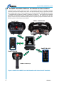
6.0 SmaRT Handheld & Base Unit Remote Association
A SmaRT remote control system must have communications between the SmaRT handheld
control unit and the EBU-xH24XF base unit is set up at the factory using an Associate process
prior to shipping the system. The Associate process can be performed in the field when necessary
— troubleshooting or replacing a SmaRT component for instance — using the Associate method
prescribed in the particular SmaRT handheld remote manual that was originally sent with the
system. Please refer to the handheld remote manual or Engineering System manual that was sent
with the system for Associate process details.
Figure 9. SmaRT EBU-xH24XF Associate Illustration with Various SmaRT Handhelds
SmaRT MCB
SmaRT Console Box
SmaRT Pistol Grip
SmaRT HH-xH06
SmaRT HH-xH10

User Manual
2018 Cervis, Inc.
9
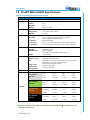
7.0 SmaRT EBU-xH24XF Specifications
Table 8. EBU-xH24XF Base Unit Specifications
Item Description
Power
Vin
+7 to +28VDC
Radio
Frequency
License
Modulation
Antenna
906-924MHz @ 10mW; 2405-2480MHz @ 100mW
Free
DSSS
External or Internal
Environment
Operating Temp
Storage Temp
Humidity
-20°C to 55°C (-4°F to 131°F)
-40°C to 85°C (-40°F to 185°F)
0 to 100%
Indicators (5)
1 – Power
2 – OUT/IN
3 – HEALTH
4 – RF TX/RX
5 – CAN TX/RX
OK when amber
Green – output(s) only active; Red-input(s) only active
Amber – output(s) and input(s) active
Blinking when active
Red – TX only active; Green-RX only active; Amber TX/RX active
Red – TX only active; Green-RX only active; Amber TX/RX active
Enclosure
Dimensions
Durability
Mounting Holes
Weight
6.25” x 8.06” x 2.09” (119mm x 133mm x 36mm)
High Impact Polymer
7.4mm (0.29”) dia.
5.63” center-to-center (143mm center-to-center)
1.45lbs (0.66kg)
Outputs/Inputs
H-Bridge
Active Low (<1V)
FET
Form C Relay
Analog Inputs
Analog Outputs
One @ 4A (M1, M2)
Sixteen (M1−M16) digital inputs
Eight Open Drain @ 2A per channel with current sense (M1−M8)
Eight Open Drain @ 4A per channel (M9−M16)
Two @ 8A per channel (M17, M18)
Four 0-10V (M21−M24)
Two 0-10V (M19−M20)
CAN
Open
Plug B (Black) P1: CANH; P2: CANL; P3: CANTERM
Terminals
Plug A (Gray)
Pins 1-12
1: M1
2: M2
3: M3
4: M4
5: M5
6: M6
7: M7
8: M8
9: +VIN
10: +VIN
11: GND
12: GND
Plug C (Green)
Pins 1-12
1: M9
2: M10
3: M11
4: M12
5: M13
6: M14
7: M15
8: M16
9: +VIN
10: +VIN
11: GND
12: GND
Plug D (Brown)
Pins 1-12
1: M17NC
2: M17COM
3: M17NO
4: M18NC
5: M18COM
6: M18NO
7: M19
8: M20
9: +VDC
10: +VDC
11: GND
12: GND
Plug B (Black)
Pins 1-12
1: CANH
2: CANL
3: CANTERM
4: RS23TX
5: RS232RX
6: M21
7: M22
8: M23
9: M24
10: +VIN
11: GND
12: GND
Note: EBU-xH24XF-CAN units are internally terminated at 1.2k
.Termination can be
removed at the factory.

SmaRT EBU-xH24XF Base Unit
U109.0.0
10
Appendix A: Exposure to Radio Frequency Energy
SmaRT handheld remote units contain radio transceivers. When active, a handheld remote
sends out radio frequency (RF) energy through its internal antenna. The SmaRT handheld
remote complies with limits set by the FCC for operating distance from human tissue.
Appendix B: Agency Identification Label Locations
Figure 10. Agency Identification Label Locations
Appendix C: Antennas, Extensions, and Kits
The Table 9 defines antennas, antenna extensions, and antenna kits available for the EBU-
xH24XF-EXT base units.
Table 9. Compatible EBU-xH-24XF-7773 External Antenna Details
Part
Cervis Ref. No.
900MHz IS BAND Swivel Antenna
BB3-06
2.4GHz IS Band Swivel Antenna
BB3-07
3 ft. antenna extension cable
J5-07
10 ft. antenna extension cable
J5-02
10 ft. antenna cable (J5-02) and external antenna (BB3-06)
EXT-10-900
10 ft. antenna cable (J5-02) and external antenna (BB3-07)
EXT-10-200
3 ft. antenna cable (J5-07) and external antenna (BB3-06)
EXT-3-900
3 ft. antenna cable (J5-07) and external antenna (BB3-07)
EXT-3-200
Note: Only the antenna recommended by Cervis, Inc. is to be used with the SmaRT base
unit.
AGENCY
LABEL

User Manual
2018 Cervis, Inc.
11
Appendix D: EBU-xH24XF Model Specifications
Model
Freq.
RF Pwr
#Ch
Channel Types
Antenna
Input V
EBU-9H24XF-INT-AV4-AO2
900MHz
10mW
24
H-Bridge, FET, Digital In,
Form C Relay
Internal
7 28VDC
EBU-9H24XF-EXT-AV4-AO2
900MHz
10mW
24
H-Bridge, FET, Digital In,
Form C Relay
External
7 28VDC
EBU-2H24XF-INT-AV4-AO2
2.4GHz
100mW
24
H-Bridge, FET, Digital In,
Form C Relay
Internal
7 28VDC
EBU-2H24XF-EXT-AV4-AO2
2.4GHz
100mW
24
H-Bridge, FET, Digital In,
Form C Relay
External
7 28VDC
Note: EBU-xH24XF-CAN units are internally terminated at 1.2k
.Termination can be
removed at the factory.
Appendix E: EBU-xH24XF Cable Harness Options
Table 10. EBU-xH24XF Cable Harnesses
Part #
Connector Colors
Cable
HN-1026
GRAY and GREEN
Two 12-pin connectors; 24 wire; 90 inch total length
Individually numbered 6 inch flying leads
HN-1027
BROWN and BLACK
Two 12-pin connectors; 24 wire; 90 inch total length;
Individually numbered 6 inch flying leads
HN-1016
GRAY
One 12-pin connector; 12 wire; 90 inch total length
Individually numbered 6 inch flying leads
HN-1017
GREEN
One 12-pin connector; 12 wire; 90 inch total length
Individually numbered 6 inch flying leads
HN-1018
BLACK
One 12-pin connector; 12 wire; 90 inch total length
Individually numbered 6 inch flying leads
HN-1019
BROWN
One 12-pin connector; 12 wire; 90 inch total length
Individually numbered 6 inch flying leads

-
 1
1
-
 2
2
-
 3
3
-
 4
4
-
 5
5
-
 6
6
-
 7
7
-
 8
8
-
 9
9
-
 10
10
-
 11
11
-
 12
12
-
 13
13
-
 14
14
-
 15
15
-
 16
16


Cervis SmaRT EBU-9H24XF-INT-AV4-AO2 Manuel utilisateur
- Taper
- Manuel utilisateur
- Ce manuel convient également à
dans d''autres langues
Documents connexes
Autres documents
-
Yamaha ACU16 Manuel utilisateur
-
Digigram IGTES8AESV2 Manuel utilisateur
-
 Digigram AUDIOWAY BRIDGE B3 Manuel utilisateur
-
-
-
Roland M-5000 Le manuel du propriétaire
-
-
-
VINCENT DAC-7 Le manuel du propriétaire
-
AKG Acoustics DMS 700 Le manuel du propriétaire
