
INSTALLATION MANUAL
MULTI INTERFACE UNIT N-8000MI
Thank you for purchasing TOA's Multi Interface Unit.
Please carefully follow the instructions in this manual to ensure long, trouble-free use of your equipment.
TABLE OF CONTENTS
1. SAFETY PRECAUTIONS ............................. 2
2. GENERAL DESCRIPTION ........................... 5
3. FEATURES ................................................... 5
4. SPECIFICATIONS ........................................ 6
5. SYSTEM CONFIGURATION ExAMPLE ..... 7
6. NOMENCLATURE AND FUNCTIONS ......... 8
Front ............................................................. 8
Rear ............................................................... 8
7. INSTALLATION ............................................ 9
7.1. Equipment Rack Mounting ...................... 9
7.2. Desk-Top Installation ............................ 11
7.3. Wall Mounting ....................................... 11
8. WIRING ....................................................... 12
8.1. Connection Diagram ............................. 12
8.2. Type of Cable ....................................... 15
8.3. Connector Connection ......................... 15
9. ACCESSORIES .......................................... 16

2
1. SAFETY PRECAUTIONS
• Beforeinstallationoruse,besuretocarefullyreadalltheinstructionsinthissectionforcorrectandsafe
operation.
• Besuretofollowalltheprecautionaryinstructionsinthissection,whichcontainimportantwarningsand/or
cautionsregardingsafety.
• Afterreading,keepthismanualhandyforfuturereference.
Safety Symbol and Message Conventions
Safetysymbolsandmessagesdescribedbelowareusedinthismanualtopreventbodilyinjuryandproperty
damage which could result from mishandling. Before operating your product, read this manual rst and
understandthesafetysymbolsandmessagessoyouarethoroughlyawareofthepotentialsafetyhazards.
Indicatesapotentiallyhazardoussituationwhich,
if mishandled, could result in death or serious
personalinjury.
WARNING
When Installing the Unit
• Donotexpose the unittorainoranenvironment
whereitmaybesplashedbywaterorotherliquids,
asdoingsomayresultinreorelectricshock.
• Use the unit only with the voltage specied on
theunit.Usingavoltagehigherthanthatwhichis
speciedmayresultinreorelectricshock.
• Do not cut, kink, otherwise damage nor modify
thepowersupplycord.Inaddition,avoidusingthe
powercordincloseproximitytoheaters,andnever
placeheavyobjects--includingtheunititself--on
the power cord, as doing so may result in re or
electric shock.
• Avoid installing or mounting the unit in unstable
locations, such as onarickety table or a slanted
surface. Doing so may result in the unit falling
downandcausingpersonalinjuryand/orproperty
damage.
• Installtheunitonlyinalocationthatcanstructurally
support the weight of the unit and the mounting
bracket. Doing otherwise may result in the unit
falling down and causing personal injury and/or
propertydamage.
When the Unit is in Use
• Should the following irregularity be found during
use,immediatelyswitchoffthepower,disconnect
the power supply plug from the AC outlet and
contactyournearestTOAdealer.Makenofurther
attempttooperatetheunitinthisconditionasthis
maycausereorelectricshock.
· Ifyoudetectsmokeorastrangesmellcomingfrom
the unit.
· Ifwateroranymetallicobjectgetsintotheunit
· Ifthepowersupplycordisdamaged(exposureof
thecore,disconnection,etc.)
· Ifitismalfunctioning(notonesounds.)
• Topreventareorelectricshock,neveropennor
remove the unit case as there are high voltage
components inside the unit. Refer all servicing to
yournearestTOAdealer.
• Donottouchaplugduringthunderandlightning,as
this may result in electric shock.
Indicatesapotentiallyhazardoussituationwhich,
ifmishandled,couldresultinmoderateorminor
personalinjury,and/orpropertydamage.
CAUTION
When Installing the Unit
• Never plug in nor remove the power supply plug
with wet hands, as doing so may cause electric
shock.
• Whenunpluggingthepowersupplycord,besureto
graspthepowersupplyplug;neverpullonthecord
itself. Operating the unit with a damaged power
supplycordmaycauseareorelectricshock.
• Donotblocktheventilationslotsintheunit'scover.
Doingsomaycauseheattobuildupinsidetheunit
andresultinre.
• Besuretofollowtheinstructionsbelowwhenrack-
mountingtheunit.Failuretodosomaycauseare
orpersonalinjury.
· Installtheequipmentrackonastable,hardoor.
Fixitwithanchorboltsortakeotherarrangements
topreventitfromfallingdown.
· To rack-mount the unit, use the supplied rack
mountinghardware.
· Whenconnectingtheunit'spowercordtoanAC
outlet, use the AC outlet with current capacity
allowable to the unit.

3
When the Unit is in Use
• Donotplaceheavyobjectsontheunitasthismay
cause it to fall or break which may result in personal
injury and/or property damage. In addition, the
object itself may fall off and cause injury and/or
damage.
• Donotstandorsiton,norhangdownfromtheunit
asthismaycauseittofalldownordrop,resultingin
personalinjuryand/orpropertydamage.
CONSEILS DE SÉCURITÉ
• Avantl’installation ou l’utilisation, lire attentivement l’ensemble des instructions de cette section pour un
fonctionnement correct et sûr.
• Veilleràrespecterlesprécautionsrecommandéesdanscettesection,laquellecontientdesmisesengarde
et/ouprécautionsimportantesenmatièredesécurité.
• Aprèslecture,conservercemanuelàportéedemainpourconsultationultérieure.
Symboles de sécurité et conventions
Lessymbolesetmessagesdesécuritédécritsci-dessoussontutilisésdanscettenoticepourprévenirtout
dommagecorporeloumatérielpouvantrésulterd’unemauvaiseutilisation.Lireattentivementcettenoticepour
comprendreparfaitementlessymbolesetmessagesdesécuritéandeprévenirtoutrisqueéventuel.
AVERTISSEMENT
Indique une situation risquant d’entraîner des
blessures graves, voire la mort, en cas de
mauvaisemanipulation.
Lors de l’installation de l’appareil
• Nepasexposerl’appareilàlapluieetleprotégerde
toutcontactavecdel’eauoud’autresliquidesan
d’éviterunincendieouuneélectrocution.
• Utilisez l’appareil uniquement avec la tension
spéciéesurlechargeur.L’utilisationd’unetension
supérieure à celle spéciée peut être à l’origine
d’unincendieoud’uneélectrocution.
• Nepascouper,entortiller,modierouendommager
lecordond’alimentation.Enoutre,éviterd’utiliserle
cordond’alimentationàproximitéd’unradiateuret
nejamaisplacerd’objetslourds(ycomprisl’appareil
lui-même) sur le cordon d’alimentation, car ceci
présenteunrisqued’incendieoud’électrocution.
• Évitezd’installeroudemonterl’unitédansunendroit
instable, tel qu’une table bancale ou une surface
inclinée pour prévenir toute chute susceptible
de provoquer une blessure corporelle et/ou une
dégradationmatérielle.
• Installer l’unité dans un endroit structurellement
capabledesoutenirlepoidsdel’appareiletdela
pattedemontage.
L’appareilpourraittomberetprovoquerdesblessures
corporelleset/oudesdommagesmatériels.
Lors de l’installation de l’appareil
• En cas de survenue des irrégularités suivantes
pendantl’utilisation,débrancherimmédiatementla
ficheducordond’alimentationdela prise secteur
et contacter le représentant TOA le plus proche.
Ne pas essayer pas d’utiliser l’appareil dans ces
conditionssouspeinedeprovoquerunincendieou
uneélectrocution.
· Détection de fumée ou d’une odeur inhabituelle
émanantdel’appareil.
· Pénétration d’eau ou d’un objet métallique dans
l’appareil
· Dégradation du cordon d’alimentation (âme du
câbledénudée,déconnexionetc.).
· Dysfonctionnement(absencedetonalité).
• Pourempêcherunincendieouune électrocution,
nejamaisouvrirnineretirerleboîtierdel’appareil,
enraisondelaprésencedepiècesàhautetension.
La maintenance de l’appareil doit être conée au
revendeurTOAleplusproche.
• Ne pas toucher la che du cordon d’alimentation
pendantunorage-Risqued’électrocution.

4
ATTENTION
Indique une situation risquant d’entraîner des
blessuresmoyennementgravesoumineures,et/
oudesdommagesmatériels.
Lors de l’installation de l’appareil
• Ne jamais brancher, ni débrancher la che du
cordon d’alimentation avec les mains mouillées.
Risqued’électrocution.
• Pour débrancher le cordon d’alimentation, veiller
àletenirparsache;nejamaistirerdirectement
le cordon. Utiliser l’appareil avec un cordon
d’alimentation endommagé peut présenter un
risqued’incendieoud’électrocution.
• Ne pas obstruer les fentes de ventilation sur le
capot de l’unité sous peine de provoquer une
accumulationdechaleuràl’intérieurdel’appareil,
pouvantaboutiràunincendie.
• Respecterlesinstructionsci-dessouspourmonter
l’appareilenbâti.Risqued’incendieoudeblessure
corporelle.
· Installerlebâtisurunsolstable.Lexeràl’aide
de boulons d’ancrage ou prendre des mesures
pourempêcherqu’ilnechute.
· Utilisezlematérieldemontagefournipourmonter
l’unitéenbâti.
· Pourbrancherlecordond’alimentationàuneprise
CA,vérierl’intensitémaximaledel’appareil.
Pendant l’utilisation de l’appareil
• Ne pas placer d’objets lourds sur l’appareil sous
peine de le faire tomber ou de le rompre, ce qui
présenteunrisquedeblessurescorporelleset/ou
de dommages matériels. Par ailleurs, l’objet lui-
mêmepeuttomberetprovoquerdesblessureset/
oudégâts.
• Ne pas placer d’objets lourds sur l’appareil sous
peinedelefairetomber,cequiprésenteunrisque
de blessures corporelles et/ou de dommages
matériels.

5
2. GENERAL DESCRIPTION
The N-8000MI is a multi interface unit designed for use with TOA’s packet intercom system (IP network-
compatibleintercomsystem)thatemploysthepacketaudiotechnology*.Connectingthemultiinterfacetoa
localareanetworkpermitstheidealsystemforin-houseorwide-areainformationtransmissionapplications,
suchaspaging,periodicalbroadcasts,andbackgroundmusicbroadcasts,tobebuiltbetweenthemultiinterface
andIPintercomexchangeorothermultiinterfaceunit.Thecontactbridgefunctioncanberealizedthrough
contactinputandoutputcontrol.
*Technologyrelatedtoaudiotransmissionoveranetwork.
Warning
ThisisaclassAproduct.Inadomesticenvironmentthisproductmaycauseradiointerferenceinwhichcase
theusermayberequiredtotakeadequatemeasures.
DESCRIPTION GÉNÉRALE
L’unitéN-8000MIestunemulti-interfaceconçuepouruneutilisationaveclesystèmeintercomparpaquetsde
TOA(systèmeintercomcompatibleavecunréseauIP)utilisantlatechnologiedepaquetsaudio*.
Lebranchementd’unemulti-interfaceàunréseaulocalconstituelesystèmeidéalpourl’installationd’applications
detransmissiond’informationseninterneouauseind’unezonedétendue(notications,appelspériodiques,
diffusiondemusiquedefond)entrelamulti-interfaceetlecentralintercomIPouuneautreunitémulti-interface.
Lafonctiondepontdecontactpeutêtremiseenplaceviauneentréedecontactetuncontrôledelasortie.
*Technologiedetransmissionaudiosurunréseau.
Avertissement
CetéquipementestunproduitdeclasseA.Enenvironnementdomestique,ceproduitpeutprovoquerdes
interférencesradio.
3. FEATURES
• N-8000MIunitscanbedistributedoveradatacommunicationsnetwork.
• Canbeconnectedtoanexistinglocalareanetwork(LAN)orwide-areanetwork(WAN).Theunitcanalsobe
easilyconnectedtober-opticnetworkswithoutrestrictionsonoperatingdistance.
• Thededicatedsoftwareprogramenablescentralizedcontrolwithapersonalcomputer.
• Systemmaintenance(verifyingoperationlogandLinesupervision)canalsobeperformedwithapersonal
computerandInternetbrowser.
• CanbeconnectedtotheExchangeoftheEXES-2000orEXES-6000IntercomSystembyatie-line,orthe
PBXexchangeviatheOD(out-band-dialing)trunk.
• TheunitcaninterlockwithanelectroniclocksystemorCCTVsurveillancesystembywayofcontactinput/
output control function.
CARACTÉRISTIQUES
• LesunitésN-8000MIpeuventêtredistribuéessurunréseaudecommunicationdedonnées.
• Peutêtreconnectéàunréseaulocal(LAN)ouétendu(WAN)existant.L’unitépeutaussifacilementêtre
connectéeàunréseaubreoptique,cequiévitetouterestrictionsurladistancedesstations.
• Logicieldédiépermettantuncontrôlecentraliséàpartird’unPC.
• La maintenance du système (vérication du journal d’opérations et supervision des lignes) peut aussi
intervenirviaunordinateurpersonneletunnavigateurInternet.
• PeutêtreconnectéaucentraldusystèmeintercomEXES-2000ouEXES-6000àl’aided’unelignedejonction,
ouaucentralPBXvialaligneprincipaleàcompositionhorsbande.
• Ilestpossibled’assureruneinterfaceentrel’unitéetunsystèmedeverrouillageélectroniqueouunsystème
decaméradesurveillancevialafonctiondecontrôledel’entrée/sortiedecontact.

6
4. SPECIFICATIONS
NumberofUnits
ConnectabletoLAN: Maximum192(atotalofExchangesandMultiInterfaceUnits)
Speech Link Capacity 2 links
Speech(throughthePBXortie-line): Maximum2links
Audioinput: Maximum2links
Audiooutput: Maximum2links
Note
Theabovelinkscanbesimultaneouslyused.
(Refertothetableinthenextpage.)
Simultaneous access capacity for paging links
Multicastpaging:Maximum2links
Unicastpaging: 1link
PagingZones: Maximum384(With192MultiInterfaceUnits)
PagingZoneViaNetwork: Maximum191(Multicastpaging),Maximum16(Unicastpaging)
BGMInput: Maximum8channels(Numberofinputsperexchange)
PBXInterface: Maximum384(When192MultiInterfaceUnitsareconnected)
Tie-lineInterface: Maximum384(When192MultiInterfaceUnitsareconnected)
ExternalContactOutput: Maximum384(When192MultiInterfaceUnitsareconnected)
ExternalContactInput: Maximum384(When192MultiInterfaceUnitsareconnected)
SystemSettings: Personalcomputersettingusingadedicatedsoftwareprogram(overLAN)
(NetworkRelated)
VoiceDelayTime: 80or320ms,selectable
ConnectionDelayTime: Maximum1second(Whenmulticastpagingismadeto191zones)
UsageBandwidth: Maximum2.08Mbps(oneway)/When16Unicastpagingaremade
Maximum130kbps(two-way)/onecall

7
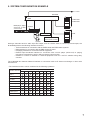
5. SYSTEM CONFIGURATION ExAMPLE
N-8000MI
Contact input
Contact output
(door remote control)
EXES-2000
EXES-6000
PBX
Amplifier
Speaker
To LAN
BGM player, digital
announcer, or other
sound source
Having2channelseachforaudioinputandoutput,and16contactseachforcontrolinputandoutput,the
N-8000MIperformsthefollowinginterfacefunctions*.
• Tie-lineinterfaceforconnectionwiththeEXES-2000andEXES-6000systems.
• PBXinterfaceforconnectionwiththePBXviatheODtrunk.
• PApaginginterfaceforconnectionwithPAequipment
• External input broadcast interface for connection with a music player (chime unit) or paging
microphoneirrespectiveofwithorwithoutremotecontrolfunction.
• Interface to control an indicator or external equipment such as a CCTV's switcher using relay
contacts.
TheN-8000MIalso featuresNetworkinterfaceforconnectionwithanIPintercom exchangeorothermulti
interface unit.
*Theinterfacefunctionscanbecombinedinthefollowing9patterns.
Interface function
Combination pattern
PBX 1
PBX 2
Tie-line 1
Tie-line 2
Audio output 1
Audio output 2
Audio input 1
Audio input 2
Contact IN/OUT
1 2345678
9

8
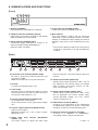
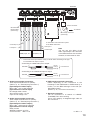
6. NOMENCLATURE AND FUNCTIONS
[Front]
1 2 3 4
5
00-05-F9-FF-00-00
[Rear]
6. Functional earth terminal [SIGNAL GND]
Be sure to ground this terminal unless the unit
connectstoaPBX.
Note: Thisterminalisnotforprotectiveearth.
7. AC inlet
Connectsthesuppliedpowercord.
8. Cord clamp
Passthepowercordthroughthisclamptoensure
thatthe plug does not pull out when the unitis
mountedtoawall.(Refertop.11)
9. Contact input terminals [CONTACT IN]
No-voltagemakecontactinputs.
Short-circuitcurrent:10mA,Open-circuitvoltage:
12V
10. Contact output terminals [CONTACT OUT]
Relay contact outputs.
Withstand voltage: 24 V DC, Control current:
Maximum0.5A
11. Audio input level controls [ExTERNAL
SIGNAL 1, 2]
Use these controls to adjust the audio input
levelsforchannels1and2accordingtotheinput
sources.
12. Audio input terminal [AUDIO IN]
Includesaudioinputs(maximum0dB*
2
,over10
kΩ, balanced) and contact inputs (no-voltage
make contanct, short-circuit current: 10 mA,
open-circuitvoltage:12V).
13. Audio output terminal [AUDIO OUT]
Includesaudiooutputs(maximum0dB*
2
,under
600 Ω, balanced) and control outputs (relay
contact withstand voltage: 24 V DC, control
current:maximum0.5A).
14. PBx interface terminal [PBx IF]
Connects to the Exchange of the EXES-2000
orEXES-6000 systembya tie-line, or the PBX
exchangeviatheOD(out-band-dialing)trunk.
15. Network connection terminal [10/100M]
Connects to a 10BASE-T- or 100BASE-TX-
compatiblenetwork.(EthernetRJ45jack)
*
2
0dB=1V
1. Reset key [RESET]
Pressingthiskeyreactivatestheexchange.
2. LNK/ACT indicator [LNK/ACT] (Green)
Lightswhenconnectedtoanetwork,andashes
whiletransmittingorreceivingdata.
3. Status indicator [STATUS] (Red)
Continuously lights while data is written to an
internalstoragemedium(FlashMemory).
Flashes if there is a failure.
4. Power indicator [POWER] (Green)
Lightswhenpowerissuppliedtotheunit.
5. MAC address
This istheaddress*
1
usedbytheunit.Since the
relationshipofeachexchangelocationtoitsMAC
address is established when setting the network
attributes, keep track of this relationship for later
use.
*
1
Theinherentaddressassignedtoeachnetwork
component, expressed in 12-digit hexadecimal
notation.
ME ME
6 7 8 9 10 11
12
13 14 15

9
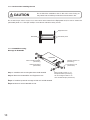
7.1.1. Setting space
Formaintenanceworks,allowmuchspacebetweenthewallandEquipmentrack.
7. INSTALLATION
TheN-8000MIcanbeinstalledinanyofthreeways:Equipmentrackmounting,Desk-topinstallation,andWall
mounting.
7.1. Equipment Rack Mounting
A)ElevatedOperatingAmbient-Ifinstalled inaclosedormulti-unitrackassembly,theoperatingambient
temperatureoftherackenvironmentmaybegreaterthanroomambient.Therefore,considerationshould
begiventoinstallingtheequipmentinanenvironmentcompatiblewiththemaximumambienttemperature
(Tma)specifiedbythemanufacturer.
B)ReducedAirFlow-Installationoftheequipmentinarackshouldbesuchthattheamountofairflowrequired
forsafeoperationoftheequipmentisnotcompromised.
C)MechanicalLoading-Mountingoftheequipmentintherackshouldbesuchthatahazardousconditionis
notachievedduetounevenmechanicalloading.
D)Circuit Overloading - Consideration should be given to the connection of the equipment to the supply
circuitandtheeffectthatoverloadingofthecircuitsmighthaveonovercurrentprotectionandsupplywiring.
Appropriateconsiderationofequipmentnameplateratingsshouldbeusedwhenaddressingthisconcern.
E)ReliableEarthing-Reliableearthingofrack-mountedequipmentshouldbemaintained.Particularattention
shouldbegiventosupplyconnectionsotherthandirectconnectionstothebranchcircuit(e.g.useofpower
strips).”
A)Température ambiante élevée - si l’appareil est installé dans un bâti fermé ou en même temps que
d’autresappareils,latempératureàl’intérieurrisquededevenirsupérieureàlatempératureambiante.Par
conséquent,veilleràinstallerl’équipementdansunenvironnementcompatibleàlatempératureambiante
maximumspéciéeparlefabricant.
B)Débitd’airréduit-L’installationdel’équipementenbâtinedoitpascompromettreledébitd’airnécessaireà
uneutilisationsûredel’équipement.
C)Chargemécanique-Lemontagedel’équipementenbâtinedoitpasentraînerdedangerdûàunesurcharge
mécaniqueinégale.
D)Surcharge du circuit - rester vigilant lors de la connexion de l’équipement au circuit d’alimentation et
aux conséquences d’une surcharge des circuits sur la protection contre les surintensités et les câbles
d’alimentation.Tenircomptedesindicationsdelaplaquenominaledel’appareil.
E)Veiller à toujours garantir l’intégrité de la prise de mise à la terre. Faire particulièrement attention aux
connexionsd’alimentationendehorsdesbranchementsdirectsaucircuitdedérivation(parexempleàl’aide
demultiprises).
TheN-8000MIcanbemountedontheCR-273orCR-413orstandardEIA19”Equipmentrack.
FortheCR-273andCR-413Equipmentrackassembly,readtheinstallationmanualsuppliedwiththerack.
Note
WheninstallingtheN-8000MI,laytheequipmentrackdownface-uptodoinstallationworksafely.
N-8000MI
50 cm
50 cm
1 m
50 cm

10
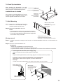
7.1.2. Caution when installing the unit
Perforated panel
Equipment rack
N-8000MI
Donotstackup3unitsormore.If2ormoreunitsaremountedintheEquipmentrack,besuretomountthe
perforatedpanelof1Usize(PF-013B)ormoreaboveandbelowevery2units.
Step 1. I n s t a llt h e rack- mou ntingb r a c ke tto t h eN - 8 0 0 0 MI.
Step 2. MounttheN-8000MIontheEquipmentrack.
Étape 1. Installezlapattedemontageenbâtisurl’unitéN-8000MI.
Étape 2. Montezl’unitéN-8000MIenbâti.
7.1.3. N-8000MI mounting
Montage du N-8000MI
Donotblocktheventilationslotsintheunit’scover.Doingso
maycauseheattobuildupinsidetheunitandresultinre.
CAUTION
Rack mounting screw 5 x 12
with plain washer (accessory)
Rack mounting bracket
(accessory)
Tapping screw 3 x 8
(accessory)
Patte de montage
(accessoire)
Vis de montage en bâti 5 x 12
avec rondelle simple (accessoire)
Vis-taraud 3 x 8
(accessoire)
N-8000MI
1
2

11
7.2. Desk-Top Installation
N-8000MI
Plastic foot
(accessory)
Machine screw M4 x 20
(accessory)
Vis de mécanique M4 x 20
(accessoire)
Pied en plastique
(accessoire)
When installing the N-8000MI on a desk,
secure the supplied plastic feet to the unit’s
bottomusingthesuppliedtappingscrews.
Installation sur un bureau
Pourinstallerl’unitéN-8000MIsurunbureau,
installezlespiedsenplastiquefournissurle
fonddel’appareilàl’aidedesvisfournies.
7.3. Wall Mounting
Step 1. Install the supplied wall-mounting
bracket to the N-8000MI using 4
removedscrewsfromthecase.
N-8000MI
Tapping screw 3 x 8
(removed screws from the case)
Wall mounting bracket
(accessory)
Pattes de montage mural
(accessoire)
Vis-taraud 3 x 8 (vis démontées du boîtier)
Montage mural
Étape 1. Installezlapattedemontagemuralfourniesurl’unitéN-8000MIàl’aidedes4visdémontéesdu
boîtier.
Étape 2. Montezl’unitéN-8000MIaumur.
Remarques
• Utilisezdesvisadaptéesàlastructuredumur.
• L’unitéN-8000MIestlivréeavecdesvisàbois3,5x20.
• Laprisedoitêtreinstalléeàproximitédel’équipementetlachedoitêtrefacilementaccessible.
Cord clamp
Power supply cord
Wood screw
3.5 x 20 (accessory)
Protect against disconnection (Power supply plug)
Wall surface
Unlock cord clamp and run the power supply cord through it.
Note
Keep the cable length between a power supply plug and cord clamp as short as possible.
Protection contre les ruptures d'alimentation (prise d'alimentation)
Déverrouillez le collier à cordon et glissez-y le cordon d'alimentation.
Remarque
Le câble entre la prise d'alimentation et le collier doit être aussi court que possible.
Cordon d'alimentation
Collier du cordon
Surface murale
Vis à bois 3,5 x 20
(accessoire)
Step 2. MounttheN-8000MIonthewall.
Notes
• Use appropriate screws for the construction of wall.
• Woodscrews3.5x20aresuppliedwiththeN-8000MI.
• Thesocket-outletshallbeinstalledneartheequipment
andshallbeeasilyaccessible.

12
8. WIRING
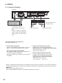
8.1. Connection Diagram
9P removable terminal
plug (accessory)
N-8000MI
Contact input signals Contact output signals
To AC mains or a UPS
(Uninterruptible power supply)*
Note
If there is a danger of lightning
strikes, insert an appropriate
surge arrester into the power
line.
Be sure to ground this
terminal unless the unit
connects to a PBX.
1. Power supply connection
Connect the supplied power supply cord to AC
MainsoraUPS(Uninterruptiblepowersupply).
About power supply cord handling
The supplied power supply cord is designed for
exclusiveusewiththeN-8000MI.
Usethesuppliedpowersupplycordonlywiththe
N-8000MI.
2. Contact input terminal connection
(Refertop.15,"ConnectorConnection.")
[Specification of no-voltage make contact input]
Short-circuitcurrent: 10mA
Open-circuitvoltage:12V
3. Contact output terminal connection
Contactoutputterminalshavenopolarity.
(Refertop.15,"ConnectorConnection.")
[Specification of relay contact output]
Withstandvoltage: 24VDC
Controlcurrent: Max.0.5A
*SelectanappropriateUPStakingintoconsiderationthetotalpowerconsumptionofallsystemcomponents
andtherequiredbackuptime,andalsotherequirementthattheUPSshouldemploytheon-linepowersystem.
Reference
MultiInertfaceUnit:Maximum19W.
8-Port10M/100MSwitchingHub:10W(Differsdependingonproducts.)
[General description of connection]
For cables, refer to p. 15.

13
BGM player, etc.
To the tie-line unit of intercom system
or the PBX's OD trunks
8P removable
terminal plug
(accessory)
Mini-clamp connector
(accessory)
To network
Control input
Control input
Line input *
1
*
1
Connect the Line input cables in a way as shown below according to the type
of connected unit's input or output.
Line input *
1
RJ-45 connector
Amplifier, etc.
N-8000MI
N-8000MI
• Connecting to a balanced input or output
• Connecting to an unbalanced input or output
Connected Unit
Connected Unit
Hot (H)
Hot (H)
Cold (C)
Earth (E)
Earth (E)
N-8000MI
M E M E
4. Audio input terminal connection
Audioinputterminalshavenopolarity.
(Refertop.16,"Terminalplugconnection.")
[Specification of auidio input]
Max.0dB*
2
,over10kΩ,balanced
[Specification of control input]
No-voltagemakecontact
Short-circuitcurrent: 10mA
Open-circuitvoltage:12V
5. Audio output terminal connection
Audiooutputterminalshavenopolarity.
(Refertop.16,"Terminalplugconnection.")
[Specification of auidio output]
Max.0dB*
2
,under600Ω,balanced
[Specification of control output]
Relay contact
Withstandvoltage:24VDC
Controlcurrent: Max.0.5A
6. PBx interface terminal connection
Differs depending on the connections to the
ExchangeoftheEXES-2000orEXES-6000bya
tie-line,ortothePBXexchangeviatheOD(out-
band-dialing)trunk.
(Refertop.15,"ConnectorConnection.")
7. Network connection
Can be connected to a network of 10BASE-
T/100BASE-TXinauto-sensing.
Use a UTP category 5 straight-through cable for
this connection.
*
2
0dB=1V
Note
You can use only either of the
Audio input/output CH1 terminals
orthePBXinterfaceCH1terminal.
Likewise, it is the same for CH2.

14
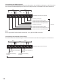
[Connecting to the PBx's OD trunk]
ConnectthePBX'stransmittinglinetotheunit'sRXterminal,andthePBX'sreceivinglinetotheTXterminal.
AlsoconnectthePBX'sM(Mouth)linetotheunit'sE(Ear)terminal,andthePBX'sElinetotheMterminal.
CH1
M
TX RX C
E M
TX RX C
E
CH2
N-8000MI's PBX interface terminal
To PBX OD trunk's transmitting line (T2)
To PBX's ground point
To PBX OD trunk's M and E lines
To PBX OD trunk's receiving line (R2)
2 channels
To PBX OD trunk's transmitting line (T1)
To PBX's ground point
To PBX OD trunk's M and E lines
To PBX OD trunk's receiving line (R1)
[Connecting to the Intercom's Tie-Line Unit]
Connecttheintercom'stransmittinglinetotheunit'sRXterminal,andthereceivinglinetotheTXterminal.
CH1
M
TX RX C
EM
TX RX C
E
CH2
N-8000MI's PBX interface terminal
To Intercom's transmitting
line (T1)
To Intercom's receiving
line (R1)
To Intercom's transmitting
line (T2)
To Intercom's receiving
line (R2)
2 channels
Note
DonotgroundtheFunctionalearthterminal(No.6onp.8)inthisPBXconnection.

15
8.2. Type of Cable
Thetypesofcablesaretobedeterminedaccordingtothefollowingconditions.
• Twistedpairwires(suchasthoseusedforelectronicpush-buttontelephone)aretobeusedforwiringtothe
audioinput/outputterminalsandPBXinterfaceterminal.
• UTP category 5 Straight through cables with RJ45 connector are to be used for wiring the equipments
connectedtoIPnetwork.
• Thenumberofcablespairslaidshouldbedeterminedconsideringthepossibilityoffutureexpansionofthe
system.
• Outdoorwiresshouldbeusedwherewiringpassesthroughinaccessibleareassuchasceilingsorunder
oorswherethemaintenanceisnotperformed.Indoorwiresmayalsobeused,however,incasewherethere
isnoriskofdeteriorationduetoexposuretoheat,etc.
Note
Specificationsrelatedtoeachjunctionareasfollows.
Mini-clampconnector(PBXinterfaceterminal)
Conductordiameter: ø0.4–0.65mm(AWG22–26),Solidwire
Outsidediameter: ø1.05mmorbelow
Removableterminalplug(Controlinput/outputterminalsandaudioinput/outputterminals)
Conductordiameter: ø0.5–2mm(AWG12–24),Solidwire/Strandedwire
8.3. Connector Connection
Mini-clamp connectors for PBX interface terminals and removable terminal plugs for line input and output
terminalsaresuppliedwiththeN-8000MI.
Perform each connector connection as follows.
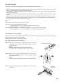
8.3.1. Mini-clamp connector connection
Step 1. Cut off two-cable ends in equal length, and insert them
securelytoacoversection(transparentside)ofthemini-
clamp connector.
Note
Insertthecablewithoutstrippingthecablejacket.
Forcables,refertotheabovesection,TypeofCable.
Step 2. Withapairofpliers,lightlypinchthemini-clampcoverand,
after ensuring that the cable is securely inserted, rmly
squeezeonthecover.
Note
Squeezeonthemini-clampcoveruntilitiscorrectlylocked.
Cover (transparent side)
Cable
N-8000MI
rear panel
Step 3. InsertthewiredplugintotheN-8000MI'ssocketuntilitlocks
into place.

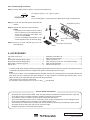
8.3.2. Terminal plug connection
Step 1. Stripacablejacketofapprox.7mmfromthecableend.
7 mm
For cables, refer to p. 15,"TypeofCable."
Note
Donotsolderplateonexposedinnercableswhenusingastrandedwire.
Step 2. Loosentheterminalscrewsandinsertthe
cables.
Step 3. Tighten the terminal screws securely.
Notes
• Tuglightlyonthecabletobesurethatit
doesnotpullfree.Ifthecablepullsfree,
loosen the terminal screw again and
reconnect from Step 2.
• Use the screwdriver appropriatetothe
screwstightenedintotheterminalplug.
Step 4. Insert the wired terminal plug into the
terminal block.
Removable terminal plug
Cable
Removable terminal
block
3
2
4
N-8000MI rear panel
Tighten
ACpowercord(2m) ............................................... 1
CD* ......................................................................... 1
Removableterminalplug(9pins) ........................... 4
Removableterminalplug(8pins) ........................... 2
Mini-clampconnector(2pins) .............................. 10
Plastic foot .............................................................. 4
MachinescrewM4x20 .......................................... 4
Rack mounting bracket ........................................... 2
Tappingscrew3x8 ............................................... 8
Rackmountingscrew5x12withplainwasher ...... 4
Wall mounting bracket ............................................ 2
Woodscrew3.5x20 .............................................. 4
9. ACCESSORIES
* ContainstheN-8000settingsoftwareprogramandtheN-8000seriesinstructionmanual.TheSetupLauncher
isautomaticallystartedwhenthesuppliedCD-ROMisinsertedintothePC'sdrive.
Note
IfyourPC'sCDdriveisnotcompatiblewiththeAutoRunfunction,thesetupguideisnotautomaticallystarted
evenwhentheCDisinserted.Useeither"Explorer"or"MyComputer"toexecutethefollowingfiles,oruse
[Start Run]intheTaskBarandenterthefollowingcommand.
<DrivewhereCDisplaced>\index.html
Forexample,whenplacingtheCDinthe"d"drive, d:\index.html
• DownloadourTOAProductsData,website(http://www.toa-products.com/international/)togetthe
up-to-dateversionforN-8000software,rmware,andInstructionmanuals.
• ThesoftwareversionnumbercanbeconrmedusingtheHelpmenu.
• Thecurrentrmwareversioncanbeconrmedonthesystemmanagementscreendisplayedwhen
the browser establishes the connection to the Multi Interface Unit.
• Theinstructionmanualversionnumbercanbeconrmedbycheckingthepreparationdate(month
andyear)shownatthelowerrightcornerofthelastpage.
Example:PreparedinNovember2004:200411
Version update information
URL:http://www.toa.jp/
133-06-00004-00
-
 1
1
-
 2
2
-
 3
3
-
 4
4
-
 5
5
-
 6
6
-
 7
7
-
 8
8
-
 9
9
-
 10
10
-
 11
11
-
 12
12
-
 13
13
-
 14
14
-
 15
15
-
 16
16


TOA N-8000MI CE Manuel utilisateur
- Taper
- Manuel utilisateur
- Ce manuel convient également à
dans d''autres langues
- English: TOA N-8000MI CE User manual
Documents connexes
-
TOA N-8000DI CE-GB Manuel utilisateur
-
TOA N-8000RS CE-GB Manuel utilisateur
-
Optimus N-8400RS CU Manuel utilisateur
-
-
TOA DA-250D CU Manuel utilisateur
-
-
-
-
-
Optimus N-8010RS CE Manuel utilisateur