
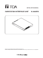
INSTALLATION MANUAL
SUBSTATION INTERFACE UNIT N-8400RS
Thank you for purchasing TOA’s Substation Interface Unit.
Please carefully follow the instructions in this manual to ensure long, trouble-free use of your equipment.

2
TABLE OF CONTENTS
1. SAFETY PRECAUTIONS
............................................................................. 3
2. GENERAL DESCRIPTION .......................................................................... 5
3. FEATURES ............................................................................................................ 5
4. NOMENCLATURE AND FUNCTIONS ................................................. 6
Front ............................................................................................................................. 6
Rear ............................................................................................................................. 6
5. INSTALLATION .................................................................................................. 7
5.1. Equipment Rack Mounting .................................................................................... 7
5.1.1. Set ting s pace ............................................................................................... 8
5.1.2. Caution when installing the unit .................................................................. 8
5.1.3. Mounting on the rack ................................................................................... 9
5.2. Desk-Top Installation ............................................................................................. 9
5.3. Wall Mounting ..................................................................................................... 10
6. WIRING .................................................................................................................. 11
6.1. Connection Diagram ............................................................................................ 11
6.2. Type of Cable ...................................................................................................... 13
6.3. Relations Between Core Diameter of Cable and Maximum Cable Length ......... 13
6.4. Removable Terminal Plug Connection ............................................................... 13
6.5. E-7000TB Terminal Board Wiring ....................................................................... 14
7. ACCESSORIES ................................................................................................. 15
8. OPTIONAL PRODUCT ................................................................................ 15

3
1. SAFETY PRECAUTIONS
• Beforeinstallationoruse,besuretocarefullyreadalltheinstructionsinthissectionforcorrectandsafe
operation.
• Besuretofollowalltheprecautionaryinstructionsinthissection,whichcontainimportantwarningsand/or
cautions regarding safety.
• Afterreading,keepthismanualhandyforfuturereference.
Safety Symbol and Message Conventions
Safety symbols and messages described below are used in this manual to prevent bodily injury and property
damage which could result from mishandling. Before operating your product, read this manual rst and
understand the safety symbols and messages so you are thoroughly aware of the potential safety hazards.
Indicates a potentially hazardous situation which,
if mishandled, could result in death or serious
personal injury.
WARNING
When Installing the Unit
• Do not expose the unit to rain or an environment
where it may be splashed by water or other liquids,
asdoingsomayresultinreorelectricshock.
• Use the unit only with the voltage specied on
the unit. Using a voltage higher than that which is
speciedmayresultinreorelectricshock.
• Do not cut, kink, otherwise damage nor modify
the power supply cord. In addition, avoid using the
power cord in close proximity to heaters, and never
place heavy objects -- including the unit itself -- on
the power cord, as doing so may result in re or
electric shock.
• Avoid installing or mounting the unit in unstable
locations, such as on a rickety table or a slanted
surface. Doing so may result in the unit falling
downandcausingpersonalinjuryand/orproperty
damage.
• Installtheunitonlyinalocationthatcanstructurally
support the weight of the unit and the mounting
bracket. Doing otherwise may result in the unit
falling down and causing personal injury and/or
property damage.
When the Unit is in Use
• Should the following irregularity be found during
use, immediately disconnect the power supply plug
from the AC outlet and contact your nearest TOA
dealer. Make no further attempt to operate the unit
inthisconditionasthismaycausereorelectric
shock.
· If you detect smoke or a strange smell coming
from the unit
· If water or any metallic object gets into the unit
· If the power supply cord is damaged (exposure of
the core, disconnection, etc.)
· If it is malfunctioning (no tone sounds.)
• Topreventareorelectricshock,neveropennor
remove the unit case as there are high voltage
components inside the unit. Refer all servicing to
qualiedservicepersonnel.
• Donotinsertnordropmetallicobjectsorammable
materials in the ventilation slots of the unit's cover,
asthismayresultinreorelectricshock.
• Donottouchaplugduringthunderandlightning,as
this may result in electric shock.
Indicates a potentially hazardous situation which,
if mishandled, could result in moderate or minor
personalinjury,and/orpropertydamage.
CAUTION
When Installing the Unit
• Never plug in nor remove the power supply plug
with wet hands, as doing so may cause electric
shock.
• Whenunpluggingthepowersupplycord,besureto
grasp the power supply plug; never pull on the cord
itself. Operating the unit with a damaged power
supplycordmaycauseareorelectricshock.
• Donotblocktheventilationslotsintheunit'scover.
Doing so may cause heat to build up inside the
unit and result inre. Also, periodically clean the
ventilation slots of dust.
• Besuretofollowtheinstructionsbelowwhenrack-
mountingtheunit.Failuretodosomaycauseare
or personal injury.
· Installtheequipmentrackonastable,hardoor.
Fix it with anchor bolts or take other arrangements
to prevent it from falling down.
· When connecting the unit’s power cord to an AC
outlet, use the AC outlet with current capacity
allowable to the unit.
· The supplied rack-mounting screws can be used
for the TOA equipment rack only. Do not use them
for other racks.
When the Unit is in Use
• Donotplaceheavyobjectsontheunitasthismay
cause it to fall or break which may result in personal
injury and/or property damage. In addition, the
object itself may fall off and cause injury and/or
damage.
• Donotstandorsiton,norhangdownfromtheunit
as this may cause it to fall down or drop, resulting in
personalinjuryand/orpropertydamage.

4
CONSEILS DE SÉCURITÉ
• Avant l’installation ou l’utilisation, lire attentivement l’ensemble des instructions de cette section pour un
fonctionnement correct et sûr.
• Veilleràrespecterlesprécautionsrecommandéesdanscettesection,laquellecontientdesmisesengarde
et/ouprécautionsimportantesenmatièredesécurité.
• Aprèslecture,conservercemanuelàportéedemainpourconsultationultérieure.
Symboles de sécurité et conventions
Lessymbolesetmessagesdesécuritédécritsci-dessoussontutilisésdanscettenoticepourprévenirtout
dommagecorporeloumatérielpouvantrésulterd’unemauvaiseutilisation.Lireattentivementcettenoticepour
comprendreparfaitementlessymbolesetmessagesdesécuritéandeprévenirtoutrisqueéventuel.
Indique une situation risquant d’entraîner des
blessures graves, voire la mort, en cas de
mauvaise manipulation.
Lors de l’installation de l’appareil
• Nepasexposerl’appareilàlapluieetleprotégerde
toutcontactavecdel’eauoud’autresliquidesan
d’éviterunincendieouuneélectrocution.
• Utilisez l’appareil uniquement avec la tension
spéciéesurlechargeur.L’utilisationd’unetension
supérieure à celle spéciée peut être à l’origine
d’unincendieoud’uneélectrocution.
• Nepascouper,entortiller,modierouendommager
lecordond’alimentation.Enoutre,éviterd’utiliserle
cordond’alimentationàproximitéd’unradiateuret
ne jamais placer d’objets lourds (y compris l’appareil
lui-même) sur le cordon d’alimentation, car ceci
présenteunrisqued’incendieoud’électrocution.
• Évitezd’installeroudemonterl’unitédansunendroit
instable, tel qu’une table bancale ou une surface
inclinée pour prévenir toute chute susceptible
de provoquer une blessure corporelle et/ou une
dégradationmatérielle.
• Installer l’unité dans un endroit structurellement
capable de soutenir le poids de l’appareil et de la
patte de montage.
L’appareil pourrait tomber et provoquer des blessures
corporelleset/oudesdommagesmatériels.
Pendant l’utilisation de l’appareil
• En cas de survenue des irrégularités suivantes
pendantl’utilisation,débrancherimmédiatementla
fiche du cordon d’alimentation de la prise secteur
et contacter le représentant TOA le plus proche.
Ne pas essayer pas d’utiliser l’appareil dans ces
conditions sous peine de provoquer un incendie ou
uneélectrocution.
· Détection de fumée ou d’une odeur inhabituelle
émanantdel’appareil.
· Pénétration d’eauou d’un objet métallique dans
l’appareil
· Dégradation du cordon d’alimentation (âme du
câbledénudée,déconnexionetc.).
· Dysfonctionnement(absencedetonalité).
• Pourempêcherunincendie ouuneélectrocution,
ne jamais ouvrir ni ne retirer le boîtier de l’appareil,
enraisondelaprésencedepiècesàhautetension.
Lamaintenancedel’appareildoitêtreconéeàun
technicienaprès-ventequalié.
• Nepasinsérernilaissertomberd’objetsmétalliques
oudematériauxinammablesdansleséventsde
ventilation du capot de l’appareil sous peine de
provoquerunincendieouuneélectrocution.
• Ne pas toucher la che du cordon d’alimentation
pendantunorage-Risqued’électrocution.
ATTENTION
Indique une situation risquant d’entraîner des
blessuresmoyennementgravesoumineures,et/
oudesdommagesmatériels.
Lors de l’installation de l’appareil
• Ne jamais brancher, ni débrancher la che du
cordon d’alimentation avec les mains mouillées.
Risqued’électrocution.
• Pour débrancher le cordon d’alimentation, veiller
àletenirparsache;nejamaistirerdirectement
le cordon. Utiliser l’appareil avec un cordon
d’alimentation endommagé peut présenter un
risqued’incendieoud’électrocution.
• Nepasobstruerlesfentesdeventilationsurlecapot
del’unitésouspeinedeprovoqueruneaccumulation
dechaleuràl’intérieurdel’appareil,pouvantaboutir
àunincendie.Nettoyerrégulièrementlesencoches
de ventilation.
AVERTISSEMENT

5
• Respecterlesinstructionsci-dessouspourmonter
l’appareilenbâti.Risqued’incendieoudeblessure
corporelle.
· Installerlebâtisurunsolstable.Lexeràl’aide
de boulons d’ancrage ou prendre des mesures
pourempêcherqu’ilnechute.
· Pourbrancherlecordond’alimentationàuneprise
CA,vérierl’intensitémaximaledel’appareil.
· Les vis de montage en bâti fournies peuvent
seulementêtreutiliséespourlebâtidel’équipement
TOA.Nepaslesutiliserpourd’autresbâtis.
Pendant l’utilisation de l’appareil
• Ne pas placer d’objets lourds sur l’appareil sous
peine de le faire tomber ou de le rompre, ce qui
présenteunrisquedeblessurescorporelleset/ou
de dommages matériels. Par ailleurs, l’objet lui-
mêmepeuttomberetprovoquerdesblessureset/
oudégâts.
• Ne pas placer d’objets lourds sur l’appareil sous
peinedelefairetomber,cequiprésenteunrisque
de blessures corporelles et/ou de dommages
matériels.
2. GENERAL DESCRIPTION
TOA'sN-8400RSisSubstationinterfaceunitusedfortheN-8000SeriesPacketIntercomSystem(IPnetwork
compatible intercom) employing packet audio technology*.
Up to 16 substations can be connected using two pairs of twisted pair cables.
ThemaximumnumberofLAN-connectableN-8000systemcomponentssuchasexchanges,IPstations,and
various kinds of interface units is 192 in total.
ConnectingtheunittotheLANpermitsthesubstationtoreceivepagingcallsandmakecallstoboththemaster
station connected to the IP intercom exchange and the IP master station.
* Technology related to audio transmission over a network
Warning
This is a class A product. In a domestic environment this product may cause radio interference in which case
the user may be required to take adequate measures.
DESCRIPTION GÉNÉRALE
L’unitéN-8400RSdeTOAestl’interfacedesous-stationutiliséepourlesystèmedepaquetintercomdesséries
N-8000 (intercom compatible avecun réseau IP) utilisant une technologie de paquets audio*. Ellepermet
debrancherjusqu'à16sous-stationsàl'aidededeuxpairesdecâblesàpairetorsadée.Ilestpossiblede
connecterjusqu'à192composantsdusystèmeN-8000compatibleLAN:centraux,stationsIPetdifférents
typesd'interfaces.Lebranchementdel'unitéauréseaulocalpermetàlasous-stationderecevoirdesappels
denoticationetd'émettredesappelsverslastationprincipaleconnectéeaucentralintercomIPetversla
station principale IP.
*Technologiedetransmissionaudiosurunréseau
Avertissement
CetéquipementestunproduitdeclasseA.Enenvironnementdomestique,ceproduitpeutprovoquerdes
interférencesradio.
3. FEATURES
• Exchanges,IPstationsandvariouskindsofinterfaceunitscanbeconnectedoveradatacommunications
network.
• Canbeconnectedtoanexistinglocalareanetwork(LAN)orwide-areanetwork(WAN).
• Thededicatedsoftwareprogramenablescentralizedcontrolwithapersonalcomputer.
• Systemmaintenance(verifyingoperationlogandLinesupervision)canalsobeperformedwithapersonal
computer and Internet browser.
CARACTÉRISTIQUES
• Unréseaudecommunicationdedonnéespermetlaconnexiondecentraux,destationsIPetdedifférents
types d’interfaces.
• Peutêtreconnectéàunréseaulocal(LAN)ouétendu(WAN)existant.
• Logicieldédiépermettantuncontrôlecentraliséàpartird’unPC.
• La maintenance du système (vérication du journal d’opérations et supervision des lignes) peut aussi
intervenir via un ordinateur personnel et un navigateur Internet.

6
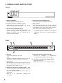
4. NOMENCLATURE AND FUNCTIONS
[Front]
1 2 3 4
5
1. Reset key [RESET]
Pressing this key reactivates the unit.
2. LNK/ACT indicator [LNK/ACT] (Green)
Lightswhenconnectedtoanetwork,andashes
while transmitting or receiving data.
3. Status indicator [STATUS] (Red)
Continuously lights while data is written to an
internal storage medium (FlashMemory), and
ashes to indicate such unit malfunctions as
internal cooling fan failure.
4. Power indicator [POWER] (Green)
Lights when power is supplied to the unit.
5. MAC address
This is the MAC address* for the unit. Since the
relationship of each unit location to its MAC address
is established when setting the network attributes,
keep track of this relationship for later use.
* The inherent address assigned to each network
component, expressed in 12-digit hexadecimal
notation.
[Rear]
6 7 8
10
9
6. AC inlet
Connect the supplied power cord.
Note
If there is a danger of lightning strikes, insert an
appropriate surge arrester into the power line.
7. Cord clamp
Pass the power cord through this clamp to ensure
that the plug does not pull out when the unit is
mounted to a wall. (Refer to p. 10.)
8. Substation connection terminals [LINE 1 – 16]
Connect substations to these terminals using two
pairs of twisted pair cables.
Use the supplied removable terminal plug for
connection.
Refer to p. 13 "Removable Terminal Plug
Connection."
9. Network connection terminal [LAN]
Connects a 10BASE-T- or 100BASE-TX-
compatible network. (Ethernet RJ-45 jack)
10. Functional earth terminal [SIGNAL GND]
Ground this terminal.
Note: This terminal is not for protective earth.

7
5. INSTALLATION
TheN-8400RScanbeinstalledinanyofthreeways:Equipment rack mounting, Desk-top installation, and Wall
mounting.
INSTALLATION
L’unitéN-8400RSpeutêtreinstalléedetroismanières:Montageenbâti,Montagesurbureau,etMontage
mural.
5.1. Equipment Rack Mounting
A) Elevated Operating Ambient - If installed in a closed or multi-unit rack assembly, the operating ambient
temperature of the rack environment may be greater than room ambient. Therefore, consideration should
be given to installing the equipment in an environment compatible with the maximum ambient temperature
(Tma)speciedbythemanufacturer.
B)ReducedAirFlow-Installationoftheequipmentinarackshouldbesuchthattheamountofairowrequired
for safe operation of the equipment is not compromised.
C) Mechanical Loading - Mounting of the equipment in the rack should be such that a hazardous condition is
not achieved due to uneven mechanical loading.
D) Circuit Overloading - Consideration should be given to the connection of the equipment to the supply
circuit and the effect that overloading of the circuits might have on overcurrent protection and supply wiring.
Appropriate consideration of equipment nameplate ratings should be used when addressing this concern.
E) Reliable Earthing - Reliable earthing of rack-mounted equipment should be maintained. Particular attention
should be given to supply connections other than direct connections to the branch circuit (e.g. use of power
strips)."
TheN-8400RScanbemountedontheCR-273,CR-413,orstandardEIA19"Equipmentrack.
For the CR-273 and CR-413 Equipment rack assembly or BU-412 Blower unit installation, read the installation
manual supplied with the rack.
Note
WheninstallingtheBlowerunitandN-8400RS,laytheequipmentrackdownface-uptodoinstallationwork
safely.SincetheBlowerunitisinstalledfromtheinsideoftherack,besuretoinstallitrst,beforemounting
the other components.
Montage en bâti
A)Température ambiante élevée - si l’appareil est installé dans un bâti fermé ou en même temps que
d’autresappareils,latempératureàl’intérieurrisquededevenirsupérieureàlatempératureambiante.Par
conséquent,veilleràinstallerl’équipementdansunenvironnementcompatibleàlatempératureambiante
maximumspéciéeparlefabricant.
B)Débitd’airréduit-L’installationdel’équipementenbâtinedoitpascompromettreledébitd’airnécessaireà
uneutilisationsûredel’équipement.
C)Chargemécanique-Lemontagedel’équipementenbâtinedoitpasentraînerdedangerdûàunesurcharge
mécaniqueinégale.
D)Surcharge du circuit - rester vigilant lors de la connexion de l’équipement au circuit d’alimentation et
aux conséquences d’une surcharge des circuits sur la protection contre les surintensités et les câbles
d’alimentation. Tenir compte des indications de la plaque nominale de l’appareil.
E)Veiller à toujours garantir l’intégrité de la prise de mise à la terre. Faire particulièrement attention aux
connexionsd’alimentationendehorsdesbranchementsdirectsaucircuitdedérivation(parexempleàl’aide
de multiprises).
L’unitéN-8400RSpeutêtremontéeenbâtiCR-273,CR-414ouEIA19”standard.Pourinstallerl’équipement
enbâtiCR-273etCR-413,ouinstallerleventilateurBU-412,reportez-vousaumanueld’installationfourniavec
lebâti.
Remarque
Pourinstallerleventilateuretl’unitéN-8400RS,posezlebâtiàplatpoureffectuerl’installationentoutesécurité.
Leventilateurétantinstallédepuisl’intérieurdubâti,soninstallationdoitinterveniravantcelledetouslesautres
composants.

8
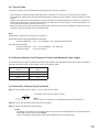
5.1.1. Setting space
For maintenance works, allow much space between the
wall and Equipment rack.
Espace à prévoir
Prévoyez un espace sufsant entre le mur et le bâti en
prévisiondestravauxdemaintenance.
N-8400RS
50 cm
50 cm
1 m
50 cm
Perforated panels
Equipment rack
N-8400RS
Bâti
Panneau perforé
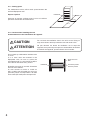
5.1.2. Caution when installing the unit
Avertissement lors de l’installation de l’appareil
Do not stack up 3 Substation interface units
or more.
If 2 or more units are mounted in the
Equipment rack, be sure to mount the
perforated panel of 1-unit size (PF-013B) or
more above and below every 2 units.
N’empilezpasplusde3unitésd’interface
avec les sous-stations.
Si vous montez au moins 2 unités en
bâti, n’oubliez pas d’installer au moins un
panneau perforé correspondant à la taille
d’uneunité(PF-013B)entrechaqueunité.
Do not block the ventilation slots in the unit’s cover. Doing so
maycauseheattobuildupinsidetheunitandresultinre.
CAUTION
Ne pas obstruer les fentes de ventilation sur le capot de
l’appareil, sous peine de provoquer une accumulation de chaleur
àl’intérieurdel’appareil,pouvantaboutiràunincendie.
ATTENTION

9
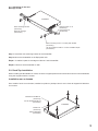
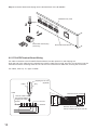
5.1.3. Mounting on the rack
Montage en bâti
Step 1. Installtherack-mountingbrackettotheN-8400RS.
Step 2. MounttheN-8400RSontheEquipmentrack.
Étape 1. Installezlapattedemontageenbâtisurl’unitéN-8400RS.
Étape 2. Montezl’unitéN-8400RSenbâti.
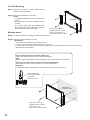
5.2. Desk-Top Installation
WheninstallingtheN-8400RSonadesk,securethesuppliedplasticfeettothebottomsurfaceoftheN-8400RS
using the supplied machine screws.
Installation sur un bureau
Pourinstallerl’unitésurunbureau,installezlespiedsenplastiquefournissurlefonddel’appareilàl’aidedes
vis fournies.
N-8400RS
Rack mounting screw 5 x 12 with plain washer
(accessory)
Rack mounting bracket
(accessory)
Tapping screw 3 x 8
(accessory)
Patte de montage
(accessoire)
Vis-taraud 3 x 8
(accessoire)
1
2
(accessoire)
Vis de montage en bâti 5 x 12 avec rondelle simple
Plastic foot
(accessory)
Machine screw M3 x 8
(accessory)
Vis de mécanique M3 x 8
(accessoire)
Pied en plastique
(accessoire)
N-8400RS

10
5.3. Wall Mounting
Step 1. Install the optional YC-850 Wall-mounting
brackettotheN-8400RS.
Step 2. MounttheN-8400RSonthewall.
Notes
• Useappropriatescrewsfortheconstruction
of wall.
• Woodscrews3.5x20aresuppliedwiththe
YC-850.
• The socket-outlet shall be installed near
the equipment and the plug (disconnecting
device) shall be easily accessible.
Montage mural
Étape 1. InstallezlapattedemontageenbâtiYC-850fournie.
Étape 2. Montezl’unitéN-8400RSaumur.
Remarques
• Utilisezdesvisadaptéesàlastructuredumur.
• L’unitéYC-850estlivréeavecdesvisàbois3,5x20.
• Laprisedoitêtreinstalléeàproximitédel’équipementetlache(dispositifdedéconnexion)doit
êtrefacilementaccessible.
N-8400RS
Machine screw M3 x 6
(supplied with the YC-850)
Vis de mécanique M3 x 6
(fournie avec l'unité YC-850)
Wall surface
Wood screw 3.5 x 20
(supplied with the YC-850)
Protect against disconnection (Power supply plug)
Power supply cord
Cordon d'alimentation
Vis à bois 3,5 x 20
(fournie avec l'unité YC-850)
Surface murale
Cord clamp
Collier du cordon
Unlock cord clamp and run the power supply cord through it.
Note
Keep the cable length between a power supply plug and cord clamp as short as possible.
Protection contre les ruptures d'alimentation (prise d'alimentation)
Déverrouillez le collier à cordon et glissez-y le cordon d'alimentation.
Remarque
Le câble entre la prise d'alimentation et le collier doit être aussi court que possible.

11
6. WIRING
6.1. Connection Diagram
4P removable terminal plug
(supplied with the N-8400RS)
N-8400RS Substation interface unit
To AC mains or a UPS
(Uninterruptible power supply system)*
Note
RS-450, RS-460,
RS-470, or RS-480
RJ-45 connector
To network
16 lines
To line 3 (orange)
Two pairs of twisted pair cable
To line 4 (yellow)
To line 1 (brown)
To line 2 (red)
Be sure to ground.
1 2 3
If there is a danger of lightning strikes,
insert an appropriate surge arrester
into the power line.
Tips
For more information on the RS-450, RS-460,
RS-470, and RS-480, please refer to their respective
installation manuals.
•
•
This figure represents the RS-450.
[General description of connection]
For cables, refer to p. 13.
1. Power supply connection
Connect the supplied power supply cord to AC
Mains or a UPS (Uninterruptible power supply).
About power supply cord handling
The supplied power supply cord is designed for
exclusiveusewiththeN-8400RS.
Neveruseitwithotherequipment.
2. Substation Connections
(Refer to p. 13 "Removable Terminal Plug
Connection.")
3. Network connection
Can be connected to a network of 10BASE-
T/100BASE-TXinauto-sensing.
Use a straight through cable of UTP category 5 or
more for this connection.
* Select an appropriate UPS taking into consideration the total power consumption of all system components
and the required backup time. On-line uninterruptible power supply (UPS) is recommended.
Reference
SubstationinterfaceunitN-8400RS:35W(rated)forCEversion,31W(rated)forCUversion
8-Port10M/100MSwitchingHub:Approx.10W(Differsdependingonproducts.)

12
CÂBLAGES
Schéma de branchements
Prise 4P amovible
(fournie avec l'unité N-8400RS)
Unité d'interface de sous-station N-8400RS
RS-450, RS-460,
RS-470, ou RS-480
Connecteur RJ45
16 lignes
1 2 3
Ne pas oublier la mise à la terre.
Vers le réseau
Vers prise secteur CA
(ou système d'alimentation sans interruption)*
Remarque
Installez un parafoudre sur la ligne électrique
pour protéger votre installation.
Vers ligne 1 (marron)
Vers ligne 2 (rouge)
Vers ligne 3 (orange)
Vers ligne 4 (jaune)
Conseils
• Cette figure représente l'unité RS-450.
• Pour de plus amples informations sur les unités
RS-450, RS-460, RS-470 et RS-480, reportez-vous
aux manuels d'installation correspondants.
Deux paires de câbles
à paire torsadée
[Description générale des branchements]
Pourlescâbles,reportez-vousàlapage13.
1. Branchement à l'alimentation
Branchez le cordon d'alimentation fourni sur la
prise secteur CA (ou un système d'alimentation
sans interruption).
À propos du maniement du cordon d'alimentation
Le cordon d'alimentation fourni est exclusivement
destinéàuneutilisationavecl'unitéN-8400RS.
Nejamaisl'utiliseravecunautreéquipement.
2. Branchement des sous-stations
(Reportez-vous à la page 13, "Removable
TerminalPlugConnection.”)
3. Connexion réseau
Peutêtreconnectéàunréseau10BASET/100BASE-
TXenauto-détection.
UtiliseruncâbledroitUTPdecatégorie5ouplus
pour ce branchement.
*Choisissezlesystèmed'alimentationsanscoupureadaptéenprenantencomptelaconsommationélectrique
totale de l'ensemble des composants du système ainsi que la durée de récupération nécessaire. Nous
recommandonsunsystèmed'alimentationsanscoupureenfonctionnementcontinu.
Référence
Interfacepoursous-stationN-8400RS:35W(nominal)pourlaversionCE,31W(nominal)pourlaversionCU
.
8port10M/100Mconcentrateurdecommutation:Environ10W(enfonctiondesproduits.)

13
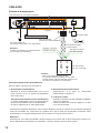
6.4. Removable Terminal Plug Connection
Step 1. Strip a cable jacket of approx. 7 mm to expose inner cable.
Step 2. Loosen the terminal screws and insert the cables.
Step 3. Tighten the terminal screws securely.
Notes
• Tuglightlyonthecabletobesurethatitdoesnotpullfree.Ifthecablepullsfree,loosentheterminal
screw again and reconnect from Step 2.
• Usethescrewdriverappropriatetothescrewstightenedintotheterminalplug.
7 mm
For cables, refer to above "Type of Cable."
Note
Do not solder on exposed inner cables when using a stranded wire.
6.2. Type of Cable
The types of cables are to be determined according to the following conditions.
• UTPCategory5straightthroughcablewithRJ45connectorsistobeusedforconnectingtoIPnetwork.
• Thenumberofcablespairslaidshouldbedeterminedconsideringthepossibilityoffutureexpansionofthe
system.
• Outdoorwiresshouldbeusedwherewiringpassesthroughinaccessibleareassuchasatticsorunderoors
where the maintenance is not performed. Indoor wires may also be used, however, in case where there is no
risk of deterioration due to exposure to heat, etc.
• Makesurethatthetwopairsoftwistedpaircablesareusedforwiringfromthesubstationinterfaceunittothe
substation (RS-450, RS-460, RS-470, and RS-480).
Note
Specicationsrelatedtoconnectionsareasfollows.
Removableterminalplug(N-8400RSlineterminal)
Conductordiameter: ø0.5–2mm(AWG12–24),Solidwire/Strandedwire
Clip terminal (E-7000TB)
Conductordiameter: ø0.4–0.8mm(AWG20–26),Solidwire
Outsidediameter: ø0.5mmorbelow
6.3. Relations Between Core Diameter of Cable and Maximum Cable Length
For the maximum (two pairs of twisted pair) cable length between the substation interface unit and the substation
(RS-450, RS-460, RS-470, and RS-480), refer to the following table.
Conductor diameter
(mm)
Maximum cable length
(km)
ø0.5 1.0
ø0.65 1.5
ø0.9 2.0

14
Step 4. InsertthewiredterminalplugintotheterminalblockoftheN-8400RS.
3
2
4
Tighten
Removable terminal plug
(accessory)
Removable terminal block
N-8400RS rear panel
6.5. E-7000TB Terminal Board Wiring
For cable connection to the E-7000TB Terminal Board, use the optional YC-105 Clipping tool.
Hooktheendofthecableontotheterminaland,withthecableendinhand,presstheYC-105downontothe
terminal from above. Pressing down the YC-105 tool cuts off the excess cable end, securing the connection.
For cables, refer to p. 13, "Type of Cable."
Terminal board E-7000TB
Cable
Hook the cable onto
the terminal without
stripping the cable
sheath.
Yellow Gray
Clipping tool YC-105
(Optional)
Bind the cables using the cord
clamps supplied with the E-7000TB.
Cut end
Terminal

15
7. ACCESSORIES
*ContainstheN-8000SettingsoftwareprogramandtheN-8000seriesinstructionmanual.TheSetupLauncher
is automatically started when the supplied CD-ROM is inserted into the PC's drive.
Note
If your PC's CD drive is not compatible with the AutoRun function, the setup guide is not automatically started
evenwhentheCDisinserted.Useeither"Explorer"or"MyComputer"toexecutethefollowingles,oruse
[Start
Run] in the Task Bar and enter the following command.
<Drive where CD is placed> \index.html
For example, when placing the CD in the "d" drive, d:\index.html
AC power cord (2 m) .............................................. 1
CD* (for PC setting, maintenance use) ................. 1
Removable terminal plug (4 pins) ........................ 16
Plastic foot ............................................................. 4
Machine screw M3 x 8 ........................................... 4
Rack mounting bracket .......................................... 2
Tapping screw 3 x 8 .............................................. 8
Rack mounting screw 5 x 12 with plain washer
............. 4
Cordon d’alimentation CA (2 m) ............................ 1
CD*(pourleparamétrageduPC,
destinéauservicedemaintenance) ........... 1
Prise amovible (4 broches) .................................. 16
Pied en plastique ................................................... 4
VisdemécaniqueM3x8 ...................................... 4
Pattes de montage ................................................ 2
Vis-taraud3x8 ..................................................... 8
Visdemontageenbâti5x12
avec rondelle simple
.................................... 4
* Contient le logicieldeparamétragedel’unitéN-8000ainsiquelanoticederéférencedelasérieN-8000.
Leprogrammedelancementdelacongurationdémarreautomatiquementlorsdel’insertionduCD-ROM
fourni dans le lecteur.
Remarque
SilelecteurdeCDdevotrePCn’estpascompatibleaveclafonctiond’exécutionautomatique,l’assistant
decongurationnes’ouvrepasautomatiquementlorsdel’insertionduCD.Recherchezleschierssuivants
dans l’Explorateur Windows,Poste de travailou saisissez la commande ci-dessous après avoir lancé la
fonction [Lancer
L’exécution]delaBarredestâches.
<LecteurdanslequelleCDaétéinséré>\index.html.
Par exemple, pour l'insertion du CD dans le lecteur D d:\index.html
8. OPTIONAL PRODUCT
Wallmountingbracket: YC-850
PRODUIT EN OPTION
Pattesdemontagemural: YC-850
ACCESSOIRES

Traceability Information for Europe
RenseignementsrelatifsàlatraçabilitéenEurope
Manufacturer:
Fabricant:
TOA Corporation
7-2-1,Minatojima-Nakamachi,Chuo-ku,Kobe,Hyogo,
Japan
Authorizedrepresentative:
Représentantagréé:
TOAElectronicsEuropeGmbH
Suederstrasse282,20537Hamburg,
Germany
URL:http://www.toa.jp/
133-06-00011-00
• DownloadourTOAProductsData,website(http://www.toa-products.com/international/)togetthe
up-to-dateversionforN-8000software,rmware,andInstructionmanuals.
• Thecurrentrmwareversioncanbeconrmedonthesystemmanagementscreendisplayedwhen
the browser establishes the connection to the Substation interface unit.
• ThesoftwareversionnumbercanbeconrmedusingtheHelpmenu.
• Theinstructionmanualversionnumbercanbeconrmedbycheckingthepreparationdate(month
and year) shown at the lower right corner of the last page.
Example:PreparedinSeptember2009:200909
Version update information
• Les ches techniques des produits TOA sont disponibles au téléchargement sur le site web à
l’adresse http://www.toa-products.com/international/ où voustrouverezégalement lesversions les
plusrécentesdulogiciel,dumicroprogrammeetdesnoticesderéférencedel’unitéN-8000.
• Pourvérierlaversiondumicroprogramme,consultezl’écrand’administrationdusystèmequis’afche
lorsquelenavigateurseconnecteàl’interfacedelasous-station.
• LaversiondulogicielestindiquéedanslemenuAide.
• Lenumérodeversiondelanoticederéférenceestindiquédanslecoinintérieurdroitdeladernière
pageetcorrespondàladatedesapublication(moisetannée).
Exemple:Publiéenseptembre2009:200909.
Informations sur les versions de mise à jour
-
 1
1
-
 2
2
-
 3
3
-
 4
4
-
 5
5
-
 6
6
-
 7
7
-
 8
8
-
 9
9
-
 10
10
-
 11
11
-
 12
12
-
 13
13
-
 14
14
-
 15
15
-
 16
16


Optimus N-8400RS CU Manuel utilisateur
- Taper
- Manuel utilisateur
- Ce manuel convient également à
dans d''autres langues
- English: Optimus N-8400RS CU User manual