Empire Console Vented Room Heaters (RH25/35) Le manuel du propriétaire
- Catégorie
- Cheminées
- Taper
- Le manuel du propriétaire
Ce manuel convient également à

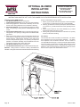
WARNING
If not installed, operated and maintained
in accordance with the manufacturer's
instructions, this product could expose you
to substances in fuel or from fuel combustion
which can cause death or serious illness.
WARNING
FIRE OR EXPLOSION HAZARD
If the information in these instructions is
not followed exactly, a re or explosion may
result causing property damage, personal
injury or loss of life.
— Do not store or use gasoline or other
ammable vapors and liquids in the
vicinity of this or any other appliance.
— WHAT TO DO IF YOU SMELL GAS
• Do not try to light any appliance.
• Do not touch any electrical switch;
do not use any phone in your building.
• Leave the building immediately.
• Immediately call your gas supplier
from a neighbor’s phone. Follow
the gas supplier’s instructions.
• If you cannot reach your gas
supplier, call the re department.
— Installation and service must be
performed by a qualied installer,
service agency or the gas supplier.
INSTALLER:
Leave this manual with the appliance.
CONSUMER:
Retain this manual for future reference.
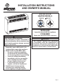
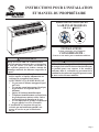
VENTED ROOM
HEATER MODELS
RH-25-8 RH-35-7
INSTALLATION INSTRUCTIONS
AND OWNER'S MANUAL
Page 1

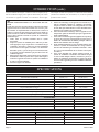
TABLE OF CONTENTS
IMPORTANT SAFETY INFORMATION ........................................................................................................................3
SAFETY INFORMATION FOR USERS OF PROPANE GAS .......................................................................................4
INTRODUCTION..................................................................................................................................................... 5 - 6
SPECIFICATIONS ........................................................................................................................................................6
GAS SUPPLY ................................................................................................................................................................7
CLEARANCES ..............................................................................................................................................................8
VENTING ......................................................................................................................................................................8
VENTING GUIDELINES ...............................................................................................................................................9
VENT SAFETY SHUTOFF SYSTEM ..........................................................................................................................10
REVERSIBLE VERTICAL OR HORIZONTAL DRAFT DIVERTER .............................................................................10
THERMOSTAT OPERATION ......................................................................................................................................10
LIGHTING INSTRUCTIONS .......................................................................................................................................11
PILOT FLAME CHARACTERISTICS ..........................................................................................................................12
MAIN BURNER FLAME CHARACTERISTICS ...........................................................................................................12
MAINTENANCE ..........................................................................................................................................................13
TROUBLESHOOTING ................................................................................................................................................13
PARTS LIST ................................................................................................................................................................14
PARTS VIEW ..............................................................................................................................................................15
OPTIONAL BLOWER INSTALLATION INSTRUCTIONS ................................................................................... 16 - 17
MASTER PARTS DISTRIBUTOR LIST .......................................................................................................................18
HOW TO ORDER REPAIR PARTS .............................................................................................................................18
WARRANTY ................................................................................................................................................................19
SECTION PAGE
38151-4-0320Page 2

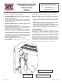
• Due to high temperatures, the room heater should
be located out of trafc and away from furniture
and draperies.
• Children and adults should be alerted to the hazards
of high surface temperature and should stay away
to avoid burns or clothing ignition.
• Young children should be carefully supervised when
they are in the same room as the room heater.
• Clothing or other ammable material should not be
placed on or near the room heater.
• Due to high surface temperatures, keep children,
clothing and furniture away.
• Keep burner and control compartment clean.
• Installation and repair should be done by a QUALI-
FIED SERVICE PERSON. The room heater should
be inspected before use and at least annually by a
qualied service person. More frequent cleaning
may be required due to excessive lint from carpet-
ing, bedding material, etc. It is imperative that
control compartments, burners and circulating air
passageways of the room heater be kept clean.
• DO NOT put anything around the heater that will
obstruct the ow of combustion and ventilation air.
See clearances.
• DO keep the appliance area clear and free from
combustible material, gasoline and other ammable
vapors and liquids.
• DO examine venting system periodically. Clean and
replace damaged parts. Examinations should be
made at the start of the heating season and also in
mid heating season under average conditions.
• DO examine burners periodically. Clean and replace
damaged parts.
• DO NOT use this heater if any part has been under
water. Immediately call a qualied service techni-
cian to inspect the heater and to replace any part
of the control system and any gas control which
has been under water.
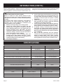
THIS IS A HEATING APPLIANCE
DO NOT OPERATE THIS APPLIANCE WITHOUT FRONT PANEL INSTALLED.
Attention: During operation of vented room heater the gasket for observation hole cover, observation hole cover and
cover plate for observation hole cover must be attached to combustion chamber and secured with two (2) wing nuts.
IMPORTANT SAFETY INFORMATION
38151-4-0320 Page 3

Some people cannot smell well. Some people cannot smell
the odor of the chemical put into the gas. You must nd out if
you can smell the odorant in propane. Smoking can decrease
your ability to smell. Being around an odor for a time can affect
your sensitivity or ability to detect that odor. Sometimes other
odors in the area mask the gas odor. People may not smell the
gas odor or their minds are on something else. Thinking about
smelling a gas odor can make it easier to smell.
The odorant in Propane Gas is colorless, and it can fade
under some circumstances. For example, if there is an under-
ground leak, the movement of the gas through soil can lter the
odorant. Odorants in Propane Gas also are subject to oxidation.
This fading can occur if there is rust inside the storage tank or
in iron gas pipes.
The odorant in escaped gas can adsorb or absorb onto or into
walls, masonry and other materials and fabrics in a room. That
will take some of the odorant out of the gas, reducing its odor
intensity.
Propane Gas may stratify in a closed area, and the odor intensity
could vary at different levels. Since it is heavier than air, there
may be more odor at lower levels. Always be sensitive to the
slightest gas odor. If you detect any odor, treat it as a serious
leak. Immediately go into action as instructed earlier.
Propane is a ammable gas which can cause res and explo-
sions. In its natural state, propane is odorless and colorless.
You may not know all the following safety precautions which
can protect both you and your family from an accident. Read
them carefully now, then review them point by point with
the members of your household. Someday when there may
not be a minute to lose, everyone's safety will depend on
knowing exactly what to do. If, after reading the following
information, you feel you still need more information, please
contact your gas supplier.
• Learn to recognize the odor of Propane Gas. Your local
Propane Gas Dealer can give you a "Scratch and Sniff" pam-
phlet. Use it to nd out what the propane odor smells like. If
you suspect that your Propane Gas has a weak or abnormal
odor, call your Propane Gas Dealer.
• If you are not qualied, do not light pilot lights, perform
service, or make adjustments to appliances on the Propane
Gas system. If you are qualied, consciously think about the
odor of Propane Gas prior to and while lighting pilot lights or
performing service or making adjustments.
• Sometimes a basement or a closed-up house has a musty
smell that can cover up the Propane Gas odor. Do not try to
light pilot lights, perform service, or make adjustments in an
area where the conditions are such that you may not detect
the odor if there has been a leak of Propane Gas.
• Odor fade, due to oxidation by rust or adsorption on walls
of new cylinders and tanks, is possible. Therefore, people
should be particularly alert and careful when new tanks or
cylinders are placed in service. Odor fade can occur in new
tanks, or reinstalled old tanks, if they are lled and allowed
to set too long before relling. Cylinders and tanks which
have been out of service for a time may develop internal rust
which will cause odor fade. If such conditions are suspected
to exist, a periodic sniff test of the gas is advisable. If you
have any question about the gas odor, call your Propane
Gas dealer. A periodic sniff test of the Propane Gas is a
good safety measure under any condition.
• If, at any time, you do not smell the Propane Gas odorant
and you think you should, assume you have a leak. Then
take the same immediate action recommended above for the
occasion when you do detect the odorized Propane Gas.
• If you experience a complete "gas out," (the container is un-
der no vapor pressure), turn the tank valve off immediately.
If the container valve is left on, the container may draw in
some air through openings such as pilot light orices. If this
occurs, some new internal rusting could occur. If the valve is
left open, then treat the container as a new tank. Always be
sure your container is under vapor pressure by turning it off
at the container before it goes completely empty or having it
relled before it is completely empty.
• Do not operate electric switches, light matches, use your
phone. Do not do anything that could ignite the gas.
• Get everyone out of the building, vehicle, trailer, or area. Do
that IMMEDIATELY.
• Close all gas tank or cylinder supply valves.
• Propane Gas is heavier than air and may settle in low areas
such as basements. When you have reason to suspect a
gas leak, keep out of basements and other low areas. Stay
out until reghters declare them to be safe.
• Use your neighbor's phone and call a trained Propane Gas
service person and the re department. Even though you
may not continue to smell gas, do not turn on the gas again.
Do not re-enter the building, vehicle, trailer, or area.
• Finally, let the service man and reghters check for escaped
gas. Have them air out the area before you return. Properly
trained Propane Gas service people should repair the leak,
then check and relight the gas appliance for you.
SOME POINTS TO REMEMBER
NO ODOR DETECTED - ODOR FADE
PROPANE GAS WARNING ODOR
If a gas leak happens, you should be able to smell the gas because of the odorant put in the Propane Gas.
That's your signal to go into immediate action!
SAFETY INFORMATION FOR USERS OF PROPANE GAS
38151-4-0320Page 4

Introduction
Always consult your local Building Department regarding regula-
tions, codes or ordinances which apply to the installation of a vented
room heater.
Instructions to Installer
1.
Installer must leave instruction manual with owner after installation.
2. Installer must have owner ll out and mail warranty card sup-
plied with vented room heater.
3. Installer should show owner how to start and operate vented
room heater and thermostat.
WARNING
Any change to this vented room heater or its controls can be
dangerous. Any safety screen or guard removed for servicing
a vented room heater must be replaced prior to operating the
vented room heater.
General Information
This series is design certied in accordance with American National
Standard/CSA Standard Z21.86 and CSA 2.32 by the Canadian
Standards Association, as a Vented Room Heater and must be
installed according to these instructions.
Any alteration of the original design, installed other than as
shown in these instructions or use with a type of gas not
shown on the rating plate is the responsibility of the person
and company making the change.
Important
All correspondence should refer to complete Model Number, Serial
Number and type of gas.
NOTICE: During initial ring of this unit, its paint will bake out and
smoke will occur. To prevent triggering of smoke alarms, ventilate
the room in which the unit is installed.
Installation on Rugs and Tile
If this appliance is to be installed directly on carpeting, tile, or other
combustible material, other than wood ooring, the appliance shall
be installed on a metal or wood panel extending the full width and
depth of the appliance.
The base referred to above does not mean the re-proof base as
used on wood stoves. The protection is primarily for rugs that may
be extremely thick and light-color tile that can discolor.
Floor pad is available from Empire Comfort Systems, Inc., Part
Number DVP1.
Qualied Installing Agency
Installation and replacement of gas piping, gas utilization equipment
or accessories and repair and servicing of equipment shall be per-
formed only by a qualied agency. The term “qualied agency” means
any individual, rm, corporation, or company which whether in person
or through a representative is engaged in and is responsible for (a)
the installation or replacement of gas piping or (b) the connection,
installation, repair or servicing of equipment, who is experienced in
such work, familiar with all precautions required and has complied
with all the requirements of the authority having jurisdiction.
Commonwealth of Massachusetts: The installation must by
made by a licensed plumber or gas tter in the Commonwealth
of Massachusetts.
The installation must conform to local codes or, in the absence
of local codes, with the National Fuel Gas Code, ANSI Z223.1 */
Canadian Installation Code, CAN/CGA B149.
*Available from the American National Standards Institute, Inc., 11
West 42nd St., New York, NY 10036.
High Altitudes
For altitudes/elevations above 2,000 feet (610m), input ratings
should be reduced at the rate of 4 percent for each 1,000 feet (305m)
above sea level. Canadian High Altitudes for locations having an
elevation above mean sea level between 2,000 feet (610m) and
4,500 feet (1370m), the manifold pressure is to be decreased from
4.0" w.c. (.996kPa) to 3.2" w.c. (.797kPa) for Natural Gas and from
10.0" w.c. (2.49kPa) to 8.0" w.c. (1.99kPa) for Propane Gas.
Well Head Gas Installations
Some natural gas utilities use “well head” gas. This may affect
the Btu output of the unit and promote sooting. Units shall not be
converted to use well head gas.
This appliance is only for use with the type of gas indicated on the
rating plate. This appliance is not convertible for use with other gases.
INTRODUCTION
38151-4-0320 Page 5

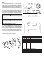
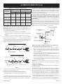
INTRODUCTION (CONT'D)
MODEL RH-25 RH-35
Input BTU.HR (KW/H) 25,000 (7.3) 35,000 (10.3)
Height 26" (660mm) 26" (660mm)
Width 37" (940mm) 37" (940mm)
Depth including diverter 18 3/8" (467mm) 18 3/8" (467mm)
Gas Inlet Pipe 1/2" (13mm) 1/2" (13mm)
Size of ue collar 4" (102mm) 4" (102mm)
Floor to top of collar on vertical position of Draft Diverter 22 15/16" (583mm) 22 15/16" (583mm)
Floor to center of collar on horizontal position of Draft Diverter 18 3/16" (462mm) 18 3/16" (462mm)
ACCESSORIES
Blower Package DRB1 DRB1
Floor Pad DVP1 DVP1
Conversion Kit Propane to Natural 33728 33729
Conversion Kit Natural to Propane 33730 33731
SPECIFICATIONS
CONVERSION KITS
Part Number Description Used On
33728 Propane to Natural RH25-8LPG
33730 Natural to Propane RH25-8NAT
33729 Propane to Natural RH35-7LPG
33731 Natural to Propane RH35-7NAT
When an existing Category 1 heater is removed or replaced, the
original venting system may no longer be sized to properly vent the
attached appliances. Instructions shall also indicate effects of an
improperly sized venting system (formation of condensate, leakage,
spillage, etc.) and shall specify the following test procedure:
WARNING
CARBON MONOXIDE POISONING HAZARD
Failure to follow the steps outlined below for each
appliance connected to the venting system being placed
into operation could result in carbon monoxide poisoning
or death.
The following steps shall be followed for each appliance
connected to the venting system being placed into
operation, while all other appliances connected to the
venting system are not in operation:
1. Seal any unused openings in the venting system.
2. Inspect the venting system for proper size and
horizontal pitch, as required in the National Fuel Gas
Code, ANSI Z223.1/NFPA 54 or the Natural Gas and
Propane Installation Code, CSA B149.1 and these
instructions. Determine that there is no blockage or
restriction, leakage, corrosion and other deciencies
which could cause an unsafe condition.
3. As far as practical, close all building doors and
windows and all doors between the space in which
the appliance(s) connected to the venting system are
located and other spaces of the building.
4. Close replace dampers.
5. Turn on clothes dryers and any appliance not connected
to the venting system. Turn on any exhaust fans, such
as range hoods and bathroom exhausts, so they are
operating at maximum speed. Do operate a summer
exhaust fan.
6. Follow the lighting instructions. Place the appliance
being inspected into operation. Adjust the thermostat
so appliance is operating continuously.
7. Test for spillage from draft hood equipped appliances
at the draft hood relief opening after 5 minutes of main
burner operation. Use the ame of a match or candle.
8. If improper venting is observed during any of the
above tests, the venting system must be corrected in
accordance with National Fuel Gas Code, ANSI Z223.1/
NFPA 54 and/or Natural Gas and Propane Installation
Code, CSA B149.1.
9. After is has been determined that each appliance
connected
to the venting system properly vents when
tested as outlined above, return doors, windows,
exhaust fans, replace dampers and any other gas-red
burning appliance to their previous conditions of use.
38151-4-0320Page 6

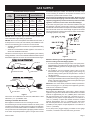
NOTICE: Never use plastic pipe. Check to conrm whether your
local codes allow copper tubing or galvanized.
NOTICE: Since some municipalities have additional local codes, it
is always best to consult your local authority and installation code.
The use of the following gas connectors is recommended:
— ANSI Z21.24 Appliance Connectors of Corrugated Metal Tubing
and Fittings
— ANSI Z21.45 Assembled Flexible Appliance Connectors of
Other Than All-Metal Construction
The above connectors may be used if acceptable by the authority
having jurisdiction. The Commonwealth of Massachusetts requires
that a exible appliance connector cannot exceed three feet in length.
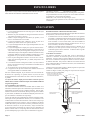
GAS SUPPLY
TEE HANDLE
FLEX TUBING
NPT NIPPLE
FLARE FITTING
FLARE SHUT OFF VA LVE
CLOSE NIPPLE
TEE HANDLE
NPT NIPPLE
NPT UNION
SHUT OFFVALVE
NPT GAS SUPPLY
Figure 1
Consult the current National Fuel Gas Code, ANSI Z223.1 CAN/
CGA-B149 (.1 or .2) installation code.
Installing a New Main Gas Shut-Off
Each appliance should have its own manual gas shut-off.
A manual main gas shut-off should be located in the vicinity of the
unit. Where none exists, or where its size or location is not adequate,
contact your local authorized installer for installation or relocation.
Compounds used on threaded joints of gas piping shall be resistant
to the action of liqueed petroleum gases. The gas lines must be
checked for leaks by the installer. This should be done with a soap
solution watching for bubbles on all exposed connections, and if
unexposed, a pressure test should be made.
Never use an exposed ame to check for leaks. Appliance must
be disconnected from piping at inlet of control valve and pipe
capped or plugged for pressure test. Never pressure test with
appliance connected; control valve will sustain damage!
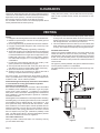
A gas valve and ground joint union should be installed in the gas
line upstream of the gas control to aid in servicing. It is required by
the National Fuel Gas Code that a drip line be installed near the gas
inlet. This should consist of a vertical length of pipe tee connected
into the gas line that is capped on the bottom in which condensation
and foreign particles may collect.
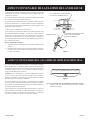
Figure 2
Method of Installing a Tee Fitting Sediment Trap
Pressure Testing of the Gas Supply System
1. To check the inlet pressure to the gas valve, a 1/8" (3mm) N.P.T.
plugged tapping, accessible for test gauge connection, must be
placed immediately upstream of the gas supply connection to
the appliance.
2. The appliance and its individual shutoff valve must be
disconnected from the gas supply piping system during any
pressure testing of that system at test pressures in excess of
1/2 psig (3.5 kPa).
3. The appliance must be isolated from the gas supply piping system
by closing its individual manual shutoff valve during any pressure
testing of the gas supply piping system at test pressures equal
to or less than 1/2 psig (3.5 kPa).
Attention! If one of the above procedures results in pressures in
excess of 1/2 psig (14" w.c.) (3.5 kPa) on the appliance gas valve,
it will result in a hazardous condition.
Checking Manifold Pressure
Both Propane and Natural Gas valves have a built-in pressure
regulator in the gas valve. Natural Gas models will have a manifold
pressure of approximately 4.0" w.c. (.996kPa) at the valve outlet
with the inlet pressure to the valve from a minimum of 5.0" w.c.
(1.245kPa) for the purpose of input adjustment to a maximum of
10.5" w.c. (2.61kPa). Propane Gas models will have a manifold
pressure approximately 10.0" w.c. (2.49kPa) at the valve outlet
with the inlet pressure to the valve from a minimum of 11.0" w.c.
(2.739kPa) for the purpose of input adjustment to a maximum of
13.0" w.c. (3.237kPa).
A 1/8" (3mm) N.P.T. plugged tapping, accessible for test gauge
connection, is located on the outlet side of the gas control.
Recommended Gas Pipe Diameter
Pipe
Length
Schedule 40 Pipe
Inside Diameter
Tubing, Type L
Outside Diameter
Natural Propane Natural Propane
0-10 feet
0-3 meters
1/2”
12.7mm
3/8”
9.5mm
1/2”
12.7mm
3/8”
9.5mm
10-40 feet
4-12 meters
1/2”
12.7mm
1/2”
12.7mm
5/8”
15.9mm
1/2”
12.7mm
40-100 feet
13-30 meters
1/2”
12.7mm
1/2”
12.7mm
3/4”
19mm
1/2”
12.7mm
100-150 feet
31-46 meters
3/4”
19mm
1/2”
12.7mm
7/8”
22.2mm
3/4”
19mm
GAS SUPPLY
38151-4-0320 Page 7

Clearances: When facing the front of the room heater the minimum
clearances to combustible construction (material) are the following:
Right side 6 inches (152mm). Left side 6 inches (152mm).
Recommend 18 inches (457mm) on left side for servicing.
Do not install in alcove or closet. No horizontal projection above
heater permitted within 48 inches (122cm).
Ceiling 48 inches (122cm). Rear of draft hood 2 inches (51mm).
Open in front to provide service, access, and clearance to com-
bustibles.
Venting
1. Flue pipe must be as large as the ue collar on the draft diverter.
2. Maintain an upward slope of at least 1/4 inch (6mm) per foot
(.3m) of horizontal run.
3. Run ue pipe as directly as possible with a minimum of elbows.
4. Flue pipe should extend through the wall of a chimney to be
ush with inner wall.
5. Flue pipe must be adequately supported by metal strips.
6. Single wall vent pipe may be attached directly to the draft hood
of the room heater when a clearance of 2 1/2 inches (64mm)
is maintained between the single wall vent pipe and the com-
bustible wall of the room in which the room heater is located.
Use double wall vent pipe for a 1 inch (25mm) clearance to
combustibles.
7. For ue pipe running through walls and roof, use B-1 [1 inch
(25mm) clearance to combustibles) vent pipe.
8. Chimneys should extend at least 2 feet (.6m) above the roof
and above any object or nearby building within 10 feet (3m).
9. Open tees should not be used in the ue pipe.
10. Appliance must not be connected to a chimney ue that is
servicing a separate solid-fuel burning appliance.
For proper venting, do not attach a 90° elbow directly to draft di-
verter. If possible, attach 2 feet (.6m) of straight vent pipe before
an elbow is used. Use 45° elbows if possible.
Uninsulated single-wall metal pipe shall not be used outdoors
in cold climates for venting gas utilization equipment.
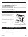
Ventilation and Combustion Air
Room heaters shall be installed in a location in which the facilities
for ventilation permit satisfactory combustion of gas and proper
venting under normal conditions. In buildings of conventional
frame, brick or stone construction without tight storm windows and
doors, inltration is normally adequate to provide for combustion
and draft hood dilution.
Where appliances are installed in a conned space within a building,
the building being of unusually tight construction, air for combustion
and ventilation must be obtained directly from outdoors or from
such spaces that freely communicate with the outdoors. Under
these conditions, the conned space shall be provided with two
permanent openings, one near the top of the enclosure and one
near the bottom; each opening shall have a free area of not less
than one square inch (6.5cm
2
)per 1,000 BTU’s (.3KW/H) of total
input. The draft hood must be in the same atmospheric pressure
zone as the combustion air inlet to the appliance.
Liner and Insulated Liner
When you install a vented room heater into a masonry chimney
you must follow these steps.
1. The chimney must be lined and sized properly. Most masonry
chimneys are over sized and absorb too much heat to be con-
sidered a proper vent. If you have any doubts line the chimney
with the right size liner. If it’s unlined you must line it.
2. Use an insulated liner when the chimney is on the outside, three
sides exposed to the weather, and there is no clay liner in the
chimney. The insulation will help keep the ue gases warmer.
Insulated Vent Enclosure
Vented room heaters installed with the vent going directly to the
outside and above the eaves can cause poor venting. The cold
pipe will have a delay in proper venting and cause the room heater
to shut “off” by the vent safety switch. To prevent delayed venting
as well as condensation of ue products an insulated enclosure is
recommended.
Use type B 4" (102mm) diameter vent pipe and maintain at least a
one inch (25mm) clearance to combustibles.
Use metal thimble to protect vent pipe as it passes through com-
bustibles.
Figure 3
VENTING
CLEARANCES
38151-4-0320Page 8

38151-4-0320 Page 9
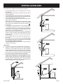
VENTING GUIDELINES
The installer must consider all of the following venting rules.
• Flue pipe MUST always have an upward slope (1/4 inch per
foot minimum).
• Flue pipe MUST run as directly as possible and have as few
elbows as possible.
• Flue pipe MUST be as large as the ue collar on the draft diverter.
• The ue pipe MUST be on the outside of the draft diverter collar.
• The ue pipe MUST be sealed. No open “Tees.”
• The ue pipe’s vertical rise MUST always be at least twice the
length of the horizontal run.
• Each new piece of ue pipe that is connected when getting
farther away from the furnace MUST connect on the outside
of the previous one. Remember, the exhaust must ow “into”
the next pipe.
• For ue pipe running through walls, roof and within one inch
of combustible construction, use B-1 (one inch clearance to
combustibles) vent pipe. Any combustible material that is within
2 inches of the vent connection or the draft diverter must be
shielded with a non-combustible material.
• When connecting the ue pipe to the chimney, the pipe MUST
go fully in and be cemented. The ue pipe MUST NOT go too
far into the chimney. It should be cut off as it will interfere with
normal venting.
• Flue pipe MUST NOT have any downward sloping sections,
dips or sags.
• Do not use Type C single wall ue pipe. Uninsulated single-
wall metal pipe shall not be used outdoors in cold climates
for venting gas utilization equipment.
• The ue pipe MUST NOT be connected to a chimney that has
a replace connected to it.
Helpful Hints
1. If you have a choice, select a location close to the chimney.
2. If there is no chimney, you will have to run a ue pipe from
the furnace, up to and above the house roof. Select a location
permitting the most direct run. Try going up to the roof through
a closet. Remember that the ue pipe must slope upwards at
least 1/4 of an inch for each foot and you may nd oor joists
in your path, so it is important to plan the run carefully.
3. If you have decided to go up to the roof through a closet, re-
member that you MUST keep a minimum distance of 1 inch
between Type B vent pipe and any combustible material. Run
it through a single wall pipe that is 2 inches larger in diameter
than the ue pipe. Use thimbles when going through oor and
ceiling and ashing when going through roof.
ROOF LINE
ROOF LINE
ROOF LINE
ROOF LINE

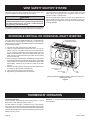
This heater must be properly connected to a venting system. This
heater is equipped with a vent safety shutoff system.
WARNING
Operation of this heater, when not connected to a properly
installed and maintained venting system or tampering with the
vent safety shutoff system, can result in carbon monoxide
(CO) poisoning and possible death.
This appliance needs fresh air for safe operation and must be installed
so there are provisions for adequate combustion and ventilation air.
This room heater is equipped with a vent safety switch. The vent
safety switch will cause gas ow to the pilot to “shut off” due to
improper venting or a blocked ue.
If the vent safety switch continues to “shut off” the gas ow to the
pilot a qualied service person must be contacted to inspect for
improper venting, blockage in the vent pipe or the vent safety switch
for being defective.
REVERSIBLE DRAFT
DIVERTER ASSEMBLY
VENT SAFETY
SWITCH
VENT SAFETY
WIRE
GAS
VALVE
DRAFT DIVERTER CAN BE EITHER A VERTICAL VENT OR
HORIZONTAL VENT
Figure 4
This room heater has a reversible draft diverter. The draft diverter
is installed in the vertical position at the factory. Please use the
following steps to change the draft diverter from the vertical position
to the horizontal position.
1. Remove vent safety switch from the draft diverter.
2. Inside your yellow instruction envelope will be a 1 1/2" x 2 1/4"
(38mm x 51mm) vent safety switch hole cover plate and two
(2) 1/2" screws for attachment of vent safety switch hole cover
plate to the draft diverter. Attach vent safety switch hole cover
plate over hole on the draft diverter from which the vent safety
switch was removed.
3. Remove two (2) screws at bottom of draft diverter and lift upward
to remove draft diverter from the draft diverter plate. Rotate draft
diverter into the horizontal position and slide back into the draft
diverter plate. Attach two (2) screws into bottom of the draft
diverter.
4. Remove vent safety switch hole knockout and two (2) knockouts
for screws on opposite side of draft diverter.
5. Attach vent safety switch to the draft diverter.
6. Repositioning of the draft diverter is completed.
Thermostat Operation
To turn on burner, rotate dial knob toward setting number 7. To shut
down burner, rotate dial knob toward number 1.
The dial numbers 1 through 7 correspond to 50° (10°C) through
90°F (32°C). This is the temperature at the bulb thermostat not the
room temperature. The owner is advised to determine the particular
heat setting that is desired for comfort, as heating requirements are
different for every owner.
Attention: If no heat is desired, turn the gas control knob to the
PILOT position.
THERMOSTAT OPERATION
REVERSIBLE VERTICAL OR HORIZONTAL DRAFT DIVERTER
VENT SAFETY SHUTOFF SYSTEM
38151-4-0320Page 10

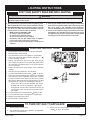
1. STOP! Read the safety information to the left of this label.
2. Set thermostat to lowest setting.
3. Turn off all electric power to the appliance. (If applicable)
4. Push in gas control knob slightly and turn clockwise
to “OFF”. DO NOT FORCE.
5. Wait ten (10) minutes to clear out any gas. Then smell for
gas, including near the oor. If you smell gas, STOP! Follow
“B” in the safety information above. If you do not smell gas,
go to the next step.
6. Remove the pilot access cover located on the combustion
chamber.
7. Find pilot -the pilot is attached to front of burner.
8. Turn gas control knob counterclockwise
to “PILOT”.
9. Push in gas control knob all the way and hold in. Immediately
press the Piezo Ignitor repeatedly until the pilot is ignited.
Continue to hold the control knob in for about one (1) minute
after pilot is lit. Release knob and it will pop back up. The Pilot
should remain lit. If it goes out, repeat steps 4 through 9.
• If knob does not pop up when released, stop and im-
mediately call your service technician or gas supplier.
• If the pilot will not stay lit after several tries, turn the gas
control knob to “OFF” and call your service technician or
gas supplier.
10. Turn gas control knob counterclockwise
to “ON”.
11. Turn on all electric power to the appliance. (If applicable)
12. Replace access panel (front panel).
13. Set thermostat to desired setting.
TO TURN OFF GAS TO APPLIANCE
A. This appliance has a pilot which must be lighted by hand.
When lighting the pilot, follow these instructions exactly.
B. BEFORE LIGHTING smell all around the appliance area for
gas. Be sure to smell next to the oor because some gas
is heavier than air and will settle on the oor.
WHAT TO DO IF YOU SMELL GAS
• Do not try to light any appliance.
• Do not touch any electrical switch;
do not use any phone in your building.
• Immediately call your gas supplier from a neighbor's
phone. Follow the gas supplier's instructions.
• If you cannot reach your gas supplier, call the re de-
partment.
C. Use only your hand to push in or turn the gas control knob.
Never use tools. If the knob will not push in or turn by hand,
don't try to repair it; call a qualied service technician.
Force or attempted repair may result in a re or explosion.
D. Do not use this appliance if any part has been under water.
Immediately call a qualied service technician to inspect
the appliance and to replace any part of the control system
and any gas control which has been under water.
LIGHTING INSTRUCTIONS
1. Set thermostat to lowest setting.
2. Turn off all electric power to the appliance. (If applicable)
If service is to be performed.
3. Push in gas control knob slightly and turn clockwise
to “OFF". Do not force.
FOR YOUR SAFETY READ BEFORE LIGHTING
WARNING
If you do not follow these instructions exactly, a re or explosion may result causing property damage,
personal injury or loss of life.
LIGHTING INSTRUCTIONS
38151-4-0320 Page 11

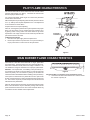
The correct ame will be almost horizontal, blue and will extend
past the thermocouple 1/4" (6mm). The ame will surround the
thermocouple just below the tip.
On Propane Gas slight yellow might occur where the pilot ame
and the burner ame meet.
Natural Gas pilots require adjusting when the inlet pressure is above
5" w.c. (1.25kPa) Remove pilot adjustment cover. Turn adjustment
screw clockwise to reduce ame.
Propane Gas will not require adjusting.
After use, cleaning of the pilot burner may be required for the proper
ame. The pilot orice can be cleaned with high pressure air or
by placing under running water. Pilot orice must be dry before
replacement. Use a pipe cleaner to clean inside the pilot after the
pilot orice has been removed.
To Remove Pilot Orice
1. Disconnect the pilot supply line at the pilot burner.
2. Remove pilot orice from pilot burner. It may be necessary to
tap on pilot burner in order to remove the pilot orice.
Figure 5
There will be a short blue inner ame with a larger, lighter blue
secondary ame. The burner ame may have yellow tips when hot.
Dust in the combustion air will produce an orange or red ame. Do
not mistake the orange or red ame for an improper yellow ame.
Attention: On Propane Gas, if a whistling noise (resonation) oc-
curs close the air shutter on the main burner in order to reduce the
amount of primary air. The reduction in primary air will soften the
main burner ame and will eliminate the whistling noise (resonation).
On Propane or Natural Gas if a yellow ame occurs open the air
shutter on the main burner in order to increase the amount of primary
air. The increase in primary air will sharpen the main burner and
will eliminate the yellow ame.
After use, cleaning of the main burner may be required for the proper
ame. The main burner may be cleaned by forcing water into the
ports and the throat of the burner. The burner should be blown dry
or heated to remove all water before replacement.
Figure 6
On Propane Gas, if a whistling noise (resonation) occurs
a. Close the air shutter on the main burner in order to reduce
the amount of primary air.
MAIN BURNER FLAME CHARACTERISTICS
PILOT FLAME CHARACTERISTICS
38151-4-0320Page 12

To Remove Main Burner
1. Disconnect the thermocouple and pilot supply line at the pilot
burner.
2. Unscrew the nut on the orice tting union. Orice tting is
threaded into the main burner.
3. Remove screw on each side of the main burner and lift out.
To Remove Main Burner Orice
1. Unscrew the nut on the orice tting union. Orice tting is
threaded into the main burner.
2. Unthread the orice tting from the main burner.
3. Main burner orice is located at the end of the orice tting.
4. Remove main burner orice from orice tting with a 1/2"
(13mm) wrench.
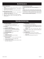
Cleaning Combustion Chamber
A qualied serviceman should remove the chamber and apply air
pressure to the inside in order to clear all passageways.
Oiling
The blower motor has an oil hole located on each end of the motor.
Use #20 motor oil only. It is best to oil the motor several times during
the heating season using 2 or 3 drops each time. If the motor fails
to start and hums, it could be a tight bearing due to lack of oil. This
may be corrected by pouring Kerosene in the oil holes, allowing to
stand for a few hours and then oiling properly.
1. Impossible to light pilot
a. If using Piezo ignitor, check electrode location.
b. Remove nut at orice and check for gas.
c. If gas available, check for blocked orice or pilot.
2. Pilot outage
a. Proper size of pilot ame.
b. Defective or weak thermocouple.
3. Pilot ames but goes out when knob is released
a. Pilot ame not covering the thermocouple properly.
b. Defective thermocouple.
c. Defective magnet in the safety section of valve.
4. Poor thermostat control
a. Defective thermostat section.
5. Noisy blower
a. Tighten blower screws.
b. Check blower wheel in the open for balance.
6. Yellow main burner ame
a. Remove main burner to check for obstructions in throat,
ports and orices.
b. Install new main burner orice and pilot orice.
c. Check gas valve for leaking.
d. Open the air shutter on the main burner in order to increase
the amount of primary air.
7. Yellow pilot ame
a. Small yellow tip not objectionable.
b. Remove pilot orice. Check and clean.
8. Pilot and main burner goes out after burning a few minutes
a. Improper venting of ue products. Relight and check for
improper venting.
b. If vented properly, check vent safety switch, replace if
defective.
9. Burner ashes- back or “pops” and burns at main burner
orice
a. Examine main burner for defects.
10. Inoperative blower
a. Check fan control by shorting across terminals.
b. Check for blower wheel bind by removing wheel and op-
erating motor.
c. Check for frozen bearings due to lack of oil.
TROUBLESHOOTING
MAINTENANCE
38151-4-0320 Page 13

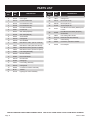
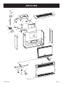
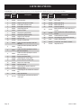
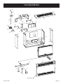
USE ONLY MANUFACTURER’S REPLACEMENT PARTS. USE OF ANY OTHER PARTS COULD CAUSE INJURY OR DEATH.
PARTS LIST
INDEX
NO.
PART
NO.
DESCRIPTION
1 R367 Knob
2 R9760 Piezo Ignitor
3 RH702 Control Rod Bracket
4 R3176 ECO Switch RH-25-8
4 R2706 ECO Switch RH-35-7
5 R8195 ECO Wire Assembly
6 29301 Control Rod
7 R2701 Gas Valve (Propane)
7 R2700 Gas Valve (Natural)
8 RH811 Valve Bracket
9 RH705 Casing Side
10 RH708 Air Inlet Bafe
11 P8635 Main Burner Orice, (RH-35-7 Natural)
11 P8643 Main Burner Orice,(RH-25-8 Natural)
11 P8651
Main Burner Orice, (RH-35-7 Propane)
11 P8654
Main Burner Orice, (RH-25-8 Propane)
12 29089 Inlet Tubing Assembly
13 RH818 Diverter Assembly
14 RH801 Down Draft Shield
15 RH799 Diverter Plate
16 DV951 Casing Top
17 32252 Inner Casing Assembly
18 RH705 Casing Side
19 RH691 Combustion Chamber Assembly
20 M155 Gasket
21 DV781 Lighting Hole Cover Assembly
INDEX
NO.
PART
NO.
DESCRIPTION
22 DV064 Cover Plate
23 15671 Casing Front
24 RH737 Burner (RH-25-8)
24 RH738 Burner (RH-35-7)
25 R1195 Thermocouple 36”
26 R1227
Pilot Burner with Orice (Natural) and
Ferrule
26 R1228
Pilot Burner with Orice (Propane)
and Ferrule
27 39254 Pilot Tubing with Ferrules
28 R11773 Electrode and Wire Assembly
29 P104 Orice Fitting
30 R2423 Connector, 5/16 tube x 3/8 NPT
31 R1630 ECO Adaptor
38151-4-0320Page 14

6
5
30
12
4
3
1
30
29
11
13
14
15
16
10
9
18
17
19
20
21
22
23
24
25
26
28
27
INSULATION
2
31
7
8
PARTS VIEW
38151-4-0320 Page 15

INSTRUCTIONS MUST BE LEFT WITH THE OWNER FOR FUTURE REFERENCE AFTER INSTALLATION
Installing Optional DRB-1 Blower
1. For RH-25 and RH-35, remove casing front.
1.
For DV-25-SG and DV-35-SG, remove casing front and heat shield.
2. When facing appliance, insert blower assembly into the left
section of the casing (adjacent to the combustion chamber).
3. For RH-25 and RH-35, route cord set through opening in casing
back. The opening in casing back is located adjacent to gas
control.
3. For DV-25-SG and DV-35-SG, route cord set through opening in
casing bottom. The opening in casing bottom is located beneath
gas control.
4. Align the (2) screw holes on the inner side panel and the (2)
screw holes on casing back with the (4) clearance holes on the
blower assembly. Attach blower assembly to the casing back
and inner side panel with (4) #10 x 1/2" (13mm) (13mm)screws
provided. The blower assembly must be attached rst to the
casing back and then to the casing side panel.
5. For RH-25 and RH-35, replace casing front.
6.
For DV-25-SG and DV-35-SG, replace heat shield and casing front.
Attention: Wiring harness on blower is factory assembled and
installed. If wiring harness becomes disassembled use the following
steps to reassemble the wiring harness.
1. Attach (1) pin terminal from black (hot) wire, smooth insulation
on cord set to (1) socket terminal on fan control assembly.
2. Attach (1) pin terminal from black (neutral) wire, ribbed insulation
on cord set to (1) socket terminal from white (neutral) wire on
motor.
3. Attach (1) pin terminal on fan control assembly to (1) socket
terminal from black (hot) wire on motor.
4. Attach green ground wire beneath one of the #10 x 1/2" (13mm)
screws on the blower housing.
Fan Control
The automatic fan control is located in the switch box. The switch
box is attached to the front of the blower assembly. The switch
box is adjacent to the combustion chamber. The fan control is a
non-adjustable automatic type. The fan control will require between
5 and 10 minutes of main burner operation before the fan control
"closes" and activates the blower. The blower will continue to run
between 5 and 10 minutes after the main burner shuts off, before
the fan control "opens" and deactivates the blower.
OPTIONAL BLOWER
INSTALLATION
INSTRUCTIONS
OPTIONAL BLOWER DRB-1
Vented Room Heaters
RH-25 and RH-35
Direct Vent Wall Furnaces
DV-25-SG, DV-35-SG
38151-4-0320Page 16

Wiring
The appliance, when installed, must be electrically grounded in
accordance with local codes or, in the absence of local codes, with
the National Electrical Code, ANSI/NFPA 70 or Canadian Electrical
Code, CSA C22.1, if an external electrical source is utilized. This
appliance is equipped with a three-prong [grounding] plug for your
protection against shock hazard and should be plugged directly into
a properly grounded three-prong receptacle. Do not cut or remove
the grounding prong from this plug. For an ungrounded receptacle,
an adapter, which has two prongs and a wire for grounding, can
be purchased, plugged into the ungrounded receptacle and its
wire connected to the receptacle mounting screws. With this wire
completing the ground, the appliance cord plug can be plugged into
the adapter and be electrically grounded.
CAUTION
Label all wires prior to disconnection when servicing controls.
Wiring errors can cause improper and dangerous operation.
Verify proper operation after servicing.
WARNING
Unplugging of blower accessory will not stop the heater
from cycling. To shut heater off: Turn temperature dial or
thermostat to lowest setting. Turn knob on gas control to
"OFF", depressing slightly. Do not force.
Cleaning
The blower wheel will collect lint and could require cleaning once
a year. If the air output decreases or the noise level increases, it
indicates a dirty wheel. Complete removal of the wheel and scrubbing
it with a brush under owing water is recommended.
Oiling
The blower motor has an oil hole located on each end of the motor.
Use #20 motor oil only. It is best to oil the motor several times during
the heating season using 2 or 3 drops each time. If the motor fails
to start and hums, it could be a tight bearing due to lack of oil. This
may be corrected by pouring Kerosene in the oil holes, allowing to
stand for a few hours and then oiling properly.
1
2
3
4
5
6
7
8
9
10
11
12
WHITE
MOTOR
BLACK
BLACK
BLACK
FAN CONTROL
SWITCH
BLACK RIBBED
BLACK SMOOTH
GREEN GROUND WIRE
NEUTRAL
SPT-2 CORD
HOT
PARTS LIST
INDEX
NO.
PART
NO.
DESCRIPTION
1 R-2090 Motor
2 R587 Motor Cushion
3 RH-036 Motor Support
4 R469 Blower Wheel
5 RH-710 Blower Housing Assembly
6 R1156 Fan Control Switch
7 R896 Heyco Bushing
8 DV-806 Switch Box
9 DV-807 Switch Box Cover
10 R-2091 Wire Assembly 19" (483mm)
11 R1468 Heyco Bushing
12 R-2099 Cord Set 72" (1.83m)
38151-4-0320 Page 17

To Order Parts Under Warranty, please contact your local Empire dealer. See the dealer locator at www.empirecomfort.
com. To provide warranty service, your dealer will need your name and address, purchase date and serial number, and the
nature of the problem with the unit.
To Order Parts After the Warranty Period, please contact your dealer or one of the Master Parts Distributors listed below.
This list changes from time to time. For the current list, please click on the Master Parts button at www.empirecomfort.com.
Please note: Master Parts Distributors are independent businesses that stock the most commonly ordered Original Equip-
ment repair parts for Heaters, Grills, and Fireplaces manufactured by Empire Comfort Systems Inc.
MASTER PARTS DISTRIBUTOR LIST
Parts Not Under Warranty
Parts can be ordered through your Service Person, Dealer, or a Master Parts Distributor. See this page for the Master Parts Distribu-
tors list. For best results, the service person or dealer should order parts through the distributor. Parts can be shipped directly to the
service person/dealer.
Warranty Parts
Warranty parts will need a proof of purchase and can be ordered by your Service Person or Dealer. Proof of purchase is required for
warranty parts.
All parts listed in the Parts List have a Part Number. When ordering parts, rst obtain the Model Number and Serial Number from the
name plate on your equipment. Then determine the Part Number (not the Index Number) and the Description of each part from the fol-
lowing illustration and part list. Be sure to give all this information . . .
Appliance Model Number Part Description
Appliance Serial Number Part Number
Type of Gas (Propane or Natural)
Do not order bolts, screws, washers or nuts. They are standard hardware items and can be purchased at any local hardware store.
Shipments contingent upon strikes, res and all causes beyond our control.
HOW TO ORDER REPAIR PARTS
Dey Distributing
1401 Willow Lake Boulevard
Vadnais Heights, MN 55101
Phone: 651-490-9191
Toll Free: 800-397-1339
Website: www.deydistributing.com
Parts: Heater, Hearth and Grills
F. W. Webb Company
200 Locust Street
Hartford, CT 06114
Phone: 860-722-2433
Toll Free: 800-243-9360
Fax: 860-293-0479
Toll Free Fax: 800-274-2004
Websites: www.fwwebb.com & www.victormfg.com
Parts: Heater, Hearth and Grills
East Coast Energy Products
10 East Route 36
West Long Branch, NJ 07764
Phone: 732-870-8809
Toll Free: 800-755-8809
Fax: 732-870-8811
Website: www.eastcoastenergy.com
Parts: Heater, Hearth and Grills
38151-4-0320Page 18

WARRANTY
Empire Comfort Systems Inc. warranties this space heating product to be free from defects at the time of purchase and for the periods
specied below. Space heating products must be installed by a qualied technician and must be maintained and operated safely, in
accordance with the instructions in the owner’s manual. This warranty applies to the original purchaser only and is not transferable.
All warranty repairs must be accomplished by a qualied gas appliance technician.
Limited Ten-Year Parts Warranty – Combustion Chamber
Empire promises to the owner that if the combustion chamber (see parts list) fails because of defective workmanship or
material with ten years from the date of purchase, Empire will repair or replace at Empire’s option.
Limited One-Year Parts Warranty – Remote Controls, Thermostats, Accessories, and Parts
Should any remote control, thermostat, accessory, or other part fail because of defective workmanship within one year from
the date of purchase, Empire will repair or replace at Empire’s option.
Duties Of The Owner
The appliance must be installed by a qualied installer and operated in accordance with the instructions furnished with the
appliance. A bill of sale, cancelled check, or payment record should be kept to verify purchase date and establish warranty
period. Ready access to the appliance for service.
What Is Not Covered
Damages that might result from the use, misuse, or improper installation of this appliance.
Travel, diagnostic costs and freight charges on warranted parts to and from the factory.
Claims that do not involve defective workmanship or materials.
Unauthorized service or parts replacements.
Removal and reinstallation cost.
Inoperable due to improper or lack of maintenance.
How To Get Service
To make a claim under this warranty, please have your receipt available and contact your installing dealer. Provide the dealer
with the model number, serial number, type of gas, and purchase verication. The installing dealer is responsible for providing
service and will contact the factory to initiate any warranted parts replacements. Empire will make replacement parts available
at the factory. Shipping expenses are not covered.
If, after contacting your Empire dealer, service received has not been satisfactory, contact: Consumer Relations Department,
Empire Comfort Systems Inc., PO Box 529, Belleville, Illinois 62222, or send an e-mail to [email protected] with
“Consumer Relations” in the subject line.
Your Rights Under State Law
This warranty gives your specic legal rights, and you may also have other rights, which vary from state to state.
38151-4-0320 Page 19

www.empirecomfort.com
Empire Comfort Systems Inc.
Belleville, IL
If you have a general question
about our products, please e-mail
us at [email protected].
If you have a service or repair
question, please contact your dealer.
38151-4-0320
La page est en cours de chargement...
La page est en cours de chargement...
La page est en cours de chargement...
La page est en cours de chargement...
La page est en cours de chargement...
La page est en cours de chargement...
La page est en cours de chargement...
La page est en cours de chargement...
La page est en cours de chargement...
La page est en cours de chargement...
La page est en cours de chargement...
La page est en cours de chargement...
La page est en cours de chargement...
La page est en cours de chargement...
La page est en cours de chargement...
La page est en cours de chargement...
La page est en cours de chargement...
La page est en cours de chargement...
La page est en cours de chargement...
La page est en cours de chargement...
-
 1
1
-
 2
2
-
 3
3
-
 4
4
-
 5
5
-
 6
6
-
 7
7
-
 8
8
-
 9
9
-
 10
10
-
 11
11
-
 12
12
-
 13
13
-
 14
14
-
 15
15
-
 16
16
-
 17
17
-
 18
18
-
 19
19
-
 20
20
-
 21
21
-
 22
22
-
 23
23
-
 24
24
-
 25
25
-
 26
26
-
 27
27
-
 28
28
-
 29
29
-
 30
30
-
 31
31
-
 32
32
-
 33
33
-
 34
34
-
 35
35
-
 36
36
-
 37
37
-
 38
38
-
 39
39
-
 40
40


Empire Console Vented Room Heaters (RH25/35) Le manuel du propriétaire
- Catégorie
- Cheminées
- Taper
- Le manuel du propriétaire
- Ce manuel convient également à
dans d''autres langues
Documents connexes
-
Empire Heating Systems RH-25-7 Le manuel du propriétaire
-
-
-
-
-
Empire GWT-50-3 SG Installation Instructions And Owner's Manual
-
-
-