Weber E210 Manuel utilisateur
- Catégorie
- Barbecues
- Taper
- Manuel utilisateur
Ce manuel convient également à

NATURAL GAS GRILL OWNER’S GUIDE
Thank you for purchasing a Weber
®
grill.
You’ve made a wise investment.
Now take a few minutes and protect it by
registering your product online at
www.weber.com.
®
GUÍA DEL PROPIETARIO DE LA BARBACOA DE GAS NATURAL - PG. 29
MODE D’EMPLOI DU GRILL À GAZ NATUREL - PG. 51
57206
US - ENGLISH
07/13/12
E210 · E310 · SP310
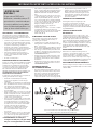
YOU MUST READ THIS OWNER’S GUIDE BEFORE
OPERATING YOUR GAS GRILL.
m DANGER
If you smell gas:
1) Shut off gas to the appliance.
2) Extinguish any open ames.
3) Open lid.
4) If odor continues, keep away from the appliance and
immediately call your gas supplier or your re department.
Leaking gas may cause a re or explosion which can cause
serious bodily injury, death, or damage to property.
m WARNING
1) Do not store or use gasoline or other ammable liquids or
vapors in the vicinity of this or any other appliance.
2) An LP cylinder not connected for use shall not be stored
in the vicinity of this or any other appliance.
m WARNING: Carefully follow
all leak-check procedures
in this Owner’s Guide prior
to grill operation. Do this
even if the grill was dealer-
assembled.
m WARNING: Do not ignite
this appliance without
rst reading the BURNER
IGNITION sections of this
Owner’s Guide.
THIS GAS APPLIANCE IS
DESIGNED FOR OUTDOOR
USE ONLY.
NOTICE TO INSTALLER:
These instructions must be left
with the owner, who should
keep them for future use.

2 WWW.WEBER.COM
®
WARNINGS
m DANGER
Failure to follow the DANGERS,
WARNINGS and CAUTIONS contained in
this Owner’s Guide may result in serious
bodily injury or death, or may result in a
re or an explosion causing damage to
property.
WARNINGS:
m Improper assembly of grill may be
dangerous. Please follow the assembly
instructions carefully.
m Do not use this grill unless all parts
are in place. The grill must be properly
assembled according to the assembly
instructions.
m Your Weber
®
gas grill should never be
used by children. Accessible parts of
the grill may be very hot. Keep young
children away while grill is in use.
m Exercise caution when using your
Weber
®
gas grill. It will be hot during
cooking or cleaning, and should never
be left unattended, or moved while in
operation.
m Do not use charcoal or lava rock in
your Weber
®
gas grill.
m While igniting the grill or cooking,
never lean over open grill.
m Never place hands or ngers on the
front edge of the cookbox when the
grill is hot or the lid is open.
m Do not attempt to disconnect any gas
tting while your grill is in operation.
m Use heat-resistant barbecue mitts or
gloves when operating grill.
m Keep the cooking area clear of
ammable vapors and liquids such
as gasoline, alcohol, etc., and
combustible materials.
m Should the burners go out while grill
is in operation, turn all gas valves off.
Open the lid and wait ve minutes
before attempting to relight grill, using
the igniting instructions.
m Do not use the grill within 24 inches of
combustible materials. This includes
the top, bottom, back or sides of the
grill.
m Do not build this model of grill in
any built-in or slide-in construction.
Ignoring this WARNING could cause a
re or an explosion that can damage
property and cause serious bodily
injury or death.
m Only use this grill outdoors in a well-
ventilated area. Do not use in a garage,
building, breezeway or any other
enclosed area.
m Your Weber
®
gas grill shall not be
used beneath overhead combustible
construction.
m Your Weber
®
gas grill is not intended
to be installed in or on recreational
vehicles and/or boats.
m Do not store an extra (spare) or
disconnected liquid propane cylinder
under or near this grill.
m After a period of storage and/
or nonuse, the Weber
®
gas grill
should be checked for gas leaks and
burner obstructions before use. See
instructions in this Owner’s Guide for
correct procedures.
m Do not operate the Weber
®
gas grill if
there is a gas leak present.
m Do not use a ame to check for gas
leaks.
m Do not put a grill cover or anything
ammable on, or in the storage
area under, the grill while grill is in
operation or is hot.
m Natural gas is not liquid propane gas.
The conversion or attempted use of
liquid propane gas in a natural gas unit
or natural gas in a liquid propane gas
unit is dangerous and will void your
warranty.
m Keep any electrical supply cord and
the fuel supply hose away from any
heated surfaces.
m Do not enlarge valve orices or burner
ports when cleaning the valves or
burners.
m The Weber
®
gas grill should be
thoroughly cleaned on a regular basis.
m Should a grease re occur, turn off all
burners and leave lid closed until re
is out.
ADDITIONAL WARNINGS
FOR STATE OF CALIFORNIA:
m Combustion byproducts produced
when using this product contain
chemicals known to the state of
California to cause cancer, birth
defects, or other reproductive harm.
m Proposition 65 Warning: Handling the
brass material on this product exposes
you to lead, a chemical known to the
state of California to cause cancer,
birth defects or other reproductive
harm. (Wash hands after handling this
product.)

WWW.WEBER.COM
®
3
WARRANTY TABLE OF CONTENTS
Weber-Stephen Products LLC (Weber) hereby warrants to the
ORIGINAL PURCHASER of this Weber
®
gas grill that it will be free
of defects in material and workmanship from the date of purchase
as follows:
Aluminum castings: 25 years
(2 years on paint; excludes fading)
Stainless steel shroud: 25 years
Porcelain-enameled shroud: 25 years
Stainless steel burner tubes: 10 years
Stainless steel cooking grates: 5 years no rust through or burn through
Stainless steel Flavorizer
®
bars: 5 years no rust through or burn through
Porcelain-enameled
cast-iron cooking grates: 5 years no rust through or burn through
Porcelain-enameled cooking grates: 3 years no rust through or burn through
Porcelain-enameled Flavorizer
®
bars: 2 years no rust through or burn through
Infrared rotisserie burner: 2 years
All remaining parts: 2 years
when assembled and operated in accordance with the printed
instructions accompanying it. Weber may require reasonable proof
of your date of purchase. THEREFORE, YOU SHOULD RETAIN
YOUR SALES SLIP OR INVOICE.
This Limited Warranty shall be limited to the repair or replacement
of parts that prove defective under normal use and service and
which on examination shall indicate, to Weber’s satisfaction, they
are defective. Before returning any parts, contact the Customer
Service Representative in your area using the contact information
on our website. If Weber conrms the defect and approves the
claim, Weber will elect to replace such parts without charge. If you
are required to return defective parts, transportation charges must
be prepaid. Weber will return parts to the purchaser, freight or
postage prepaid.
This Limited Warranty does not cover any failures or operating
difficulties due to accident, abuse, misuse, alteration,
misapplication, vandalism, improper installation or improper
maintenance or service, or failure to perform normal and routine
maintenance, including but not limited to damage caused by insects
within the burner tubes, as set out in this Owner’s Guide.
Deterioration or damage due to severe weather conditions such
as hail, hurricanes, earthquakes or tornadoes, discoloration due to
exposure to chemicals either directly or in the atmosphere, is not
covered by this Limited Warranty.
There are no other express warrants except as set forth herein and
any applicable implied warranties of merchantability and tness are
limited in duration to the period of coverage of this express written
Limited Warranty. Some regions do not allow limitation on how long
an implied warranty lasts, so this limitation may not apply to you.
Weber is not liable for any special, indirect or consequential
damages. Some regions do not allow the exclusion or limitation of
incidental or consequential damages, so this limitation or exclusion
may not apply to you.
Weber does not authorize any person or company to assume
for it any other obligation or liability in connection with the sale,
installation, use, removal, return, or replacement of its equipment;
and no such representations are binding on Weber.
This Warranty applies only to products sold at retail.
WEBER-STEPHEN PRODUCTS LLC
Customer Service Center
90 West Hillcrest Boulevard, Suite 308
Schaumburg, IL 60195
USA
For replacement parts, call:
1-800-446-1071
Visit www.weber.com
®
, select your country of origin, and
register your grill today.
The grills illustrated in this Owner's Guide may have slight
differences than the model purchased.
WARNINGS ............................................................ 2
WARRANTY ........................................................... 3
TABLE OF CONTENTS ................................................... 3
SPIRIT
®
E210 NG EXPLODED VIEW ........................................ 4
SPIRIT
®
E310 NG EXPLODED VIEW ........................................ 6
SPIRIT
®
SP310 NG EXPLODED VIEW ....................................... 8
IMPORTANT INFORMATION ABOUT NATURAL GAS ......................... 10
WHAT IS NATURAL GAS? ..................................................................................10
NATURAL GAS — THE BASICS .............................................................................10
PIPING SPECIFICATIONS ..................................................................................10
STORAGE AND/OR NONUSE ...............................................................................10
PRESSURE TESTING GAS SUPPLY .........................................................................10
CONNECTION TESTING ...................................................................................10
US INSTALLATION CODES .................................................................................10
CANADIAN INSTALLATION .................................................................................10
CONNECTING TO THE GAS SUPPLY ...................................... 11
ALMOST READY TO GRILL .................................................................................11
CONNECTING THE FLEXIBLE HOSE TO GAS SUPPLY ..........................................................11
PREPARING TO USE YOUR GRILL ........................................12
WHAT IS A LEAK CHECK? .................................................................................12
PARTIAL DISASSEMBLY OF YOUR GRILL FOR A LEAK CHECK ...................................................12
CHECKING FOR GAS LEAKS ...............................................................................13
GRILLING TIPS & HELPFUL HINTS ....................................... 14
TIPS & HINTS ............................................................................................14
PREHEATING ............................................................................................14
COVERED COOKING .....................................................................................14
FLAVORIZER
®
SYSTEM ....................................................................................14
DRIPPINGS AND GREASE .................................................................................14
SAFETY CHECKS BEFORE USING YOUR GRILL .............................15
SAFETY FIRST ...........................................................................................15
SLIDE-OUT GREASE TRAY .................................................................................15
CATCH PAN AND DISPOSABLE DRIP PAN ....................................................................15
HOSE INSPECTION .......................................................................................15
MAIN BURNER IGNITION & USAGE .......................................16
METHODS OF BURNER IGNITION ...........................................................................16
MAIN BURNER IGNITION ..................................................................................16
TO EXTINGUISH BURNER .................................................................................16
TROUBLESHOOTING ................................................... 18
GENERAL TROUBLESHOOTING ............................................................................18
ANNUAL MAINTENANCE ...............................................19
KEEPING YOUR WEBER
®
GAS GRILL IN TIP-TOP SHAPE ........................................................19
BURNER FLAME PATTERN .................................................................................19
WEBER
®
SPIDER/INSECT SCREENS ........................................................................19
BURNER TUBE PORTS ....................................................................................19
BURNER TUBE CLEANING OR REPLACEMENT. . . . . . . . . . . . . . . . . . . . . . . . . . . . . . . . . . . . . . . . . . . . . . . . . . . . . . . . . . . . . . . .20
STORAGE AND/OR NONUSE ...............................................................................24
ROUTINE MAINTENANCE ...............................................25
BEAUTIFUL—INSIDE AND OUT .............................................................................25
CLEANING THE OUTSIDE OF THE GRILL .....................................................................25
CLEANING THE INSIDE OF THE GRILL .......................................................................25
HOSE INSPECTION .......................................................................................25
MAINTAINING THE ELECTRONIC CROSSOVER
®
IGNITION SYSTEM ...............................................26
MEMO ...............................................................27

4 WWW.WEBER.COM
®
SPIRIT
®
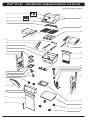
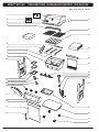
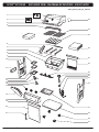
E210 NG EXPLODED VIEW · DIAGRAMA DE DESPIECE · VUE ECLATEE
Spirit_E210_NG_US_042512
1
2
3
4
5
6
7
8
9
10
11
12
13
14
15
16
17
18
19
20
21
22
23
24
26
25
27
28
29
30
31
32
33
34
35
36

WWW.WEBER.COM
®
5
SPIRIT
®
E210 NG EXPLODED VIEW · DIAGRAMA DE DESPIECE · VUE ECLATEE
SPIRIT
®
E210 NG
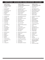
EXPLODED VIEW LIST
1. Thermometer and Bezel
2. Logo Plate
3. Shroud Assembly
4. Warming Rack
5. Crossover
®
Burner Tube
6. Igniter Electrode
7. Burner Tube
8. Cookbox
9. Disposable Drip Pan
10. Left Frame Panel
11. Catch Pan
12. Catch Pan Holder
13. Matchstick Holder
14. Igniter Module
15. Control Knob
16. Igniter Button
17. Control Panel
18. Front Cross Brace
19. Door
20. Door Handle
21. Shroud Hardware
22. Cooking Grate
23. Flavorizer
®
Bar
24. Fold-Down Side Table
25. Fold-Down Assembly
26. Rear Cross Brace
27. Rear Panel
28. Manifold
29. Manifold Hose
30. Bulkhead
31. NG Hose
32. Right Frame Panel
33. Slide-Out Grease Tray
34. Bottom Panel
35. Caster
36. Locking Caster
SPIRIT
®
E210 NG
LISTA DEL DIAGRAMA DE DESPIECE
1. Termómetro y bisel
2. Placa del logotipo
3. Ensamblaje de la cubierta
4. Rejilla para calentar
5. Tubo del quemador Crossover
®
6. Electrodo de encendido
7. Tubo del quemador
8. Caja de cocción
9. Bandeja de goteo desechable
10. Panel izquierdo del bastidor
11. Plato recolector
12. Soporte del plato recolector
13. Portacerillos
14. Módulo de encendido
15. Perilla de control
16. Botón de encendido
17. Tablero de control
18. Refuerzo transversal delantero
19. Puerta
20. Asa de la puerta
21. Accesorios de la cubierta
22. Parrilla de cocción
23. Barra Flavorizer
®
24. Mesa lateral
25. Ensamble plegable
26. Refuerzo transversal posterior
27. Panel posterior
28. Múltiple
29. Manguera del múltiple
30. Bloque de conexiones
31. Manguera del gas natural
32. Panel derecho del bastidor
33. Bandeja deslizante de grasa
34. Panel inferior
35. Rueda giratoria
36. Rueda giratoria con bloqueo
SPIRIT
®
E210 NG
LISTE DE LA VUE ÉCLATÉE
1. Thermomètre et bec
2. Plaque du logo
3. Assemblage du châssis
4. Grille de maintien au chaud
5. Tube du brûleur Crossover
®
6. Électrode de l’allumeur
7. Tube du brûleur
8. Boîtier de cuisson
9. Égouttoir jetable
10. Panneau du châssis gauche
11. Égouttoir
12. Support de l’égouttoir
13. Porte-allumette
14. Module de l’allumeur
15. Bouton de commande
16. Bouton de l’allumeur
17. Panneau de commande
18. Croisillon avant
19. Porte
20. Poignée de porte
21. Quincaillerie du châssis
22. Grille de cuisson
23. Barre Flavorizer
®
24. Tablette latérale
25. Assemblage pliable
26. Croisillon arrière
27. Panneau arrière
28. Collecteur
29. Tuyau du collecteur
30. Cloison
31. Tuyau GN
32. Panneau du châssis droit
33. Plateau de récupération
des graisses amovible
34. Panneau inférieur
35. Roulette
36. Roulette à verrouillage

6 WWW.WEBER.COM
®
SPIRIT
®
E310 NG EXPLODED VIEW · DIAGRAMA DE DESPIECE · VUE ECLATEE
Spirit_E310_NG_US_042512
1
2
3
4
5
6
7
8
9
10
11
12
13
14
15
16
17
18
19
20
21
22
23
24
25
26
27
28
29
30
31
32
33
34
35

WWW.WEBER.COM
®
7
SPIRIT
®
E310 NG EXPLODED VIEW · DIAGRAMA DE DESPIECE · VUE ECLATEE
SPIRIT
®
E310 NG
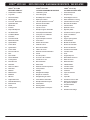
EXPLODED VIEW LIST
1. Thermometer and Bezel
2. Logo Plate
3. Shroud Assembly
4. Warming Rack
5. Crossover
®
Burner Tube
6. Igniter Electrode
7. Burner Tube
8. Cookbox
9. Disposable Drip Pan
10. Left Frame Panel
11. Catch Pan
12. Catch Pan Holder
13. Matchstick Holder
14. Igniter Module
15. Control Knob
16. Igniter Button
17. Control Panel
18. Front Cross Brace
19. Door
20. Door Handle
21. Shroud Hardware
22. Cooking Grate
23. Flavorizer
®
Bar
24. Side Table
25. Rear Cross Brace
26. Rear Panel
27. Manifold
28. Manifold Hose
29. Bulkhead
30. NG Hose
31. Right Frame Panel
32. Slide-Out Grease Tray
33. Bottom Panel
34. Caster
35. Locking Caster
SPIRIT
®
E310 NG
LISTA DEL DIAGRAMA DE DESPIECE
1. Termómetro y bisel
2. Placa del logotipo
3. Ensamblaje de la cubierta
4. Rejilla para calentar
5. Tubo del quemador Crossover
®
6. Electrodo de encendido
7. Tubo del quemador
8. Caja de cocción
9. Bandeja de goteo desechable
10. Panel izquierdo del bastidor
11. Plato recolector
12. Soporte del plato recolector
13. Portacerillos
14. Módulo de encendido
15. Perilla de control
16. Botón de encendido
17. Tablero de control
18. Refuerzo transversal delantero
19. Puerta
20. Asa de la puerta
21. Accesorios de la cubierta
22. Parrilla de cocción
23. Barra Flavorizer
®
24. Mesa lateral
25. Refuerzo transversal posterior
26. Panel posterior
27. Múltiple
28. Manguera del múltiple
29. Bloque de conexiones
30. Manguera del gas natural
31. Panel derecho del bastidor
32. Bandeja deslizante de grasa
33. Panel inferior
34. Rueda giratoria
35. Rueda giratoria con bloqueo
SPIRIT
®
E310 NG
LISTE DE LA VUE ÉCLATÉE
1. Thermomètre et bec
2. Plaque du logo
3. Assemblage du châssis
4. Grille de maintien au chaud
5. Tube du brûleur Crossover
®
6. Électrode de l’allumeur
7. Tube du brûleur
8. Boîtier de cuisson
9. Égouttoir jetable
10. Panneau du châssis gauche
11. Égouttoir
12. Support de l’égouttoir
13. Porte-allumette
14. Module de l’allumeur
15. Bouton de commande
16. Bouton de l’allumeur
17. Panneau de commande
18. Croisillon avant
19. Porte
20. Poignée de porte
21. Quincaillerie du châssis
22. Grille de cuisson
23. Barre Flavorizer
®
24. Tablette latérale
25. Croisillon arrière
26. Panneau arrière
27. Collecteur
28. Tuyau du collecteur
29. Cloison
30. Tuyau GN
31. Panneau du châssis droit
32. Plateau de récupération
des graisses amovible
33. Panneau inférieur
34. Roulette
35. Roulette à verrouillage

8 WWW.WEBER.COM
®
SPIRIT
®
SP310 NG EXPLODED VIEW · DIAGRAMA DE DESPIECE · VUE ECLATEE
Spirit_SP310_NG_US_042512
1
2
3
4
5
6
7
8
9
10
11
12
13
14
15
16
17
18
19
20
21
22
23
24
25
26
27
28
29
30
31
32
33
34
35
36

WWW.WEBER.COM
®
9
SPIRIT
®
SP310 NG EXPLODED VIEW · DIAGRAMA DE DESPIECE · VUE ECLATEE
SPIRIT
®
SP310 NG
EXPLODED VIEW LIST
1. Thermometer and Bezel
2. Logo Plate
3. Shroud Assembly
4. Warming Rack
5. Crossover
®
Burner Tube
6. Igniter Electrode
7. Burner Tube
8. Cookbox
9. Disposable Drip Pan
10. Left Frame Panel
11. Condiment Basket
12. Catch Pan
13. Catch Pan Holder
14. Matchstick Holder
15. Igniter Module
16. Control Knob
17. Igniter Button
18. Control Panel
19. Front Cross Brace
20. Door
21. Door Handle
22. Shroud Hardware
23. Cooking Grate
24. Flavorizer
®
Bar
25. Side Table
26. Rear Cross Brace
27. Rear Panel
28. Manifold
29. Manifold Hose
30. Bulkhead
31. NG Hose
32. Right Frame Panel
33. Slide-Out Grease Tray
34. Bottom Panel
35. Caster
36. Locking Caster
SPIRIT
®
SP310 NG
LISTA DEL DIAGRAMA DE DESPIECE
1. Termómetro y bisel
2. Placa del logotipo
3. Ensamblaje de la cubierta
4. Rejilla para calentar
5. Tubo del quemador Crossover
®
6. Electrodo de encendido
7. Tubo del quemador
8. Caja de cocción
9. Bandeja de goteo desechable
10. Panel izquierdo del bastidor
11. Cesta para los condimentos
12. Plato recolector
13. Soporte del plato recolector
14. Portacerillos
15. Módulo de encendido
16. Perilla de control
17. Botón de encendido
18. Tablero de control
19. Refuerzo transversal delantero
20. Puerta
21. Asa de la puerta
22. Accesorios de la cubierta
23. Parrilla de cocción
24. Barra Flavorizer
®
25. Mesa lateral
26. Refuerzo transversal posterior
27. Panel posterior
28. Múltiple
29. Manguera del múltiple
30. Bloque de conexiones
31. Manguera del gas natural
32. Panel derecho del bastidor
33. Bandeja deslizante de grasa
34. Panel inferior
35. Rueda giratoria
36. Rueda giratoria con bloqueo
SPIRIT
®
SP310 NG
LISTE DE LA VUE ÉCLATÉE
1. Thermomètre et bec
2. Plaque du logo
3. Assemblage du châssis
4. Grille de maintien au chaud
5. Tube du brûleur Crossover
®
6. Électrode de l’allumeur
7. Tube du brûleur
8. Boîtier de cuisson
9. Égouttoir jetable
10. Panneau du châssis gauche
11. Panier à condiments
12. Égouttoir
13. Support pour égouttoir
14. Porte-allumette
15. Module de l’allumeur
16. Bouton de commande
17. Bouton de l’allumeur
18. Panneau de commande
19. Croisillon avant
20. Porte
21. Poignée de porte
22. Quincaillerie du châssis
23. Grille de cuisson
24. Barre Flavorizer
®
25. Tablette latérale
26. Croisillon arrière
27. Panneau arrière
28. Collecteur
29. Tuyau du collecteur
30. Cloison
31. Tuyau GN
32. Panneau du châssis droit
33. Plateau de récupération
des graisses amovible
34. Panneau inférieur
35. Roulette
36. Roulette à verrouillage

10 WWW.WEBER.COM
®
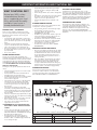
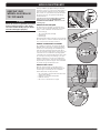
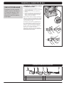
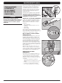
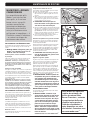
IMPORTANT INFORMATION ABOUT NATURAL GAS
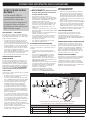
TYPICAL PIPE INSTALLATION
3 4 5 6 7
2
1
8
This is a typical installation of a Weber
®
natural gas grill. Local codes may require different installations.
INSIDE HOUSE OUTSIDE HOUSE
1 Gas supply 3 Quick-disconnect 6 1/2" pipe nipple
2 Shutoff 4 3/8" pipe nipple 7 Locking shutoff
5 Reducing coupling 8 Do not use
WHAT IS NATURAL GAS?
Natural gas (NG) is often
called methane. Natural
gas is supplied by your local
utility and should be readily
available if your house is
already heated with gas.
NATURAL GAS — THE BASICS
There are various guidelines and safety factors that
you need to keep in mind when using natural gas (NG).
Carefully follow these instructions before using your
Weber
®
gas grill.
• Yournaturalgasgrillisfactorybuilttooperateusing
natural gas only. Never attempt to operate your grill on
gases other than the type specied on the grill rating
plates.
• ThisWeber
®
gas grill is designed for natural gas
only. Do not use liquid propane (LP) bottled gas. The
valves, orices and hose are for natural gas only.
• BeforeusinganNGgrill,youneedtomakesurethat
the branch supply line from your house to your grill is
properly installed.
• Notforusebychildren.
PIPING SPECIFICATIONS
Contact your local municipality for building codes
regulating outdoor gas grill installations. In the absence of
local codes, installation must conform to the latest edition
of the National Fuel Gas Code: ANSI Z223.1/NFPA 54, or
CAN/CGA-B149.1, Natural Gas and Propane Installation
Code. WE RECOMMEND THAT THIS INSTALLATION BE
DONE BY A PROFESSIONAL.
Following are some general requirements taken from the
code(s).
• Thisgrillisdesignedtooperateat7"ofwatercolumn
pressure (.2526 psi).
• Amanualshutoffvalvemustbeinstalledoutdoors,
immediately prior to the quick-disconnect.
• Anadditionalmanualshutoffvalveshouldbeinstalled
indoors in the branch fuel line, in an accessible
location near the supply line.
• Thequick-disconnectconnectstoa3/8"NPTthread
from the gas source. The quick disconnect tting
is a hand-operated device that automatically shuts
off the ow of gas from the source when the grill is
disconnected.
• Thequick-disconnectttingcanbeinstalled
horizontally or pointing downward, but never pointing
upward. Installing it with the open end pointing upward
can result in water and debris collecting in the quick-
disconnect tting.
• Thedustcovers(plasticplugssuppliedwithyourgrill)
help keep the open ends of the quick-disconnect tting
clean while disconnected.
• Whenmakingconnections,onlyusepipecompound
that is resistant to the action of natural gas.
• Theoutdoorconnectormustbermlyattachedto
rigid, permanent construction.
m WARNING: Do not route the ten-foot
hose under a deck. The hose must be
visible.
• Forthecorrectsizeandlengthofgaslinepiping,refer
to the latest edition of the National Fuel Gas Code:
ANSI Z 223.1/NFPA 54, or CAN/CGA-B149.1, Natural
Gas and Propane Installation Code.
• Gaspipingmaybecoppertubing,typeKorL;
polyethylene plastic tube, with a minimum wall
thickness of .062"; or standard weight (schedule 40)
steel or wrought-iron pipe.
• Coppertubingmustbetinlinedifthegascontains
more than 0.3 grams of hydrogen sulde per 100
cubic feet of gas.
• Plastictubingissuitableonlyforoutdoor,underground
use.
• Gaspipingincontactwithearth,oranyothermaterial
which may corrode the piping, must be protected
against corrosion in an approved manner.
• Undergroundpipingmusthaveaminimumof18"
cover.
STORAGE AND/OR NONUSE
For grills that have been stored or left unused for a while,
it is important to follow these guidelines:
• Thegasmustbeturnedoffatthenaturalgassupply
when the Weber
®
gas grill is not in use.
• IfstoringtheWeber
®
gas grill indoors, rst
DISCONNECT the gas supply.
• TheWeber
®
gas grill should be checked for gas leaks
and any obstructions in the burner tubes before it is
used. (Refer to “ANNUAL MAINTENANCE.”)
• Checkthattheareasunderthecontrolpanelandthe
slide-out grease tray are free from debris that might
obstruct the ow of combustion or ventilation air.
• Thespider/insectscreensshouldalsobe
checked for any obstructions. (Refer to “ANNUAL
MAINTENANCE.”)
PRESSURE TESTING GAS SUPPLY
• DisconnectyourWeber
®
gas grill when the gas supply
is being tested at high pressures. This appliance and
its individual shutoff valve must be disconnected from
the gas supply piping system during any pressure
testing of that system at test pressures in excess of
1/2 psig (>3.5 kPa).
• TurnoffyourWeber
®
gas grill when the gas supply is
being tested at low pressures. This appliance must
be isolated from the gas supply piping system by
closing its individual manual shutoff valve during any
pressure testing of the gas supply piping system at test
pressures equal to or less than 1/2 psig (≤3.5 kPa).
CONNECTION TESTING
All connections and joints must be thoroughly tested
for leaks in accordance with local codes and all listed
procedures in the latest edition of the National Fuel Gas
Code: ANSI Z223.1/NFPA 54, or CAN/CGA-B149.1.
US INSTALLATION CODES
Installation must conform with local codes or, in the
absence of local codes, with either the National Fuel Gas
Code, ANSI Z223.1/NFPA 54, Natural Gas and Propane
Installation Code, CSA B149.1; or Propane Storage and
Handling Code, B149.2; or the Standard for Recreational
Vehicles, ANSI A 119.2/NFPA 1192, and CSA Z240 RV
Series, Recreational Vehicle Code, as applicable.
CANADIAN INSTALLATION
These instructions, while generally acceptable, do not
necessarily comply with the Canadian Installation codes,
particularly with piping above and below ground. In
Canada, the installation of this appliance must comply
with local codes and/or Standards CAN/CGA-B149.1
(Installation Code for Natural Gas Burning Appliances and
Equipment).

WWW.WEBER.COM
®
11
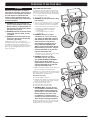
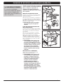
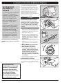
CONNECTING TO THE GAS SUPPLY
ALMOST READY TO GRILL
A quick-disconnect device
connects your grill to the gas
supply. After you have made
the connection, a leak check
will need to be performed.
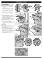
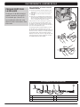
CONNECTING THE FLEXIBLE HOSE TO
GAS SUPPLY
A) Starting from inside the cabinet, route the exible gas
hose out of the opening in the rear panel (1).
B) Slide the collar of the quick-disconnect back (2).
C) Push male tting of the hose into the quick-disconnect
and maintain pressure. Slide the collar closed (3). If it
does not engage or lock, repeat procedure.
This procedure will produce a gas joint. Gas will not ow
unless the quick-disconnect is properly engaged. To
disconnect the hose, push collar back and pull out the
plug. (This automatically shuts off gas.)
The natural gas hose was attached during the
manufacturing process. We recommend that the
hose-to-gas manifold connection be leak tested, following
guidelines in this Owner’s Guide, prior to grill operation.
Note: Do not turn on gas source until you have performed
a leak check. Refer to “CHECKING FOR GAS LEAKS.”
1
2
3
NATURAL GAS HOSE CONNECTION
1 2 3 4 5 6
1 Shutoff valve 4 Dust covers
2 Pipe nipple 5 Male connection
3 Socket 6 Swivel connection

12 WWW.WEBER.COM
®
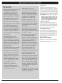
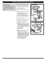
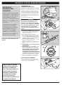
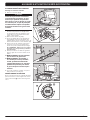
PREPARING TO USE YOUR GRILL
1
2
5
43
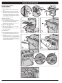
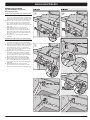
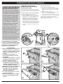
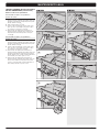
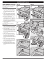
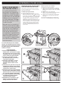
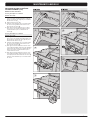
PARTIAL DISASSEMBLY OF YOUR GRILL
FOR A LEAK CHECK
In order to do the leak check, you need to have access
to the gas valves, which will require some simple grill
disassembly.
Conrm that Grill Is Off
A) Turn gas supply off at source.
B) Check that ALL burner control knobs are in the off (
)
position (1). Control knobs are shipped in the off ( )
position, but you should check to be sure that they
are turned off. Check by pushing control knobs in and
turning them clockwise. If they do not turn, they are
off. If they do turn, continue turning them clockwise
until they stop; then they are off. If your grill has a side
burner, make sure the side burner control knob is
turned off.
Remove Control Panel
You will need: A Phillips screwdriver.
A) Disconnect the two wires from the igniter button
located on the underside of the control panel (2).
NOTE: Pull from terminals at ends of wires.
B) Remove control knobs (3).
C) Remove the screws from the front of the control panel
with a Phillips screwdriver (4).
D) Carefully lift control panel up and then pull forward
away from frame (5).
Your grill is now ready for a leak check. Proceed to
“CHECKING FOR GAS LEAKS.”
WHAT IS A LEAK CHECK?
The fuel system in your grill
features many connections
and fittings. A leak check is a
reliable way to make sure that
no gas is escaping from any of
the connections or fittings.
Although all factory-made
connections have been
thoroughly checked for
gas leaks, it’s important to
perform a leak check before
using your grill for the first
time, as well as anytime you
disconnect and reconnect
a fitting and each time you
perform routine maintenance.
Safety must be considered when you are
deciding where to place and operate your
grill. Be sure to read the following warnings
before installing or using your grill.
WARNINGS:
m Only use this grill outdoors in a well-
ventilated area. Do not use in a garage,
building, breezeway or any other
enclosed area.
m Your Weber
®
gas grill shall not be
used beneath overhead combustible
construction.
m Your Weber
®
gas grill is not intended
to be installed in or on recreational
vehicles and/or boats.
m Do not use the grill within 24 inches of
combustible materials. This includes
the top, bottom, back or sides of the
grill.
m Keep the cooking area clear of
ammable vapors and liquids such
as gasoline, alcohol, etc., and
combustible materials.
m The entire cookbox gets hot when in
use. Do not touch.
m Do not move the Weber
®
gas grill when
operating or while grill is hot.

WWW.WEBER.COM
®
13
PREPARING TO USE YOUR GRILL
m DANGER
Do not use an open ame to check for
gas leaks. Be sure there are no sparks or
open ames in the area while you check
for leaks. Sparks or open ames will
result in a re or explosion, which can
cause serious bodily injury or death and
damage to property.
m WARNING: The gas connections of
your gas grill have been factory tested.
We do, however, recommend that you
leak check all gas connections before
operating your gas grill.
m WARNING: Perform these leak checks
even if your grill was dealer or store
assembled.
m WARNING: You should check for gas
leaks every time you disconnect and
reconnect a gas tting.
NOTE: All factory-made connections have been
thoroughly checked for gas leaks and the burners have
been ame-tested. As a safety precaution, however,
you should check all ttings for leaks before using your
Weber® gas grill. Shipping and handling may loosen or
damage a gas tting.
4
2
3
1
6
5
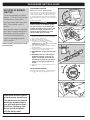
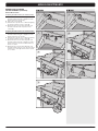
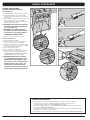
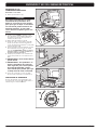
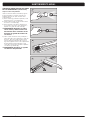
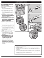
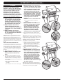
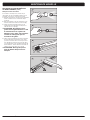
CHECKING FOR GAS LEAKS
You will need: A spray bottle or brush or rag and a soap
and water solution. (You can make your own soap and
water solution by mixing 20% liquid soap with 80% water;
or, you can purchase leak check solution in the plumbing
section of any hardware store.)
A) Turn gas supply on at source (1).
m WARNING: Do not ignite burners when
leak checking.
B) To check for leaks, wet ttings with the soap and water
solution, using a spray bottle, brush or rag. If bubbles
form, or if a bubble grows, there is a leak. Apply the
soap and water solution to the following connections:
a) Flexible hose-to-bulkhead connection (2).
b) Corrugated manifold hose-to-bulkhead
connection(3).
c) Corrugated manifold hose-to-manifold
connection(4).
m WARNING: If there is a leak at
connections (2, 3 or 4), turn off the
gas, tighten the tting with a wrench,
and recheck for leaks with soap and
water solution. If a leak persists
after tightening the tting, turn off
the gas. DO NOT OPERATE THE
GRILL. Contact the Customer Service
Representative in your area using the
contact information on our web site.
Log onto www.weber.com
®
.
d) Flexible hose-to-quick-disconnect connection (5).
e) Valves-to-manifold connections (6).
m WARNING: If there is a leak at
connections (5 or 6), turn off the
gas. DO NOT OPERATE THE GRILL.
Contact the Customer Service
Representative in your area using the
contact information on our web site.
Log onto www.weber.com
®
.
C) When leak checking is complete, turn gas supply off at
the source and rinse connections with water.
NOTE: Since some leak test solutions, including soap and
water, may be slightly corrosive, all connections should be
rinsed with water after checking for leaks.
Reinstall Control Panel
You will need: A Phillips screwdriver.
A) Align valve stems with holes in control panel. Position
top edge of control panel on tabs of frame assembly.
Push control panel down into position.
B) Fasten control panel with screws.
C) Place control knobs onto valve stems.
D) Connect the wires to the igniter button.
m WARNING: Make sure that all parts
are assembled and hardware is fully
tightened before operating the grill.
Your actions, if you fail to follow this
product warning, may cause a re,
an explosion, or structural failure
resulting in serious personal injury or
death as well as damage to property.
Now that the grill has been leak checked and gas supply
has been installed and checked for leaks in accordance
with the instructions, you are ready to grill.

14 WWW.WEBER.COM
®
GRILLING TIPS & HELPFUL HINTS
PREHEATING
Preheating the grill before grilling is important. To
preheat: Light your grill according to the instructions in
the Owner’s Guide; then turn all burners to start/high ( )
position, close the lid, and preheat until the temperature
reaches between 500° and 550°F (260° and 290°C), the
recommended broiling temperature. This will take 10 to 15
minutes depending on conditions such as air temperature
and wind. After preheating, you can adjust the individual
burners as desired.
m WARNING: Should the burners go out
while grill is in operation, turn all gas
valves off. Open the lid and wait ve
minutes before attempting to relight
grill, using the igniting instructions.
COVERED COOKING
All grilling is done with the lid down to provide uniform,
evenly circulated heat. With the lid closed, the gas grill
cooks much like a convection oven. The thermometer in
the lid indicates the cooking temperature inside the grill.
All preheating and grilling is done with the lid down. No
peeking — heat is lost every time you lift the lid.
FLAVORIZER
®
SYSTEM
The closed lid and Flavorizer
®
bars produce that
“outdoor” avor in the food. When meat juices drip from
the food onto the specially angled Flavorizer
®
bars, they
create smoke that gives foods an irresistible barbecued
avor. Thanks to the unique design of the burners, the
Flavorizer
®
bars, and the exible temperature controls,
uncontrolled are-ups are virtually eliminated, because
YOU control the ames.
DRIPPINGS AND GREASE
Because of the special design of the Flavorizer
®
bars
and burners, excess fats are directed down the slide-out
grease tray and into the catch pan. Disposable drip pans
that t the catch pan are available.
TIPS & HINTS
•Alwayspreheatthegrillbefore
cooking. Set all burners
on high heat and close lid;
preheat for 10 minutes, or
until thermometer registers
500°–550°F (260° – 290°C).
•Thetemperatureofyourgas
grill may run hotter than
normal for the first few uses.
•Recipegrillingtimesarebased
on outside temperatures of
70°F (20°C) and little or no
wind. Allow for more cooking
time on cold or windy days, or
at higher altitudes. Allow for
less cooking time in extremely
hot weather.
•Grillingconditionsmay
require adjustment of the
burner controls to attain the
correct cooking temperatures.
•Searmeatsandcookwiththe
lid down for perfectly grilled
food every time.
•Crowdingfoodontoacooking
grate means more time will
be required to cook the food.
•Trimexcessfatfromsteaks,
chops, and roasts, leaving
no more than a scant ¼ inch
(6.4mm) of fat. Less fat
makes cleanup easier, and is
a virtual guarantee against
unwanted flare-ups.
•Ingeneral,largepieces
of meat will require more
cooking time per pound than
small pieces of meat.
•Somefoods,suchasa
casserole or thin fish fillets,
will require a container for
grilling. Disposable foil pans
are very convenient, but any
metal pan with ovenproof
handles can also be used.
•Foodsincontainers,such
as baked beans, will require
more time if grilled in a deep
casserole than in a shallow
baking pan.
•Foodsplacedonthecooking
grate directly above burners
may require turning or moving
to a less hot area.
•Usetongsratherthanafork
for turning and handling
meats to avoid losing natural
juices.Usetwospatulasfor
handling large whole fish.
•Alwaysbesuretheslide-out
grease tray and catch pan are
clean and free from debris.
•Donotlinetheslide-out
grease tray with foil. This
could prevent the grease from
flowing into the catch pan.
•Ifanunwantedflare-up
should occur, turn all burners
off and move food to another
area of the cooking grate. Any
flames will quickly subside.
After flames subside, relight
thegrill.NEVERUSEWATER
TOEXTINGUISHFLAMESON
AGASGRILL.
•Usingatimerwillhelptoalert
you when “well done” is about
to become “overdone.”

WWW.WEBER.COM
®
15
SAFETY CHECKS BEFORE USING YOUR GRILL
When you are getting ready to grill, your
rst thought should always be safety.
Following are a few safety checks that
you should perform each time you grill.
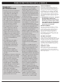
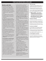
SLIDE-OUT GREASE TRAY
Your grill was built with a grease collection system,
which funnels grease away from food and into removable
containers.
Check the slide-out grease tray for grease build-up each
time you use your grill. Remove excess grease with a
plastic scraper (1). Wash the grease tray with a soap and
water solution and rinse with water.
m CAUTION: Do not line the slide-out
grease tray with aluminum foil.
CATCH PAN AND DISPOSABLE DRIP PAN
Grease from the slide-out grease tray funnels into a
catch pan. Cleaning the catch pan is just as important as
cleaning the slide-out grease tray.
Check the catch pan for grease build-up each time you
use your grill. Remove excess grease with a plastic
scraper (2). Wash the catch pan with warm, soapy water
and rinse with water. To keep the catch pan cleaner
longer, you can line the catch pan with a Weber
®
disposable drip pan or with aluminum foil.
m WARNING: Check the slide-out grease
tray and catch pan for grease build-
up before each use. Remove excess
grease to avoid a grease re. A grease
re can cause serious bodily injury or
damage to property.
HOSE INSPECTION
The hose should be inspected routinely for any signs of
cracking (3).
m WARNING: Check hose before each
use of grill for nicks, cracking,
abrasions or cuts. If the hose is found
to be damaged in any way, do not use
the grill. Replace using only Weber
®
authorized replacement hose. Contact
the Customer Service Representative
in your area using the contact
information on our web site.
Log onto www.weber.com
®
.
SAFETY FIRST
It’ssensibleandsmarttoget
in the habit of performing
a few safety checks before
grilling.
2
3
1
2
4
3

16 WWW.WEBER.COM
®
Summary lighting instructions are inside
the cabinet door.
MAIN BURNER IGNITION & USAGE
2
5
1
4
3
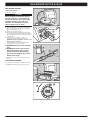
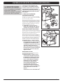
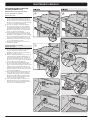
MAIN BURNER IGNITION
Electronic Crossover
®
Ignition System
The electronic Crossover
®
ignition system ignites burner
1 with a spark from the igniter electrode inside the Gas
Catcher™ ignition chamber. You generate the energy for
the spark by pushing the igniter button. You will hear the
igniter clicking. Burner(s) 2 (and 3) can be lit after burner1
is lit.
A) Open the grill lid (1).
m DANGER
Failure to open the lid before igniting
the grill’s burners, or not waiting ve
minutes to allow the gas to clear if the
grill does not light, may result in an
explosive are-up which can cause
serious bodily injury or death.
B) Make sure ALL burner control knobs are turned off
(2). Check by pushing control knobs in and turning
them clockwise until they stop.
C) Turn the gas supply valve on (3).
D) Push burner 1 control knob in and turn it
counterclockwise to start/high ( ) position (4).
IMPORTANT: Always ignite burner 1 rst. The other
burner(s) ignite from burner 1.
E) Push and hold in the igniter button (5). You will hear
the igniter clicking.
F) Check that burner 1 is lit by looking through the
cooking grates. You should see a ame.
m WARNING: Do not lean over the open
grill.
m WARNING: If burner 1 fails to ignite
within ve seconds, stop, turn the
burner control knob to off and wait
ve minutes to allow the gas to clear
before you try again or light with a
match.
G) After burner 1 is lit, you can turn on burner 2 (and
burner 3).
TO EXTINGUISH BURNER
Push each burner control knob in and turn it clockwise to
the off ( ) position. Turn gas supply off at the source.
METHODS OF BURNER
IGNITION
There are two ways to ignite
burner 1. The first is by using
the electronic Crossover
®
ignition system built into your
grill. The second is with a
match.
Next are the steps for igniting
your grill using the electronic
Crossover
®
ignition system.
On the following page are
steps for igniting your grill
with a match.
Some batteries have a plastic
protective wrap around them.
This plastic must be removed
before you attempt to ignite
your grill with the electronic
Crossover
®
ignition system.
Do not confuse this plastic
with the battery label.

WWW.WEBER.COM
®
17
MAIN BURNER IGNITION
Lighting with a Match
A) Open the grill lid (1).
m DANGER
Failure to open the lid before igniting
the grill’s burners, or not waiting ve
minutes to allow the gas to clear if the
grill does not light, may result in an
explosive are-up which can cause
serious bodily injury or death.
B) Make sure ALL burner control knobs are turned off
(2). Check by pushing control knobs in and turning
them clockwise until they stop.
C) Turn the gas supply valve on (3).
D) Put match in the matchstick holder and strike match.
Insert matchstick holder with lit match down through
the cooking grates, past the Flavorizer
®
bars and next
to burner1 (4).
E) Push burner 1 control knob in and turn it
counterclockwise to start/high ( ) position (5).
IMPORTANT: Always ignite burner 1 rst. The other
burner(s) ignite from burner 1.
F) Check that burner 1 is lit by looking through the
cooking grates. You should see a ame.
m WARNING: Do not lean over the open
grill.
m WARNING: If burner 1 fails to ignite
within ve seconds, stop, turn the
burner control knob to off and wait
ve minutes to allow the gas to clear
before you try again.
G) After burner 1 is lit, you can turn on burner 2 (and
burner 3).
TO EXTINGUISH BURNER
Push each burner control knob in and turn it clockwise to
the off ( ) position. Turn gas supply off at the source.
1
2
4
3
5
MAIN BURNER IGNITION & USAGE

18 WWW.WEBER.COM
®
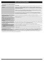
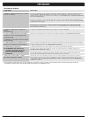
TROUBLESHOOTING
GENERAL TROUBLESHOOTING
PROBLEMS SOLUTIONS
Burner does not ignite when you push the igniter
button.
Be sure that there is gas ow to the burners by attempting to match light your burners. Refer to “MAIN BURNER
IGNITION—Lighting with a Match.” If match lighting is successful, the problem lies in the ignition system. Refer to
“MAINTAINING THE ELECTRONIC CROSSOVER
®
IGNITION SYSTEM.”
Be sure that wires are correctly inserted into terminals on igniter module. Check that the wires are connected to
terminals on igniter button under the control panel. Refer to “IGNITER MODULE WIRE GUIDE.”
If a new battery is installed, conrm that battery’s plastic wrapping has been removed. Verify that the battery is in good
condition and has been installed correctly. Refer to “MAINTAINING THE ELECTRONIC CROSSOVER
®
IGNITION
SYSTEM.”
Burner does not ignite, or ame is low in
high (
) position.
Fuel hose could be bent or kinked. Straighten fuel hose.
Burner ame pattern is erratic.
Flame is low when burner is on high (
) position.
Flames do not run the whole length of the
burnertube.
Clean burner ports that run down the entire length of burner tube. Refer to “ANNUAL MAINTENANCE.”
Burners burn with a yellow or orange ame, in
conjunction with the smell of gas.
Inspect spider/insect screens for possible obstructions. (Blockage of holes.) Clean spider/insect screens.
Refer to “ANNUAL MAINTENANCE.”
Experiencing are-ups.
m CAUTION: Do not line the slide-out
grease tray with aluminum foil.
Grill must be preheated with all burners on high for 10 to 15 minutes.
Clean the cooking grates and Flavorizer
®
bars thoroughly to remove grease. Refer to “ROUTINE MAINTENANCE.”
The slide-out grease tray may be dirty and is not allowing grease to ow into catch pan. Clean slide-out grease tray.
Inside of lid appears to be “peeling.”
(Resembles paint peeling.)
The inside of the lid is porcelain enamel or stainless steel. It is not painted. It cannot “peel.” What you are seeing is
baked-on grease that has turned to carbon and is aking off. THIS IS NOT A DEFECT. Clean thoroughly. Refer to
“ROUTINE MAINTENANCE.”
If problems cannot be corrected by using these methods, please contact the Customer Service Representative in your area using the contact information on our
web site. Log onto www.weber.com
®
.

WWW.WEBER.COM
®
19
ANNUAL MAINTENANCE
KEEPING YOUR
WEBER
®
GAS GRILL IN
TIP-TOP SHAPE
m DANGER
Failure to correct any problems described
on this page may result in a re, which
can cause serious bodily injury or death,
and cause damage to property.
To keep your Weber
®
gas grill performing as safely and
efficiently as on day one, we strongly recommend that you
inspect and clean the spider/insect screens and burner
tubes at least once a year. Below is important information
about these two areas of the grill that should undergo
annual maintenance.
If you observe an incorrect ame pattern or blocked
burner ports, proceed to the “BURNER TUBE
CLEANING OR REPLACEMENT” instructions on the
following pages.
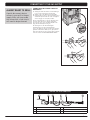
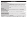
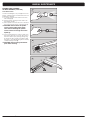
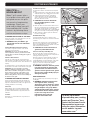
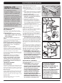
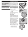
BURNER FLAME PATTERN
The burner tubes in your Weber
®
gas grill were factory
set for the correct air and gas mixture. The correct ame
pattern is shown in illustration and described below:
• Burnertube(1)
• Tipsoccasionallyickeryellow(2)
• Lightblue(3)
• Darkblue (4)
Check burner ame pattern. If the ames do not match the
above description, it could be an indication that the spider/
insect screens have become dirty or blocked.
WEBER
®
SPIDER/INSECT SCREENS
The combustion air openings of the burner tubes (5) are
tted with stainless steel screens to help prevent spiders
and other insects from spinning webs and building nests
inside the venturi section (6) of the burner tubes. These
nests can obstruct the normal gas ow, and can cause gas
to ow back out of the combustion air openings (7). This
could result in a re in and around the burner valves, under
the control panel, causing serious damage to your grill.
NOTE: If a spider/insect screen becomes damaged or
cannot be cleaned, please contact the Customer Service
Representative in your area using the contact information
on our web site. Log onto www.weber.com®.
BURNER TUBE PORTS
Over time, from repeated use of the grill, the burner
tube ports will become dirty. Blocked and dirty ports can
restrict full gas ow. Following are ways to determine
whether burner tubes are dirty or blocked.
• Gasissmelledinconjunctionwithburneramesthat
appear yellow and lazy
• Grilldoesnotreachdesiredtemperature
• Grillheatsunevenly
• Oneormoreoftheburnersdonotignite
6
5
7
2
3
4
1

20 WWW.WEBER.COM
®
ANNUAL MAINTENANCE
9
8
7
5
43
6
1
2
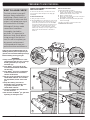
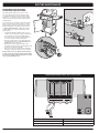
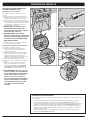
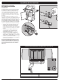
BURNER TUBE CLEANING
OR REPLACEMENT
Conrm that Grill Is Off
A) Turn gas supply off at source and disconnect gas
tting.
B) Check that all burner control knobs are in the off
( )position. Check by pushing control knobs in and
turning them clockwise until they stop. If they do not
turn, they are already off. If they do turn, continue
turning them clockwise until they stop; then they are
off. If your grill has a side burner, make sure the side
burner control knob is turned off.
Remove Control Panel
You will need: A Phillips screwdriver.
A) Open cabinet door. Remove igniter wires from wire
clips on the inside left panel (1). Disconnect wires
from igniter module inside the cabinet(2).
NOTE: Do not disconnect by pulling on wires; pull
from terminals at ends of wires.
B) Remove cookbox components(3).
C) Remove control knobs(4).
D) Remove screws from the front of the control panel
with a Phillips screwdriver(5).
E) Carefully lift control panel up and then pull forward and
away from cookbox(6).
Remove Manifold
Youwillneed:APhillipsscrewdriver,two7/16"wrenches.
A) With the Phillips screwdriver, remove two screws
and two washers attaching manifold to front cross
brace(7).
B) Usingtwo7/16"wrenches,removetwoboltsandtwo
nuts attaching manifold to cookbox (8). Pull manifold
forward and away from burner tubes (9). Manifold will
remain attached to corrugated gas line(s). Be careful
not to let manifold scratch frame or door or kink the
attached corrugated gas line(s).
La page est en cours de chargement...
La page est en cours de chargement...
La page est en cours de chargement...
La page est en cours de chargement...
La page est en cours de chargement...
La page est en cours de chargement...
La page est en cours de chargement...
La page est en cours de chargement...
La page est en cours de chargement...
La page est en cours de chargement...
La page est en cours de chargement...
La page est en cours de chargement...
La page est en cours de chargement...
La page est en cours de chargement...
La page est en cours de chargement...
La page est en cours de chargement...
La page est en cours de chargement...
La page est en cours de chargement...
La page est en cours de chargement...
La page est en cours de chargement...
La page est en cours de chargement...
La page est en cours de chargement...
La page est en cours de chargement...
La page est en cours de chargement...
La page est en cours de chargement...
La page est en cours de chargement...
La page est en cours de chargement...
La page est en cours de chargement...
La page est en cours de chargement...
La page est en cours de chargement...
La page est en cours de chargement...
La page est en cours de chargement...
La page est en cours de chargement...
La page est en cours de chargement...
La page est en cours de chargement...
La page est en cours de chargement...
La page est en cours de chargement...
La page est en cours de chargement...
La page est en cours de chargement...
La page est en cours de chargement...
La page est en cours de chargement...
La page est en cours de chargement...
La page est en cours de chargement...
La page est en cours de chargement...
La page est en cours de chargement...
La page est en cours de chargement...
La page est en cours de chargement...
La page est en cours de chargement...
La page est en cours de chargement...
La page est en cours de chargement...
La page est en cours de chargement...
La page est en cours de chargement...
-
 1
1
-
 2
2
-
 3
3
-
 4
4
-
 5
5
-
 6
6
-
 7
7
-
 8
8
-
 9
9
-
 10
10
-
 11
11
-
 12
12
-
 13
13
-
 14
14
-
 15
15
-
 16
16
-
 17
17
-
 18
18
-
 19
19
-
 20
20
-
 21
21
-
 22
22
-
 23
23
-
 24
24
-
 25
25
-
 26
26
-
 27
27
-
 28
28
-
 29
29
-
 30
30
-
 31
31
-
 32
32
-
 33
33
-
 34
34
-
 35
35
-
 36
36
-
 37
37
-
 38
38
-
 39
39
-
 40
40
-
 41
41
-
 42
42
-
 43
43
-
 44
44
-
 45
45
-
 46
46
-
 47
47
-
 48
48
-
 49
49
-
 50
50
-
 51
51
-
 52
52
-
 53
53
-
 54
54
-
 55
55
-
 56
56
-
 57
57
-
 58
58
-
 59
59
-
 60
60
-
 61
61
-
 62
62
-
 63
63
-
 64
64
-
 65
65
-
 66
66
-
 67
67
-
 68
68
-
 69
69
-
 70
70
-
 71
71
-
 72
72


Weber E210 Manuel utilisateur
- Catégorie
- Barbecues
- Taper
- Manuel utilisateur
- Ce manuel convient également à
dans d''autres langues
- English: Weber E210 User manual
- español: Weber E210 Manual de usuario
Documents connexes
-
Weber 46810001 Mode d'emploi
-
-
-
-
-
-
-
-
-
Weber 89963 Manuel utilisateur