Kobe Range Hoods CH7930SQB Manuel utilisateur
- Catégorie
- Hottes
- Taper
- Manuel utilisateur
Ce manuel convient également à

KOBE Brand Range Hood
Model No. / N
os
de modèles / Modelo No.
CH7930SQB
CH7936SQB
CH7942SQB
CH7948SQB
CH-179 SERIES – 9” HEIGHT
INSTALLATION INSTRUCTIONS
AND OPERATION MANUAL
MANUEL D'INSTALLATION
ET MODE D'EMPLOI
INSTRUCCIONES DE INSTALACIÓN
Y MANUAL DE OPERACIÓN

[ENGLISH] ...................................................................................................................... 1
[FRENCH] ..................................................................................................................... 34
[SPANISH] .................................................................................................................... 67

1
[ENGLISH]
- READ AND SAVE THESE INSTRUCTIONS -
CONTENTS
IMPORTANT SAFETY INSTRUCTIONS ......................................................................... 2
COMPONENTS OF PACKAGE ....................................................................................... 4
INSTALLATION ............................................................................................................... 5
OPERATING INSTRUCTIONS...................................................................................... 18
MAINTENANCE ............................................................................................................ 19
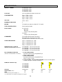
SPECIFICATIONS ......................................................................................................... 21
MEASUREMENTS & DIAGRAMS................................................................................. 22
PARTS LIST .................................................................................................................. 24
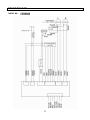
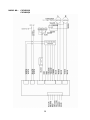
CIRCUIT DIAGRAM ...................................................................................................... 27
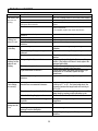
TROUBLE SHOOTING ................................................................................................. 29
DISCLAIMER ................................................................................................................ 30
WARRANTY .................................................................................................................. 31
PRODUCT REGISTRATION ......................................................................................... 33
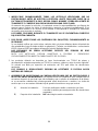
- READ ALL INSTRUCTIONS CAREFULLY BEFORE STARTING -
ALL WIRING MUST BE DONE BY A PROFESSIONAL AND IN
ACCORDANCE WITH NATIONAL AND LOCAL ELECTRICAL CODES

2
IMPORTANT SAFETY INSTRUCTIONS
- PLEASE READ THIS SECTION CAREFULLY BEFORE INSTALLATION -
WARNING: TO REDUCE THE RISK OF FIRE, ELECTRIC SHOCK OR PERSONAL
INJURY, OBSERVE THE FOLLOWING:
1) Installation and electrical wiring must be done by qualified professionals and in accordance
with all applicable codes and standards, including fire-rated construction.
2) When cutting or drilling into wall or ceiling, be careful not to damage electrical wiring or
other hidden utilities.
3) Ducted fans must be vented to the outside.
a) Before servicing or cleaning unit, open the light panel and SWITCH POWER OFF AT
SERVICE PANEL.
b) Clean all grease laden surfaces frequently. To reduce the risk of fire and to disperse air
properly, make sure to vent air outside. DO NOT vent exhaust air into wall spaces,
attics, crawl spaces or garages.
NOTE
-
This warranty is void without an authorized agent’s receipt or if
unit is damaged due to misuse, poor installation, improper use,
mistreatment, negligence or any other circumstances beyond the
control of KOBE RANGE HOODS authorized agents. Any repair
carried out without the supervision of KOBE RANGE HOODS
authorized agents will automatically void the warranty.
-
KOBE RANGE HOODS will not be held responsible for any
damages to personal property or real estate or any bodily injuries
whether caused directly or indirectly by the range hood.
WARNING: TO REDUCE THE RISK OF PERSONAL INJURY IN THE EVENT OF A
RANGE TOP GREASE FIRE:
1. Keep all fan, baffle/spacer/filter/oil tunnel/oil container and grease-laden surfaces clean.
Grease should not be allowed to accumulate on fan, baffle/spacer/filter/oil tunnel/oil
container.
2. Always turn hood ON when cooking.
3. Use high settings on cooking range ONLY when necessary.
4. Do not leave cooking range unattended when cooking.
5. Always use cookware and utensils appropriate for the type and amount of food prepared.
6. Use this unit only in the manner intended by the manufacturer.
7. Before servicing, switch power off at service panel and lock service panel (if possible) to
prevent power from switching on accidentally.
8. Clean ventilating fan frequently.

3
• SMOTHER FLAMES with a tight fitting lid, cookie sheet, or metal tray, and then turn off the
burner. KEEP FLAMMABLE OR COMBUSTIBLE MATERIAL AWAY FROM FLAMES. If
the flames do not go out immediately, EVACUATE THE AREA AND CALL THE FIRE
DEPARTMENT or 911.
What to Do In The Event Of a Range Top Grease Fire
• NEVER PICK UP A BURNING PAN – You May Get Burned.
• DO NOT USE WATER, including wet dishcloths or towels – a steam blast will result.
• Use an extinguisher ONLY if:
a) You have a Class A, B, C extinguisher and know how to operate it.
b) The fire is small and contained in the area where it started.
c) The fire department has been called.
d) You can fight the fire with your back to an exit.
- Extinguish any open flame.
What to Do If You Smell Gas
- Do not try to turn on the lights or any type of appliance.
- Open all doors and windows to disperse the gas. If you still smell gas, call the Gas
Company and Fire Department right away.
CAUTION
1) For general ventilation use only. Do not use to exhaust hazardous or explosive materials
and vapors.
2) To reduce the risk of fire, use only metal ductwork. Sufficient air is needed for proper
combustion and exhausting of gases through the flue (chimney) to prevent back drafting.
3) Follow the heating equipment manufacturer’s guideline and safety standards such as those
published by the National Fire Protection Association (NFPA), and the American Society for
Heating, Refrigeration and Air Conditioning Engineers (ASHRAE), and code authorities.
4) Activating any switch on may cause ignition or an explosion.
5) Due to the size and weight of this hood, installation by 2 persons is recommended.
ELECTRICAL SHOCK HAZARD – Can result in serious injury or
death. Disconnect appliance from electric power before servicing.
If equipped, the fluorescent light bulb contains small amounts of
mercury, which must be recycled or disposed of according to
Local, State, and Federal Codes.

4
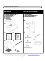
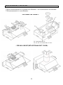
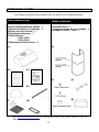
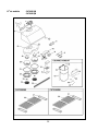
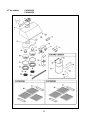
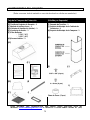
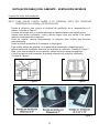
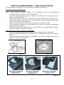
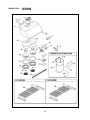
COMPONENTS OF PACKAGE
(Must keep all material for returns or refunds)
- FOR MORE INFORMATION, PLEASE VISIT OUR WEBSITE www.KOBERangeHoods.com OR
CONTACT KOBE RANGE HOODS AT (626) 775-8880.
Range Hood Box
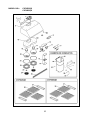
Duct Cover Box (Sold Separately)
{A} KOBE Range Hood – 1
{B} Warranty Registration Card – 1
{C} Instructions Manual – 1
{D} Vent Cover (Top) – 1
{E} Oil Tunnel – 1
{F} Baffle Filters
- 2 (30” & 36”)
- 3 (42” & 48”)
{G} Bottom Casing – 2
{A}
{B} {C}
{D} {E}
{F} {G}
{H} Adjustable Duct Cover - 1
{I} Screws Package – 1
{J} Duct Cover-Mounting Bracket – 1
{K} Hood-Mounting Bracket – 1
{H}
{I} {J}
{K}

5
INSTALLATION
PLEASE READ ENTIRE INSTRUCTIONS BEFORE PROCEEDING
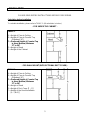
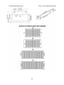
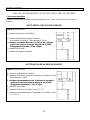
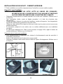
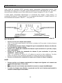
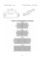
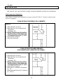
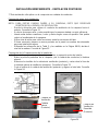
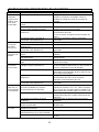
TABLE 1
A = Height of Floor to Ceiling
B = Height of Floor to Counter Top
(Standard: 36")
C = Preferred Height of Counter Top
to Hood Bottom (Minimum
27" to 30")
D = Height of Hood
E = Height of the Cabinet
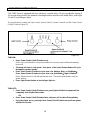
Calculation before Installation
To calculate installation, please refer to TABLE 1. (All calculation in inches.)
- FOR UNDER THE CABINET -
- FOR WALL MOUNT (WITH OPTIONAL DUCT COVER) -
TABLE 2
A = Height of Floor to Ceiling
B = Height of Floor to Counter Top
(Standard: 36")
C = Preferred Height of Counter Top
to Hood Bottom (Minimum
27" to 30")
D = Height of Hood
E = Height of Duct Cover [F – D]
F = Height of the Hood Installation
[A – (B+C)]

6
SAFETY WARNING
HOOD MAY HAVE VERY SHARP EDGES; PLEASE WEAR PROTECTIVE GLOVES IF
REMOVING ANY PARTS FOR INSTALLING, CLEANING OR SERVICING.
NOTE: BE CAREFUL WHEN USING ELECTRICAL SCREWDRIVER, DAMAGE TO THE HOOD
MAY OCCUR.
UNDER THE CABINET
Top Vent…………………………………………………………………………………
Rear Vent………………………………………………………………………………..
WALL MOUNT
Top Vent…………………………………………………………………………………
Rear Vent………………………………………………………………………………..
Installation Contents
7
9
11
14

7
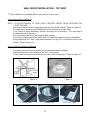
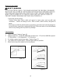
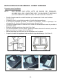
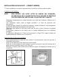
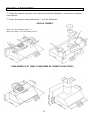
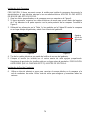
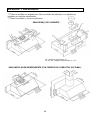
UNDER THE CABINET INSTALLATION – TOP VENT
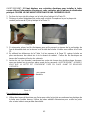
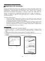
- Decide the location of the venting pipe from the hood to the outside. Refer to Figure 1.
Preparation before Installation
NOTE: TO AVOID DAMAGE TO YOUR HOOD, PREVENT DEBRIS FROM ENTERING THE
VENT OPENING.
- A straight, short venting run will allow the hood to perform more efficiently.
- Try to avoid as many transitions, elbows, and long run as possible. This may reduce
the performance of the hood.
- Temporarily wire the hood to test for proper operation before installing.
- Peel protective film off the hood (if any).
- For installing under the cabinet with recessed bottom, attach 4-inch wide wood filler
strips (not included) on each side. Refer to Figure 2.
- Measure and create access opening for electrical wires under the cabinet.
- Cut the multi duct exhaust according to the size of the venting pipe. Refer to Figure 3.
Figure 1 Figure 2
6" Round Vent 7" Round Vent 3-1/4" x 10" Vent
Figure 3

8
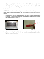
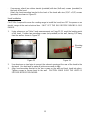
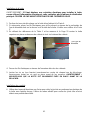
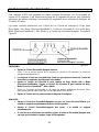
2. If necessary, arrange the electrical wires to run through the 1” diameter hole on the top or
the rear of the hood. Refer to Figure 5.
Hood Installation
CAUTION: If required to move the cooking range to install the hood, turn off the power on an
electric range at the main electrical box. SHUT OFF THE GAS BEFORE MOVING A GAS
RANGE.
1. Puncture the knockout holes on the hood as shown in Figure 4.
3. Using references on Table 1 and measurements on Page 22 to center the hood in place
beneath the cabinet and flush with the front of the cabinet.
1" Diameter
Hole
Figure 4 Figure 5
4. Draw electrical wires through cabinet access opening.
5. Place screw (not provided) into the exact center of each knockout hole. Make sure all
screws are in place before tightening screws. CAUTION: MAKE SURE THE HOOD IS
SECURE BEFORE RELEASING.
6. Use aluminum or steel pipe to connect the plastic exhaust on the hood to the ductwork
above. Use duct tape to make all joints secure and air tight.
Ductwork Installation

9
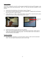
UNDER THE CABINET INSTALLATION – REAR VENT
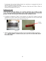
- Decide the location of the venting pipe from the hood to the outside. Refer to Figure 6.
Preparation before installation
NOTE: TO AVOID DAMAGE TO YOUR HOOD, PREVENT DEBRIS FROM ENTERING THE
VENT OPENING.
- A straight, short venting run will allow the hood to perform more efficiently.
- Try to avoid as many transitions, elbows, and long run as possible. This may reduce
the performance of the hood.
- Temporarily wire the hood to test for proper operation before installing.
- Peel protective film off the hood (if any).
- For installing under the cabinet with recessed bottom, attach 4-inch wide wood filler
strips (not included) on each side. Refer to Figure 7.
- Measure and create access opening for electrical wires under the cabinet or access
opening for the electrical wires at the rear of the hood.
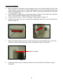
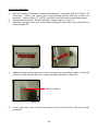
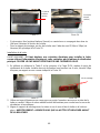
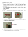
- Remove the screws on the vent cover (rear) and cut along the line of the inner vent
cover (rear) opening. Refer to Figure 8.
- Cut the vent cover (rear) opening and reverse to the other side. Refer to Figure 9.
Reattach the vent cover (rear).
Figure 6 Figure 7
Inner Vent Reversed
Cover (Rear) Vent Cover
(Rear)
Figure 8 Figure 9

10
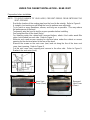
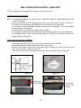
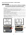
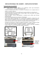
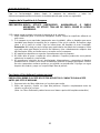
1. Puncture the knockout holes on the hood as shown in Figure 10.
Hood Installation
CAUTION: If required to move the cooking range to install the hood, turn off the power on an
electric range at the main electrical box. SHUT OFF THE GAS BEFORE MOVING A GAS
RANGE.
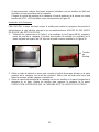
2. Unscrew and remove the multi duct exhaust. Replace with {D} vent cover (top). Refer to
Figure 11.
Figure 10 Figure 11
3. If necessary, arrange the electrical wires to run through the 1” diameter hole on the top or
the rear of the hood. Refer to Figure 12.
4. Using references on Table 1 and measurements on Page 22 to center the hood in place
beneath the cabinet and flush with the front of the cabinet.
5. Place screw (not provided) into the exact center of each knockout hole. Make sure all
screws are in place before tightening screws. CAUTION: MAKE SURE THE HOOD IS
SECURE BEFORE RELEASING.
1” Diameter Hole
Figure 12
6. Use aluminum or steel pipe to connect the exhaust opening at the rear of the hood to the
ductwork. Use duct tape to make all joints secure and air tight.
Ductwork Installation

11
WALL MOUNT INSTALLATION – TOP VENT
***This installation only applied with the purchase of a duct cover.
- Decide the location of the venting pipe from the hood to the outside. Refer to Figure 13.
Preparation before Installation
NOTE: TO AVOID DAMAGE TO YOUR HOOD, PREVENT DEBRIS FROM ENTERING THE
VENT OPENING.
- A straight, short venting run will allow the hood to perform more efficiently.
- Try to avoid as many transitions, elbows, and long run as possible. This may reduce
the performance of the hood.
- Use duct tape to seal the joints between pipe sections.
- If necessary, prepare back wall frame with cross framing lumber for secure installation.
- Using references on Table 2 and measurements on Page 22-23, decide the level of the
lumber. Refer to Figure 14.
- Temporarily wire the hood to test for proper operation before installing.
Hood Preparation before Installation
- Peel protective film off the hood and the duct cover (if any).
- Cut the multi vent exhaust according to the size of the venting pipe. Refer to Figure 15.
Figure 13 Figure 14
6" Round Vent 7" Round Vent 3-1/4" x 10" Vent
Figure 15

12
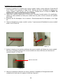
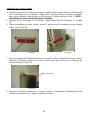
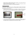
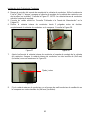
- If necessary, attach two rubber stands (provided) with two (4x8 mm) screws (provided)
to the back of the hood.
- Attach the hood-mounting bracket to the back of the hood with nine (3/16" x 3/8")
screws (provided) as shown in Figure 16.
1. Using references on Table 2 and measurements on Page 22-23, mark the leveling point
of the hood. Position two mounting screws (not provided) on the wall, leaving 1/8” away
from the wall as shown in Figure 17.
Hood Installation
CAUTION: If required to move the cooking range to install the hood, turn off the power on an
electric range at the main electrical box. SHUT OFF THE GAS BEFORE MOVING A GAS
RANGE.
Figure 16 Figure 17
2. Align hood-mounting bracket to the two screws on the wall and hook hood into place.
Tighten screws to secure hood to the wall. CAUTION: MAKE SURE THE HOOD IS
SECURE BEFORE RELEASING.
Mounting
Screws

13
3. Mark the position of the duct cover-mounting bracket. Use reference E from Table 2 and
measurements on Page 22-23. Attach and secure duct cover-mounting bracket with two
screws (not provided). Refer to Figure 18. NOTE: Inner duct cover will cover the duct
cover-mounting bracket.
Duct Cover Installation
4. Use aluminum or steel pipe to connect the plastic exhaust on the hood to the ductwork
above. Use duct tape to make all joints secure and air tight.
5. Connect electrical wires. Refer to “Wiring to Power Supply” on Page 17.
6. Slide the inner duct cover up 2 inches before sliding the entire duct cover onto the hood.
Refer to Figure 19.
Figure 18 Figure 19
7. Adjust the height of the inner duct cover to the duct cover-mounting bracket. Secure the
inner duct cover with two (4x8 mm) screws (provided) as shown in Figure 20.
Figure 20
8. Fasten outer duct cover to multi vent exhaust on the hood with four (4x8 mm) screws
(provided).
Attach Together

14
WALL MOUNT INSTALLATION – REAR VENT
***This installation only applied with the purchase of a duct cover.
- Decide the location of the venting pipe from the hood to the outside. Refer to Figure 21.
Preparation before Installation
NOTE: TO AVOID DAMAGE TO YOUR HOOD, PREVENT DEBRIS FROM ENTERING THE
VENT OPENING.
- A straight, short venting run will allow the hood to perform more efficiently.
- Try to avoid as many transitions, elbows, and long run as possible. This may reduce
the performance of the hood.
- Use duct tape to seal the joints between pipe sections.
- If necessary, prepare back wall frame with cross framing lumber for secure installation.
- Using references on Table 2 and measurements on Page 22-23, decide the level of the
lumber. Refer to Figure 22.
- Temporarily wire the hood to test for proper operation before installing.
Hood Preparation before Installation
- Peel protective film off the hood and the duct cover (if any).
- Remove the screws on the vent cover (rear) and cut along the line of the inner vent
cover (rear) opening. Refer to Figure 23.
- Cut the vent cover (rear) opening and reverse to the other side. Refer to Figure 24.
Figure 21 Figure 22
Inner Vent
Cover (Rear) Reversed
Vent Cover
(Rear)
Figure 23 Figure 24

15
- If necessary, attach two rubber stands (provided) with two (4x8 mm) screws (provided) to
the back of the hood.
- Attach the hood-mounting bracket to the back of the hood with nine (3/16" x 3/8") screws
(provided) as shown in Figure 25.
1. Using references on Table 2 and measurements on Page 22-23, mark the leveling point
of the hood. Position two mounting screws (not provided) on the wall, leaving 1/8” away
from the wall as shown in Figure 26.
Hood Installation
CAUTION: If required to move the cooking range to install the hood, turn OFF the power on an
electric range at the main electrical box. SHUT OFF THE GAS BEFORE MOVING A GAS
RANGE.
Figure 25 Figure 26
2. Use aluminum or steel pipe to connect the exhaust opening at the rear of the hood to the
ductwork. Use duct tape to make all joints secure and air tight.
3. Align hood-mounting bracket to the two screws on the wall and hook hood into place.
Tighten screws to secure hood to the wall. CAUTION: MAKE SURE THE HOOD IS
SECURE BEFORE RELEASING.
Mounting
Screws

16
Duct Cover Installation
4. Mark the position of the duct cover-mounting bracket. Use reference E from Table 2 for
references. Attach and secure duct cover-mounting bracket with two screws (not
provided). Refer to Figure 27. NOTE: Inner duct cover will cover the mounting bracket.
5. Connect electrical wires. Refer to “Wiring to Power Supply” on Page 17.
6. Slide the inner duct cover up 2 inches before sliding the entire duct cover onto the hood.
Refer to Figure 28.
Figure 27 Figure 28
7. Adjust the height of the inner duct cover to the duct cover-mounting bracket. Secure the
inner duct cover with two (4x8 mm) screws (provided) as shown in Figure 29.
Figure 29
8. Fasten outer duct cover to multi vent exhaust on the hood with four (4x8 mm) screws
(provided).
Attach Together

17
Wiring to Power Supply
SAFETY WARNING
RISK OF ELECTRICAL SHOCK. THIS RANGE HOOD MUST BE PROPERLY GROUNDED.
MAKE SURE THIS IS DONE BY SPECIALIZED ELECTRICIAN IN ACCORDANCE WITH ALL
APPLICABLE NATIONAL AND LOCAL ELECTRICAL CODES. BEFORE CONNECTING
WIRES, SWITCH POWER OFF AT SERVICE PANEL AND LOCK SERVICE PANEL TO
PREVENT POWER FROM BEING SWITCHED ON ACCIDENTALLY.
Connect the electrical wires.
- Connect three wires (black, white and green) to house wires and cap with wire
connectors. Connect according to color: black to black, white to white, and green to
green.
- If necessary to hide the electrical wire connections, push wires back into the wiring box.
Access the wire connections underneath the hood. Make sure wires do not slip between
motor or any moving parts to prevent any damage.
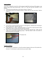
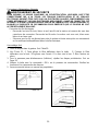
Final Assembly
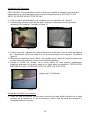
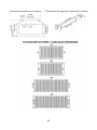
1. Attach oil tunnel. Refer to Figure 30.
2. Refer to Figure 31. Slide the baffle filter into the hood. Push the baffle filter upward.
Slide forward. Pull downward. Fit into place.
3. For bottom casing, repeat above steps. Refer to Page 23.
4. Turn power ON in control panel. Check all lights and fan operation.
5. Make sure to leave this manual for the homeowner.
Figure 30
Figure 31

18
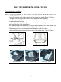
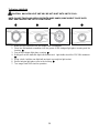
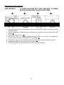
OPERATING INSTRUCTIONS
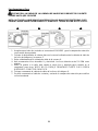
This KOBE hood is equipped with four electronic controls with a 10-second standby startup &
30-second delay shutoff, two powerful centrifugal turbine impellers with baffle filters, and bright
12-volt 20-watt halogen lights.
The four electronic controls are Light Control, Speed Control A, Speed Control B and the Power Control
(On/Off). Refer to Figure 32.
Figure 32
TURN ON:
• Press Power Control (On/Off) button once.
(Note: If any control button is not pressed within 10 seconds, power will be automatically
turned off).
• The hood will start on Low speed. Each press of the Speed Control button will cycle
through the various speeds.
• Press Speed Control A button to cycle from Low, Medium, High, or QuietMode.
Press Speed Control B button to cycle from Low, QuietMode
, High or Medium.
(Note: Speed Control A or B will operate both fans. These two speed buttons vary the
speed quicker.)
• Press Light Control button to turn halogen light on.
TURN OFF:
• Press Power Control (On/Off) button once, panel lights will flash and power will be
completely shut off after 30 seconds.
OR
• Press Power Control (On/Off) button twice, all power will be shut off immediately.
• If only the lights are on, pressing Power Control (On/Off) button once will turn power
off after 30 seconds.
La page est en cours de chargement...
La page est en cours de chargement...
La page est en cours de chargement...
La page est en cours de chargement...
La page est en cours de chargement...
La page est en cours de chargement...
La page est en cours de chargement...
La page est en cours de chargement...
La page est en cours de chargement...
La page est en cours de chargement...
La page est en cours de chargement...
La page est en cours de chargement...
La page est en cours de chargement...
La page est en cours de chargement...
La page est en cours de chargement...
La page est en cours de chargement...
La page est en cours de chargement...
La page est en cours de chargement...
La page est en cours de chargement...
La page est en cours de chargement...
La page est en cours de chargement...
La page est en cours de chargement...
La page est en cours de chargement...
La page est en cours de chargement...
La page est en cours de chargement...
La page est en cours de chargement...
La page est en cours de chargement...
La page est en cours de chargement...
La page est en cours de chargement...
La page est en cours de chargement...
La page est en cours de chargement...
La page est en cours de chargement...
La page est en cours de chargement...
La page est en cours de chargement...
La page est en cours de chargement...
La page est en cours de chargement...
La page est en cours de chargement...
La page est en cours de chargement...
La page est en cours de chargement...
La page est en cours de chargement...
La page est en cours de chargement...
La page est en cours de chargement...
La page est en cours de chargement...
La page est en cours de chargement...
La page est en cours de chargement...
La page est en cours de chargement...
La page est en cours de chargement...
La page est en cours de chargement...
La page est en cours de chargement...
La page est en cours de chargement...
La page est en cours de chargement...
La page est en cours de chargement...
La page est en cours de chargement...
La page est en cours de chargement...
La page est en cours de chargement...
La page est en cours de chargement...
La page est en cours de chargement...
La page est en cours de chargement...
La page est en cours de chargement...
La page est en cours de chargement...
La page est en cours de chargement...
La page est en cours de chargement...
La page est en cours de chargement...
La page est en cours de chargement...
La page est en cours de chargement...
La page est en cours de chargement...
La page est en cours de chargement...
La page est en cours de chargement...
La page est en cours de chargement...
La page est en cours de chargement...
La page est en cours de chargement...
La page est en cours de chargement...
La page est en cours de chargement...
La page est en cours de chargement...
La page est en cours de chargement...
La page est en cours de chargement...
La page est en cours de chargement...
La page est en cours de chargement...
La page est en cours de chargement...
La page est en cours de chargement...
La page est en cours de chargement...
La page est en cours de chargement...
-
 1
1
-
 2
2
-
 3
3
-
 4
4
-
 5
5
-
 6
6
-
 7
7
-
 8
8
-
 9
9
-
 10
10
-
 11
11
-
 12
12
-
 13
13
-
 14
14
-
 15
15
-
 16
16
-
 17
17
-
 18
18
-
 19
19
-
 20
20
-
 21
21
-
 22
22
-
 23
23
-
 24
24
-
 25
25
-
 26
26
-
 27
27
-
 28
28
-
 29
29
-
 30
30
-
 31
31
-
 32
32
-
 33
33
-
 34
34
-
 35
35
-
 36
36
-
 37
37
-
 38
38
-
 39
39
-
 40
40
-
 41
41
-
 42
42
-
 43
43
-
 44
44
-
 45
45
-
 46
46
-
 47
47
-
 48
48
-
 49
49
-
 50
50
-
 51
51
-
 52
52
-
 53
53
-
 54
54
-
 55
55
-
 56
56
-
 57
57
-
 58
58
-
 59
59
-
 60
60
-
 61
61
-
 62
62
-
 63
63
-
 64
64
-
 65
65
-
 66
66
-
 67
67
-
 68
68
-
 69
69
-
 70
70
-
 71
71
-
 72
72
-
 73
73
-
 74
74
-
 75
75
-
 76
76
-
 77
77
-
 78
78
-
 79
79
-
 80
80
-
 81
81
-
 82
82
-
 83
83
-
 84
84
-
 85
85
-
 86
86
-
 87
87
-
 88
88
-
 89
89
-
 90
90
-
 91
91
-
 92
92
-
 93
93
-
 94
94
-
 95
95
-
 96
96
-
 97
97
-
 98
98
-
 99
99
-
 100
100
-
 101
101
-
 102
102


Kobe Range Hoods CH7930SQB Manuel utilisateur
- Catégorie
- Hottes
- Taper
- Manuel utilisateur
- Ce manuel convient également à