Maytag MHN33PDCWW Guide d'installation
- Catégorie
- Machines à laver
- Taper
- Guide d'installation

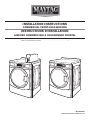
INSTALLATION INSTRUCTIONS
COMMERCIAL FRONT-LOAD WASHER
INSTRUCTIONS D’INSTALLATION
LAVEUSE COMMERCIALE À CHARGEMENT FRONTAL
Table of Contents/Table des matières . . . . . . . . . . . . . . . . . . . . . . . . . . . . . . . . . . . . . . . . 2
W11033207C
www.maytagcommerciallaundry.com

2
TABLE OF CONTENTS
WASHER SAFETY ................................................................................... 3
INSTALLATION REQUIREMENTS ..........................................................4
Tools and Parts .....................................................................................4
Accessories .......................................................................................... 4
Options .................................................................................................4
Location Requirements ........................................................................5
Drain System ........................................................................................ 5
Electrical Requirements........................................................................6
INSTALLATION INSTRUCTIONS ............................................................6
Remove Transport System ................................................................... 6
Connect the Inlet Hoses .......................................................................7
Connect the Drain Hose ....................................................................... 8
Secure the Drain Hose .........................................................................8
Level the Washer .................................................................................. 9
Complete Installation............................................................................9
USER & SET-UP INSTRUCTIONS ........................................................ 10
General User Information ...................................................................10
Control Set-up Procedures ................................................................10
Start Operating Set-up ....................................................................... 10
WASHER CARE .....................................................................................14
Cleaning Your Washer ........................................................................14
Water Inlet Hoses ............................................................................... 15
ASSISTANCE OR SERVICE .................................................................. 15
WARRANTY ........................................................................................... 16
TABLE DES MATIÈRES
SÉCURITÉ DE LA LAVEUSE ................................................................17
EXIGENCES D’INSTALLATION ............................................................18
Outillage et pièces ..............................................................................18
Accessoires ........................................................................................18
Options ...............................................................................................19
Exigences d’emplacement ................................................................. 19
Système de vidange ...........................................................................20
Spécications électriques ..................................................................20
INSTRUCTIONS D’INSTALLATION ...................................................... 21
Dépose du système de transport ....................................................... 21
Raccordement des tuyaux d’alimentation..........................................22
Raccordement du tuyau de vidange ..................................................23
Immobilisation du tuyau de vidange ..................................................23
Réglage de l’aplomb de la laveuse ....................................................24
Achever l’installation ..........................................................................24
INSTRUCTIONS D’UTILISATION ET D’INSTALLATION .....................25
Informations générales ....................................................................... 25
Procédures de réglage des systèmes de commande ........................ 25
Paramétrage pour mise en marche .................................................... 26
ENTRETIEN DE LA LAVEUSE ..............................................................30
Nettoyage de la laveuse .................................................................... 30
Tuyaux d’arrivée d’eau .......................................................................31
ASSISTANCE OU SERVICE .................................................................. 31
GARANTIE ............................................................................................. 32

3
WASHER SAFETY

4
Alternate Parts
Your installation may require additional parts. If you are interested
in purchasing one of the items listed here, call the toll-free number
in the “Assistance or Service” section.
If you have You will need to buy
Laundry tub or standpipe
taller than 96" (2.4 m)
Sump pump system (if not already
available)
Overhead sewer Standard 20 gal. (76 L), 30" (762 mm)
tall drain tub or utility sink and sump
pump (available from local plumbing
suppliers)
Floor drain Siphon break, Part Number 285834;
additional drain hose,
Part Number 8318155; and connector
kit, Part Number 285835
Drain hose too short 4 ft. (1.2 m) drain hose extension kit,
Part Number 285863
W
ater faucets beyond
reach of ll hoses
2 longer water ll hoses:
6 ft. (1.8 m) Part Number 76314
10 ft. (3.0 m) Part Number 350008
Accessories
Enhance your washer with these premium accessories.
For more high-quality items or to order, call 1-800-901-2042,
or visit us at www.maytag.com/accessories. In Canada call:
1-800-807-6777
or visit us at www.whirlpoolparts.ca.
Part Number Accessory
8212526
Washer drip trays, ts under all
31682
All purpose appliance cleaner
1903WH
Laundry supply storage cart
Options
Pedestal
You have the option of purchasing pedestals separately for this
washer. The pedestal will add to the total height of the washer.
Optional pedestal
Pedestal
Height
Approximate
height with washer
Color
Part Number
2
7
⁄8" (73 mm) 47.5" (1207 mm) White WHP0400VW
NOTE: Some models have pedestal pre-installed.
INSTALLATION REQUIREMENTS
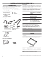
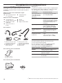
Tools and Parts
Gather the required tools and parts before starting installation.
The parts supplied are in the washer drum.
Tools needed for connecting the water inlet hoses:
■ Pliers (that open to
1
9
⁄16" [39.5 mm])
■ Flashlight (optional)
Tools needed for installation:
■ Open end wrenches
1/2" (13 mm) and 9/16"
(14 mm)
■ TORX T20
®†
security
screwdriver
■ 1/4" (6 mm) Nut driver
■ Level
■ Wood block
■ Ruler or measuring tape
A. U-shaped hose form
B. Water inlet hoses (2)
C. Inlet hose washers (4)
D. Transit bolt hole plug (4)
E. Beaded tie strap
F. Drain hose
G. Hose clamp
Parts supplied:
AB
F
G
C
DE
†
®
TORX and T20 are registered trademarks of Acument Intellectual Properties, LLC.
Parts supplied for PD Models:
Service door lock cam
Parts supplied for PR Models:
Card reader bezel Screws (2)

5
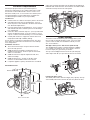
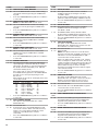
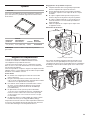
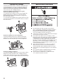
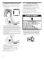
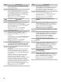
Washer Dimensions
A oor drain should be provided under the bulkhead. Prefabricated
bulkheads with electrical outlets, water inlet lines, and drain facilities
should be used only where local codes permit.
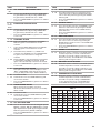
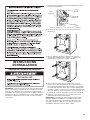
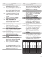
Drain System
The washer can be installed using the standpipe drain system
(oor or wall), the laundry tub drain system, or the oor drain
system. Select the drain hose installation method you need.
See “Tools and Parts.”
Standpipe drain system – wall or oor (views A & B)
The standpipe drain requires a minimum diameter standpipe
of 2" (50 mm). The minimum carry-away capacity can be no
less than 10 gal. (38 L) per minute, per washer.
The top of the standpipe must be at least 30" (762 mm) high
and no higher than 96" (2.4 m) from the bottom of the washer.
30" min.
(762 mm)
Laundry tub drain system
The laundry tub needs a minimum 20 gal. (76 L) capacity. The top
of the laundry tub must be at least 30" (762 mm) above the oor.
Location Requirements
Selecting the proper location for your washer improves
performance and minimizes noise and possible washer “walk.”
Your washer can be installed under a custom counter, or in a
basement, laundry room, or recessed area. See “Drain System.”
Companion appliance location requirements should also be
considered. Proper installation is your responsibility.
You will need
■ A water heater set to deliver 120°F (49°C) water to the washer.
■ A grounded electrical outlet located within 6 ft. (1.8 m) of
where the power cord is attached to the back of the washer.
See “Electrical Requirements.”
■ Hot and cold water taps located within 4 ft. (1.2 m) of the hot
and cold water ll valves, and water pressure of 20–100 psi
(137.9–689.6 kPa).
■ A level oor with a maximum slope of 1" (25 mm) under entire
washer. Installing the washer on soft oor surfaces, such as
carpets or surfaces with foam backing, is not recommended.
■ A sturdy and solid oor to support the washer with a total
weight (water and load) of 400 lbs (180 kg).
Do not operate your washer in temperatures below 32°F (0°C).
Some water can remain in the washer and can cause damage
in low temperatures.
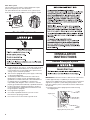
Installation clearances
■ The location must be large enough to allow the washer
door to be fully opened.
■ Additional spacing should be considered for ease of
installation and servicing. The door opens more than 90°,
and it is not reversible.
■ Additional clearances might be required for wall, door,
and oor moldings.
■ Additional spacing of 1" (25 mm) on all sides of the
washer is recommended to reduce noise transfer.
■ Companion appliance spacing should also be considered.
A B
Door is not reversible
30" min.
(762 mm)
28" min.
(710 mm)
50
1
/2"
(1282 mm)
37
13
/16"
(961 mm)
27"
(686 mm)
28
13
/16"
(732 mm)
44
5
/8"
(1134 mm)

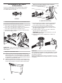
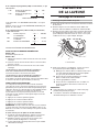
6
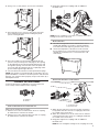
Shipping bolt with plastic spacer
INSTALLATION
INSTRUCTIONS
Remove Transport System
IMPORTANT: Position the washer so that the rear of the washer
is within approximately 3 ft. (900 mm) of its nal location.
There are four shipping bolts in the rear panel of the washer that
support the suspension system during transportation. These
bolts also retain the power cord inside the washer until the bolts
are removed.
1. Keep the washer in the upright position while removing
the shipping bolts.
Shipping bolt
Shipping bolt
Electrical Requirements
■ A 120-volt, 60 Hz., AC-only, 15- or 20-amp, fused electrical
supply is required. A time-delay fuse or circuit breaker is
recommended. It is recommended that a separate circuit
serving only this washer be provided.
■ This washer is equipped with a power supply cord having
a 3 prong grounding plug.
■ To minimize possible shock hazard, the cord must be
plugged into a mating, 3 prong, grounding-type outlet,
grounded in accordance with local codes and ordinances.
If a mating outlet is not available, it is the personal
responsibility and obligation of the customer to have the
properly grounded outlet installed by a qualied electrician.
■ If codes permit and a separate ground wire is used, it is
recommended that a qualied electrician determine that
the ground path is adequate.
■ Do not ground to a gas pipe.
■ Check with a qualied electrician if you are not sure
if the washer is properly grounded.
■ Do not have a fuse in the neutral or ground circuit.
Floor drain system
The oor drain system requires a siphon break that may be
purchased separately. See “Tools and Parts.”
The siphon break must be a minimum of 28" (710 mm) from
the bottom of the washer. Additional hoses might be needed.
30" min.
(762 mm)
28" min.
(710 mm)

7
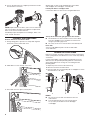
2. Using a 1/2" (13 mm) wrench, loosen each of the bolts.
3. Once the bolt is loose, move it to the center of the hole
and completely pull out the bolt, including the plastic
spacer covering the bolt.
4. Once all four bolts are removed, discard the bolts and
spacers. Then push the power cord plug into the opening
on the right side of the rear panel and pull the power cord
through the opening on the left side of the rear panel and
close holes with the attached cap. Do not pull plug end of
power cord through the right side hole.
5. Close the bolt holes with the four transport bolt hole plugs.
NOTE: If the washer is to be transported at a later date, call your
product distributor or installer. To avoid suspension and structural
damage, your washer must be properly set up for relocation by a
trained professional.
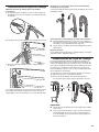
Connect the Inlet Hoses
Insert new at washers (supplied) into each end of the inlet
hoses. Firmly seat the washers in the couplings.
A B
A. Coupling
B. Washer
Connect the inlet hoses to water faucets
Make sure the washer drum is empty.
1. Attach a hose to the hot water faucet. Screw on coupling
by hand until it is seated on the washer.
2. Attach a hose to the cold water faucet. Screw on coupling
by hand until it is seated on the washer.
3. Using pliers, tighten the couplings with an additional
two-thirds turn.
NOTE: Do not overtighten or use tape or sealants on the valve.
Damage to the valves can result.
Clear water lines
■ Run water through both faucets and inlet hoses, into a
laundry tub, drainpipe, or bucket, to get rid of particles
in the water lines that might clog the inlet valve screens.
■ Check the temperature of the water to make sure that
the hot water hose is connected to the hot water faucet
and that the cold water hose is connected to the cold
water faucet.
Connect the inlet hoses to the washer
C. Cold water inlet
H. Hot water inlet
1. Attach the hot water hose to the check valve on washer’s
hot (H) water inlet valve. Screw on coupling by hand until
it is seated on the check valve.
2. Attach the cold water hose to the check valve on washer’s
cold (C) water inlet valve. Screw on coupling by hand until
it is seated on the check valve.
3. Using pliers, tighten the couplings with an additional
two-thirds turn.
NOTE: Do not overtighten. Damage to the coupling can result.

8
4. Turn on the water faucets completely and check for leaks
and at washer connection.
NOTE: Replace inlet hoses after 5 years of use to reduce the
risk of hose failure. Record hose installation or replacement
dates on the hoses for future reference.
Periodically inspect and replace hoses if bulges, kinks, cuts,
wear, or leaks are found.
Connect the Drain Hose
Remove drain hose from washer drum
1. Using locking pliers, squeeze hose clamp tabs together
and insert over the end of drain hose.
2. Slide drain hose onto washer connection.
3. Once drain hose is in place, release pliers.
Washer drain system can be installed using a oor drain,
wall standpipe, oor standpipe, or laundry tub.
Laundry tub drain or standpipe drain
Connect the drain hose form to the corrugated drain hose.
To keep drain water from going back into the washer:
■ Use the drain hose form, and do not force excess drain
hose into standpipe. Hose should be secure but loose
enough to provide a gap for air.
■ Do not lay excess hose on the bottom of the laundry tub.
Floor drain
You may need additional parts. See Floor drain under
“Tools and Parts.”
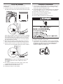
Secure the Drain Hose
Drain hose must be secured to stop the hose from moving when
water is pumped out. If the drain hose moves, water may end up
on the oor.
It is the responsibility of the installer to install and secure the
drain hose into the provided plumbing/drain in a manner that
will avoid the drain hose coming out of or leaking from the
plumbing/drain.
1. Drape the power cord over the washer top.
2. Move the washer to its nal location.
3. Place the drain hose in the laundry tub or standpipe as shown.
See illustrations A, B, and C.
A B C
NOTES:
■ Do not force excess drain hose back into the rear
of the washer.
■ To avoid siphoning, do not seal or put more than
4½" (114 mm) of the drain hose into drainpipe
or standpipe.
4
1
/2"
(114 mm)
4
1
/2"
(114 mm)
4
1
/2"
(114 mm)

9
Level the Washer
Properly leveling your washer avoids excessive noise
and vibration.
1. Check the levelness of the washer by placing a level on the
top edge of the washer, rst side-to-side, then front to back.
Jam nut
If the washer is against a wall, move the washer out slightly
before tipping back. If the washer is not level, rst prop the
front with a wood block and adjust the feet as necessary;
then, prop the back and adjust feet as necessary. Repeat
this step until washer is level.
2. Make sure all four feet are stable and resting on the oor.
Then check that the washer is perfectly level (use a level).
3. After the washer is level, use a 9/16" open-end wrench to
turn the nuts on the feet tightly against the washer cabinet.
Jam nut
IMPORTANT: All four feet must be tightened. If the nuts
are not tight against the washer cabinet, the washer
may vibrate.
4. The washer should not move front to back, side to side,
or diagonally when pushed on its top edges.
5. Slide the washer to its nal location.
6. Conrm the levelness of the washer.
Complete Installation
1. Check the electrical requirements. Be sure that you have the
correct electrical supply and the recommended grounding
method. See “Electrical Requirements.”
2. Check that all parts are now installed. If there is an extra part,
go back through the steps to see which step was skipped.
3. Check that you have all of your tools.
4. Dispose of/recycle all packaging materials.
5. Check that the water faucets are on.
6. Check for leaks around faucets and inlet hoses.
7. Plug into a grounded 3 prong outlet.
8. To test and to clean your washer, measure 1/2 the detergent
manufacturer’s recommended amount of High Efciency (HE)
detergent for a medium-size load. Pour the detergent into
the detergent dispenser. Select any cycle and allow the
washer to complete one whole cycle.

10
NOTE: After the washer has been installed and plugged in,
the display may show ‘0 MINUTES’. Once the washer has been
plugged in and the washer door opened and closed, the display
will show the price. In washers set for free cycles, the display will
ash ‘SELECT CYCLE’.
1. PD Models: Insert coins until ‘SELECT CYCLE’ ashes
in display.
PR Models: A debit card is required rather than coins. In
Enhanced Debit mode, the card balance will also display
when a debit card is inserted into the reader.
2. Door must be closed before cycle selection is made,
3. Press fabric setting key pad for the wash cycle desired. After
the cycle is started, the time will display and count down.
4. If a cycle is interrupted by opening the door, ‘RESELECT
CYCLE’ will ash in the display. To restart the washer,
close door, and reselect desired cycle.
General User Information
SCROLLING ‘OUT OF ORDER’ SHOWING IN DISPLAY
This condition indicates the washer is inoperative.
‘0 MINUTES’ SHOWING IN DISPLAY
This indicates the cycle is complete and the washer cannot be
operated. Coins dropped or debit inputs during this condition will
be stor
ed in escr
ow but cannot be used until normal operation
is restored by opening and closing the door. If a door switch fails,
it must be replaced before normal operation can be restored.
COLD ST
ART (Initial rst use)
Washer is programmed at the factory as follows:
11-minute wash period
3 rinses (extra rinse not enabled)
$1.75 wash price (PD models)
$0 00 wash price (PR models)
WARM STAR
T (after power failure)
A few seconds after power is restored, if a cycle was in progress
at the time of the power failure, ‘RESELECT CYCLE’ will ash
in the display, indicating the need for a key press to restart the
washer
.
DOOR LOCK
Prior to beginning a cycle, there is a door lock r
outine of lock/
unlock/r
elock; then cycle begins. The door will remain locked
until the end of a cycle or appr
oximately 2 minutes after a power
interruption.
PRICING
After the door is opened following the completion of a cycle,
the display indicates the cycle price (unless set for free operation).
As coins ar
e dropped or debit inputs arrive, the display will change
to lead the user thr
ough the initiation of a cycle.
FREE CYCLES
This is established by setting the cycle price to zero. When this
happens, ‘SELECT CYCLE’ will appear rather than a cycle price.
DEBIT CARD READY
This washer is debit card ‘cable’ ready. It will accept a variety of
debit car
d systems, but does NOT come with a debit card reader.
Refer to the debit card reader manufacturer for proper washer
set-up. In models converted to a Generation 1 debit card system,
debit pulses represent the equivalent of one coin (coin 1).
Control Set-up Procedures
IMPORTANT: Read all instructions before operating.
PD Models: Insert access door key, turn, and lift to remove
access door.
PR Models:
Once the debit card r
eader is installed (according
to the reader manufacturer’s instructions), the set-up mode can
only be entered by inserting a set-up card (supplied by the reader
manufacturer) into the card slot. If a set-up card is not available,
diagnostic modes can be entered by removing connector AA1 on
the circuit board or by using the Service Access Code (see Service
Access Code section, page 14) for PR models set up as a PN.
The lower fabric setting key pads and the digital display are used
to set up the controls.
The display can contain four numbers and/or letters and a
decimal point. These are used to indicate the set-up codes and
related code values available for use in programming the washer.
HOW TO USE THE KEY PADS TO PROGRAM THE CONTROLS
1. POWERWASH – UPPER LEFT key pad is used to adjust
the values associated with set-up codes. Pressing the key pad
will increment the value. Rapid adjustment is possible by
holding the key pad down.
2. The TEMPERATURE – LOWER LEFT key pad is used to adjust
the values associated with set-up codes. Pressing the key pad
will decrement the value. Rapid adjustment is possible by
holding down the key pad.
3. The EXTRA RINSE – LOWER MIDDLE key pad will advance
through the set-up codes. Pressing the key pad will advance
to the next available set-up code. Holding the key pad down
will automatically advance through the set-up codes at a rate
of 1 per second.
4. The DELICATES – UPPER RIGHT key pad is used to select or
deselect options.
Start Operating Set-up
Before proceeding, it is worth noting that, despite all of the
options available, an owner can simply choose to uncrate a new
commercial washer, hook it up, plug it in, and have a washer
that operates.
Washers are preset at the factory for an 11-minute wash period
and three rinses (no extra rinse).
SET-UP CODES
■ The
EXTRA RINSE – LOWER MIDDLE
key pad will advance
you from code to code.
■ The
TEMPERATURE – LOWER LEFT and POWERWASH –
UPPER LEFT
key pads will change the code value.
■ The
DELICATES – UPPER RIGHT
key pad will select or
deselect options.
FOR PR MODELS: The set-up codes are the same as for the
“PD” model except where noted.
The set-up code is indicated by the one or two left-hand
characters. The set-up code value is indicated by the two
or three right-hand characters.
USER & SET-UP INSTRUCTIONS

11
CODE EXPLANATION
6 07 NORMAL REGULAR CYCLE PRICE
NORMAL (Factory Default)
6
6
07
00
g
Represents the number of quarters (coin 1); may
adjust from 0–200. (See VALUE OF COIN 1.) Increase
from 0–200 by pressing the
UPPER LEFT
key pad
and decrease by pressing LOWER LEFT key pad.
Factory default of 7 quarters = $1.75.
PR MODELS ONLY: Factory default of 0 quarters.
6 01 setting would represent one coin slide actuation.
Press the
LOWER MIDDLE
key pad once to advance
to next code.
6 07 DELICATES REGULAR CYCLE PRICE
DELICATES (Factory Default)
6
6
07
00
g
Represents the number of quarters (coin 1); may
adjust from 0–200. (See VALUE OF COIN 1.) Increase
from 0–200 by pressing the
UPPER LEFT
key pad
and decrease by pressing LOWER LEFT key pad.
Factory default of 7 quarters = $1.75.
PR MODELS ONLY: Factory default of 0 quarters.
6 01 setting would represent one coin slide actuation.
Press the
LOWER MIDDLE
key pad once to advance
to next code.
6 07
POWERWASH REGULAR CYCLE PRICE
POWER
(Factory Default)
WASH
6
6
07
00
g
Represents the number of quarters (coin 1); may
adjust from 0–200. (See VALUE OF COIN 1.) Increase
from 0–200 by pressing the
UPPER LEFT
key pad
and decrease by pressing LOWER LEFT key pad.
Factory default of 7 quarters = $1.75.
PR MODELS ONLY: Factory default of 0 quarters.
6 01 setting would represent one coin slide actuation.
Press the
LOWER MIDDLE
key pad once to advance
to next code.
7 11 WASH LENGTH
7 11
g
This is the number of minutes for WASH. Washer comes
from the factory preset with 11 minutes. Choose from
9–17 minutes by pressing the
LOWER LEFT
key pad.
Press the
LOWER MIDDLE
key pad once to advance
to next code.
8 00 ADDITIONAL RINSE OPTION/EXIT SERVICE MODE
8
8
00
Ar
g
NOTE: This only affects NORMAL and DELICATES
cycles. Additional Rinse is always enabled for
POWERWASH.
Additional Rinse not selected ‘OFF’.
Use this eld to exit Service Mode when entered
via the key dance.
Press and hold the LOWER LEFT key pad to exit
Service Mode.
Additional Rinse selected ‘ON’.
Use this eld to exit Service Mode when entered
via the key dance.
Press and hold the LOWER LEFT key pad to exit
Service Mode.
Press the LOWER MIDDLE key pad once to advance
to next code.
9 00 CYCLE COUNTER OPTION
This option is either SELECTED ‘ON’ or NOT
SELECTED ‘OFF’.
9
9
00
0C
g
Not Selected ‘OFF’.
Selected ‘ON’ and not able to be deselected.
Press the LOWER RIGHT key pad 3 consecutive
times to select ‘ON’. Once selected ‘ON’ it cannot
be deselected.
Press the
LOWER MIDDLE
key pad once to advance
to next code.
CODE EXPLANATION
1. 00 MONEY COUNTER OPTION
This option is either SELECTED ‘ON’ or NOT
SELECTED ‘OFF’.
1.
1.
1
00
0C
C0
g
Not Selected ‘OFF’.
Selected ‘ON’.
Press the UPPER RIGHT key pad 3 consecutive
times to select ‘ON’ and 3 consecutive times to
remove (Not Selected ‘OFF’.) Counter resets by
going from ‘OFF’ to ‘ON’.
Selected ‘ON’ and not able to be deselected.
To select ‘ON’ and not able to be deselected,
rst select ‘ON’, then within 2 seconds, press
the LOWER RIGHT key pad twice,
LOWER LEFT key
pad
once, and exit the set-up mode.
Press the
LOWER MIDDLE
key pad
once to advance
to next code.
2. 00 SPECIAL PRICING OPTIONS
This option is either SELECTED ‘ON’ or NOT
SELECTED ‘OFF’.
2.
2.
00
SP
Not Selected ‘OFF’, and next available code will be
A.00.
Selected ‘ON’. Press the UPPER RIGHT key pad
once for this selection.
NOTE: If SPECIAL PRICING OPTION is selected, there is
access to codes ‘3.XX’ through ‘9.XX’.
g
Press the
LOWER MIDDLE
key pad once to advance
to next code.
Options to use if SPECIAL PRICING is selected:
3. 07 NORMAL SPECIAL CYCLE PRICE
NORMAL
3.
3.
07
00
g
Represents the number of quarters (coin 1);
may adjust from 0–200. (See VALUE OF COIN 1.)
Increase from 0–200 by pressing the
UPPER LEFT
key pad and decrease by pressing LOWER LEFT key
pad. Factory default of 7 quarters = $1.75.
PR MODELS ONLY: Factory default of 0 quarters.
Press the
LOWER MIDDLE
key pad once to advance
to next code.
3. 07 DELICATES SPECIAL CYCLE PRICE
DELICATES
3.
3.
07
00
g
Represents the number of quarters (coin 1);
may adjust from 0–200. (See VALUE OF COIN 1.)
Increase from 0–200 by pressing the
UPPER LEFT
key pad and decrease by pressing LOWER LEFT key
pad. Factory default of 7 quarters = $1.75.
PR MODELS ONLY: Factory default of 0 quarters.
Press the
LOWER MIDDLE
key pad once to advance
to next code.
3. 07
POWERWASH SPECIAL CYCLE PRICE
POWERWASH
3.
3.
07
00
g
Represents the number of quarters (coin 1);
may adjust from 0–200. (See VALUE OF COIN 1.)
Increase from 0–200 by pressing the
UPPER LEFT
key pad and decrease by pressing LOWER LEFT key
pad. Factory default of 7 quarters = $1.75.
PR MODELS ONLY: Factory default of 0 quarters.
Press the
LOWER MIDDLE
key pad once to advance
to next code.

12
CODE EXPLANATION
5. 00 TIME-OF-DAY CLOCK, MINUTES
5. 00
g
This is the TIME-OF-DAY CLOCK, minute setting;
select 0–59 minutes by pressing the
LOWER LEFT
key pad.
Press the
LOWER MIDDLE
key pad once to advance
to next code.
6. 00 TIME-OF-DAY CLOCK, HOURS
NOTE: Uses MILITARY TIME or 24 hr. clock.
6. 00
g
This is the TIME-OF-DAY CLOCK, hour setting;
select 0–23 hours by pressing the
LOWER LEFT
key pad.
Press the
LOWER MIDDLE
key pad once to advance
to next code.
7. 00 SPECIAL PRICE START HOUR
NOTE: Uses MILITARY TIME or 24 hr. clock.
7. 00
g
This is the start hour; 0–23 hours. Select START
HOUR by pressing the
LOWER LEFT or UPPER
LEFT
key pad.
Press the
LOWER MIDDLE
key pad once to advance
to next code.
8. 00 SPECIAL PRICE STOP HOUR
NOTE: Uses MILITARY TIME or 24 hr. clock.
8. 00
g
This is the stop hour; 0–23 hours. Select STOP
HOUR by pressing the
LOWER LEFT
or UPPER
LEFT
key pad.
Press the
LOWER MIDDLE
key pad once to advance
to next code.
9. 10 SPECIAL PRICE DAY
9. 10
g
This represents the day of the week and whether
special pricing is selected for that day. A number
followed by ‘0’ indicates no selection that particular
day (9.10). A number followed by an ‘S’ indicates
selected for that day (9.1S).
Days of the week (1–7) are selected by pressing
the
LOWER LEFT
key pad. Press the UPPER RIGHT
key pad once to select special pricing for each
day chosen.
When exiting set-up code ‘9’, the display must show
current day of week:
DISPLAY DAY OF WEEK CODE (selected)
10 Day 1 = Sunday 1S
20 Day 2 = Monday 2S
30 Day 3 = Tuesday 3S
40 Day 4 = Wednesday 4S
50 Day 5 = Thursday 5S
60 Day 6 = Friday 6S
70 Day 7 = Saturday 7S
Press the
LOWER MIDDLE
key pad once to advance
to next code.
A. 00 VAULT VIEWING OPTION
This option is either SELECTED ‘ON’ or NOT
SELECTED ‘OFF’.
A.
A.
00
SC
g
Not Selected ‘OFF’.
Selected ‘ON’. Press the UPPER RIGHT key pad
once for this selection. When selected, the money
and/or cycle counts will be viewable (if counter
option(s) is selected) when the coin box
is removed.
Press the
LOWER MIDDLE
key pad once to advance
to next code.
CODE EXPLANATION
b. 05 VALUE OF COIN 1
b. 05
g
This represents the value of coin 1 in number
of $0.05 increments of the larger coin value.
5 x $0.05 = $0.25.
By pressing the
LOWER LEFT
key pad, there is the
option of 1–199 for the quantity of $0.05 increments.
Press the
LOWER MIDDLE
key pad once to advance
to next code.
C. 20 VALUE OF COIN 2
C.
C.
20
05
g
This represents the value of coin 2 in number
of $0.05 increments of the larger coin value.
20 x $0.05 = $1.00.
PR MODELS ONLY: Factory default of $0.25.
By pressing the
LOWER LEFT
key pad, there is the
option of 1–199 for the quantity of $0.05 increments.
Press the
LOWER MIDDLE
key pad once to advance
to next code.
d. 00 COIN SLIDE OPTION
This option is either SELECTED ‘ON’ or NOT
SELECTED ‘OFF’. Replacement of meter case will
be needed for coin slide mounting.
d.
d.
00
CS
g
Not Selected ‘OFF’.
Selected ‘ON’.
NOTE: This option needs to be set to ‘00’ unless
the meter case has been changed to accept a coin
slide device. Press the
UPPER RIGHT
key pad 3
consecutive times for this selection.
When coin slide mode is selected, set ‘b’. equal to
value of vend price in $0.05 increments. Set set-up
code 6 xx (regular cycle price) and set-up code 3.xx
(special cycle price) to number of slide operations.
If the installer sets-up ‘CS’ and a coin drop
mechanism is installed, the washer will not register
coins that are inserted.
Press the
LOWER MIDDLE
key pad once to advance
to next code.
E. 00 ADD COINS OPTION
This option is either SELECTED ‘ON’ or NOT
SELECTED ‘OFF’. This option causes the customer
display to show the number of coins (coin 1) to
enter, rather than the dollars-and-cents amount.
E.
E.
00
AC
g
Not Selected ‘OFF’.
Selected ‘ON’. Press the
UPPER RIGHT
key pad 3
consecutive times for this selection.
Press the
LOWER MIDDLE
key pad once to advance
to next code.
H. 00 COOL TEMPERATURE UPGRADE PRICE
COOL
H. 00
g
Increase from 0–200 by pressing the
UPPER LEFT
key pad and decrease by pressing LOWER LEFT
key pad. Factory default for 0 coins = $0.00.
Press the LOWER MIDDLE key pad once to advance
to next code.
H. 00 WARM TEMPERATURE UPGRADE PRICE
WARM
H. 00
g
Increase from 0–200 by pressing the
UPPER LEFT
key pad and decrease by pressing LOWER LEFT
key pad. Factory default for 0 coins = $0.00.
Press the LOWER MIDDLE key pad once to advance
to next code.

13
CODE EXPLANATION
H. 00 HOT TEMPERATURE UPGRADE PRICE
HOT
H. 00
g
Increase from 0–200 by pressing the
UPPER LEFT
key pad and decrease by pressing LOWER LEFT
key pad. Factory default for 0 coins = $0.00.
Press the LOWER MIDDLE key pad once to advance
to next code.
H. 01 EXTRA RINSE UPGRADE PRICE
EXTRA
RINSE
H. 01
g
Increase from 0–200 by pressing the
UPPER LEFT
key pad and decrease by pressing LOWER LEFT
key pad. Factory default for 0 coins = $0.00.
Press the LOWER MIDDLE key pad once to advance
to next code.
J. Cd COIN/DEBIT OPTION
J.
J.
J.
J.
Cd
C_
_d
Ed
g
Both coin and debit selected. Press the
UPPER
RIGHT
key pad 3 consecutive times for this
selection.
Coins selected, debit disabled. Press the
UPPER
RIGHT
key pad 3 consecutive times for this
selection.
PR models factory default to J._d. Debit Card
selected, coins disabled. Press the UPPER RIGHT
key pad 3 consecutive times to change this
selection.
Enhanced Debit is self-selected when a Generation
2 card reader is installed in the washer. The Ed
option cannot be manually selected or deselected.
Press the
LOWER MIDDLE
key pad once to advance
to next code.
L. 00 PRICE SUPPRESSION OPTION
This option causes the customer display to show
‘ADD’ or ‘AVAILABLE’ rather than the amount of
money to add. (Used mainly in debit installations.)
L.
L.
00
PS
g
Not Selected ‘OFF.’
Selected ‘ON.’ Press the
UPPER RIGHT
key pad
once for this selection.
Press the
LOWER MIDDLE
key pad once to advance
to next code.
n. CE CLEAR ESCROW OPTION
When selected, money held in escrow for
30 minutes without further escrow or cycle activity
will be cleared.
n
n
00
CE
g
Not Selected ‘OFF’.
Selected ‘ON’. Press the
UPPER RIGHT
key pad
once for this selection.
Press the
LOWER MIDDLE
key pad once to advance
to next code.
r. 800 TOP SPIN SPEED RPM
r. 800
g
This can be selected from the following spin speeds:
600 rpm, 750 rpm, 800 rpm, 1000 (displays as 999)
rpm. Step between speeds by pressing the
UPPER
RIGHT
key pad. Factory default of 800 rpm.
Press the
LOWER MIDDLE
key pad once to advance
to next code.
CODE EXPLANATION
U. 00 PENNY INCREMENT OFFSET
U. 00
g
This represents the penny increment price offset
used in Generation 2 (Enhanced Debit) PR models.
Choose from 0–4 pennies by pressing the
LOWER
LEFT
key pad.
Press the
LOWER MIDDLE
key pad once to advance
to next code.
A1. 03 PREWASH LENGTH
A1. 03
g
This is the number of minutes of PREWASH. Select
between 2 and 7 minutes by pressing the
UPPER
LEFT key pad to increase or the LOWER LEFT
key
pad to decrease.
Press the
LOWER MIDDLE
key pad once to advance
to next code.
A2. 03 FINAL SPIN LENGTH
A2. 03
g
This is the number of minutes of nal high speed
spin. Choose from 3–8 minutes by pressing the
UPPER LEFT key pad to increase or the LOWER LEFT
key pad to decrease.
Press the
LOWER MIDDLE
key pad once to advance
to next code.
A3. 02 NORMAL CYCLE SETTINGS
A3. 02 Allows the owner to select the cycle default options
of Water Temperature, Prewash, and Extra Rinse.
See Table 1 for specic settings. Normal is set to
02 from the factory. The UPPER LEFT and LOWER
LEFT key pads change the values.
A4. 00 DELICATES CYCLE SETTINGS
A4. 00 Allows the owner to select the cycle default options
of Water Temperature, Prewash, and Extra Rinse.
See Table 1 for specic settings. Delicates is set to
00 from the factory. The UPPER LEFT and LOWER
LEFT key pads change the values.
A5. OF
POWERWASH CYCLE SETTINGS
A5. OF Allows the owner to select the cycle default options
of Water Temperature, Prewash, and Extra Rinse.
See Table 1 for specific settings. POWERWASH
is set to OF from the factory. The UPPER LEFT
and LOWER LEFT key pads change the values.
Table 1
A3, A4,
or A5
Extra
Rinse
Prewash Wash
Temp
A3, A4,
or A5
Extra
Rinse
Prewash Wash
Temp
00 Off Off Cold 08 On Off Cold
01 Off Off Cool 09 On Off Cool
02 Off Off Warm 0A On Off Warm
03 Off Off Hot 0b On Off Hot
04 Off On Cold 0c On On Cold
05 Off On Cool 0d On On Cool
06 Off On Warm 0E On On Warm
07 Off On Hot 0F On On Hot

14
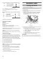
Cleaning Your Washer
Cleaning the Door Seal/Bellow
1. Open the washer door and remove any clothing or items
from the washer.
2. Inspect inner glass door. If debris is present, wipe off debris
using damp cloth.
3. Inspect the colored seal/bellow between the door opening
and the drum for stained areas. Pull back the seal/bellow
to inspect all areas under the seal/bellow and to check
for foreign objects.
A
A. Seal/Bellow
4. If stained areas are found, wipe down these areas of the seal/
bellow, using the procedure that follows:
a) Mix a dilute solution, using 3/4 cup (177 mL) of liquid
chlorine bleach, and 1 gal. (3.8 L) of warm tap water.
b) Wipe the seal/bellow area with the dilute solution,
using a damp cloth.
c) Let stand 5 minutes.
d) Wipe down area thoroughly with a dry cloth and let
the washer interior air dry with door open.
IMPORTANT:
■ Wear rubber gloves when cleaning for prolonged periods.
■ Refer to the bleach manufacturer’s instructions for proper use.
If cycle counter (9 0C) is selected, the following is true:
This is “VIEW ONLY” and cannot be cleared.
Press the
LOWER MIDDLE
key pad once to advance
to next code.
If money counter (1.0C or 1.C0) is selected, the following
is true:
END OF SET-UP PROCEDURES
EXIT FROM SET-UP MODE
PD Models:
Reinstall access door.
PR Models:
1. Unplug washer or disconnect power.
2. Open console, reinsert plug into AA1, close console.
3. Plug in washer or reconnect power.
PR MODELS SET UP AS PN WITH PROGRAMMING SWITCH:
Turn key clockwise and remove.
PR MODELS SET UP AS PN WITHOUT PROGRAMMING
SWITCH:
Set-up mode can be exited by using procedures from Service
Access Code (Below).
SERVICE ACCESS CODE
This code can be entered to access service mode without
removing the console. It only functions on washers set up for
0 vend price without any Special Pricing set-up, and the Coin/
Debit Option must be set to “J._d”. If the washer is not in
failure mode, the door must be opened to proceed. Service
Access Code contains four steps. Perform the following steps:
1. Press the upper left key pad.
2. Press the lower right key pad.
3. Press the upper right key pad.
4. Press the lower left key pad.
NOTE: If the Service Access Code procedure is not completed
properly, as noted above, there is a 15 second delay before it
can be attempted again.
There are three options to exit from the Service Mode:
1. From Set-up Code 8, press the lower left (Temperature)
key pad for 4 seconds.
2. Wait 2 minutes without touching any key pads (without
diagnostic modes running).
3. Power down the washer, then reapply power.
1 00 Represents the number
of cycles in HUNDREDS
1 02 = 200
2 00 Represents the number
of cycles in ONES
2 25 = 25
TOTAL CYCLES = 225
3 00 Number of dollars
in HUNDREDS
3 01 = $100.00
4 00 Number of dollars in ONES
4 68 = $ 68.00
5 00 Number of CENTS
5 75 = $ .75
TOTAL = $168.75
WASHER CARE

15
Washer Maintenance Procedure
This washer has a special cycle that uses higher water volumes
in combination with liquid chlorine bleach to thoroughly clean
the inside of the washer.
NOTES:
■ Read these instructions completely before beginning
the cleaning process.
■ If necessary, the cleaning cycle may be interrupted by
pressing the
UPPER RIGHT
key pad twice. However, this will
not immediately stop the cycle. The washer will continue
with several rinse and drain steps to ensure that all remaining
bleach is rinsed from the washer.
Begin procedure
1. Open the washer door and remove any clothing or items
from the washer.
2. Use liquid chlorine bleach:
Open the dispenser drawer and immediately add
2/3
cup (160 mL) of liquid chlorine bleach to the bleach
compartment.
NOTE: Do not add any detergent to this cycle. Use of more
than
2/3
cup (160 mL) of bleach will cause product damage
over time.
3. Close the washer door and the dispenser drawer.
4. To start the Clean Washer cycle, rst enter “Start Operating
Set-up.” Then press and hold the
UPPER RIGHT
key pad for
1second. With the entire display ashing, press
BRIGHTS
.
NOTE: The door will lock, the drum will rotate a 1/2 turn,
then the door will unlock, lock again, and then the cycle
will continue.
■ The washer will not ll, but the drum will rotate while
the washer runs a short sensing cycle. This will take
approximately 3 minutes.
5. The cycle will determine whether clothing or other items are
in the washer.
a) If no items are detected in the washer, it will proceed
to Step 7.
b) If any items are detected in the washer, “rL” or “F-34”
will be displayed. Then the door will unlock.
■ Press the
UPPER RIGHT
key pad to cancel the failure
code. Then repeat steps 1, 3, and 4 to start the cycle
again.
6. Once the cycle has begun, allow the cycle to complete.
7. After the cycle is complete, leave the door open slightly,
to allow for better ventilation and drying of washer interior.
Always do the following to maintain washer freshness:
■ Use only “HE” High Efciency detergent.
■ Leave the door slightly open after each cycle to allow
for better ventilation and drying of washer interior.
■ Clean the washer monthly using the Washer Maintenance
Procedure and 2/3
cup (160 mL)
of liquid chlorine bleach.
■ If the procedure does not sufciently improve the washer
freshness, please evaluate your installation and usage
conditions for other causes.
Cleaning the exterior
Use a soft damp cloth or sponge to wipe up any spills.
Occasionally wipe the outside of your washer to keep it looking
new. Use mild soap and water. Do not use abrasive products.
Cleaning the dispenser drawer
The dispenser drawer is removable for easy cleaning.
1. Unlock the dispenser drawer by pressing the release lever.
Remove the drawer.
2. Remove the inserts (the siphon from the softener and bleach
compartments).
3. Wash the parts under running water.
NOTE: Do not wash components in the dishwasher.
4. Re-install the inserts and return the dispenser to the drawer.
Water Inlet Hoses
Replace water inlet hoses after 5 years of use to reduce the risk
of hose failure. Periodically inspect and replace water inlet hoses
if bulges, kinks, cuts, wear, or leaks are found.
When replacing your water inlet hoses, mark the date
of replacement.
ASSISTANCE OR SERVICE
If you need assistance:
Contact the distributor where the washer was purchased; locate
an authorized Maytag Commercial Laundry distributor or visit
www.maytagcommerciallaundry.com.
When you call, have the washer model number and serial
number. Both numbers can be found on the serial/rating plate
located on your washer.

MAYTAG COMMERCIAL LAUNDRY LIMITED WARRANTY
MHN33PDCWW, MHN33PDCXW, MHN33PDCGW, MHN33PRCWW, MHN33PNCGW,
MLE22PDAYW, MLG22PDAWW, MLE22PDAZW, MLE22PRAYW, MLG22PRAWW,
MLE22PRAZW, MLE22PDAGW, MLG22PDAGW, MLE22PNAGW, MLG22PNAGW
1. All other costs including labor, transportation, shipping, or custom duties
for covered parts.
2. Factory specified replacement parts if this commercial appliance is
used for other than normal, commercial use or when it is used in a manner
that is inconsistent to published user or operator instructions and/or
installation instructions.
3. Service calls to correct the installation of your commercial appliance,
to instruct you on how to use your commercial appliance, to replace
or repair house fuses, or to correct external wiring or plumbing.
4. Service calls to repair or replace appliance light bulbs, air filters, or water
filters. Consumable parts are excluded from warranty coverage.
5. Damage resulting from improper handling of product during delivery,
theft, accident, alteration, misuse, abuse, fire, flood, acts of God,
improper installation, installation not in accordance with local electrical
or plumbing codes, or use of products not approved by Maytag.
6. Pick up and delivery. This commercial appliance is designed to be
repaired on location.
7. Repairs to parts or systems resulting from unauthorized modifications
made to the commercial appliance.
8. The removal and reinstallation of your commercial appliance if it is
installed in an inaccessible location or is not installed in accordance
with published installation instructions.
9. Damage resulting from exposure to chemicals.
10. Changes to the building, room, or location needed in order to make the
commercial appliance operate correctly.
11. Factory specified replacement parts on commercial appliances with
original model/serial numbers that have been removed, altered, or cannot
be easily determined.
12. Discoloration, rust, or oxidation of stainless steel surfaces.
13. Factory specified replacement parts as a result of incorrect diagnosis
or repair by an “unauthorized” service company.
14. Replacement parts during the sixth through seventh years from the date
of original purchase where the commercial appliance is installed, operated
and maintained in a setting other than a vended and/or multi-housing
environment.
15. Replacement parts during the sixth through seventh years from the
date of original purchase where the defective part is not preventing the
functioning of the product.
The cost of repair or replacement under these excluded circumstances
shall be borne by the customer.
FIVE YEAR LIMITED WARRANTY
(PARTS ONLY — LABOR NOT INCLUDED)
For the first five years from the original date of purchase,
when this commercial appliance is installed, maintained,
and operated according to the instructions attached to
or furnished with the product, Maytag brand of Whirlpool
Corporation (hereafter “Maytag”) will pay for factory
specified replacement parts to correct defects in materials
or workmanship that existed when this commercial appliance
was purchased. This limited warranty does not include labor.
SIXTH THROUGH SEVENTH YEAR LIMITED WARRANTY
(CERTAIN COMPONENT PARTS ONLY –
LABOR NOT INCLUDED)
In the sixth through seventh years from the date of original
purchase, when this commercial appliance is installed,
operated, and maintained in a vended and/or multi-housing
environment ONLY according to instructions attached to
or furnished with the product, Maytag will pay for factory
specified replacement parts for the following components to
correct non-cosmetic defects in materials or workmanship
in the part that prevent functioning of the product and that
existed when this commercial appliance was purchased.
This is a limited 7-year warranty on the below named parts
only and does not include labor.
Washer only: Drive Bearings, Tub Seal, Bearing Spacer, Hub,
Cross Piece, Drum, Rear Tub, Front Tub, Drum Shaft
YOUR SOLE AND EXCLUSIVE REMEDY UNDER THIS
LIMITED WARRANTY SHALL BE PART REPLACEMENT AS
PROVIDED HEREIN. Maytag recommends that you use an
“authorized” service provider to diagnose and repair your
Commercial Laundry product. Maytag will not be responsible
under this warranty to provide additional replacement parts as
a result of incorrect diagnosis or repair by an “unauthorized”
service company. Except in the European Union, this limited
warranty is valid only when the commercial appliance is used
in the country in which it was purchased. This limited warranty
is effective from the date of the original consumer purchase.
Proof of original purchase date is required to obtain service
under this limited warranty.
DISCLAIMER OF IMPLIED WARRANTIES
IMPLIED WARRANTIES, INCLUDING ANY IMPLIED WARRANTY OF MERCHANTABILITY OR IMPLIED WARRANTY OF FITNESS FOR A
PARTICULAR PURPOSE, ARE LIMITED TO SEVEN YEARS OR THE SHORTEST PERIOD ALLOWED BY LAW. Some locations may not allow
limitations on the duration of implied warranties of merchantability or fitness, so this limitation may not apply to you. This warranty gives
you specific legal rights, and you also may have other rights that vary.
LIMITATION OF REMEDIES; EXCLUSION OF INCIDENTAL AND CONSEQUENTIAL DAMAGES
YOUR SOLE AND EXCLUSIVE REMEDY UNDER THIS LIMITED WARRANTY SHALL BE PRODUCT REPAIR AS PROVIDED HEREIN.
MAYTAG SHALL NOT BE LIABLE FOR INCIDENTAL OR CONSEQUENTIAL DAMAGES. Some locations do not allow the exclusion or limitation
of incidental or consequential damages, so these limitations and exclusions may not apply to you. This warranty gives you specific legal rights,
and you also may have other rights that vary by location.
DISCLAIMER OF REPRESENTATIONS OUTSIDE OF WARRANTY
Maytag makes no representations about the quality, durability, or need for service or repair of this major appliance other than the
representations contained in this Warranty. If you want a longer or more comprehensive warranty than the limited warranty that comes
with this major appliance, you should ask your retailer about buying an extended warranty. The benefits to you given by this warranty
are in addition to other rights and remedies available to you under a law in relation to the goods or service to which this warranty relates.
Please contact Maytag for further information on warranty terms.
09/17
SEVEN YEAR LIMITED WARRANTY
WHAT IS COVERED
WHAT IS NOT COVERED
IF YOU NEED SERVICE:
Contact your authorized Maytag Commercial Laundry distributor.
To locate your authorized Maytag Commercial Laundry distributor,
visit www.MaytagCommercialLaundry.com.
For written correspondence:
Maytag Commercial Laundry Service Department
2000 N M 63
Benton Harbor, Michigan 49022-2632 USA
1
6

17
SÉCURITÉ DE LA LAVEUSE

18
EXIGENCES D’INSTALLATION
Autres pièces
Il se peut que l’installation nécessite des pièces supplémentaires.
Pour acheter l’un des articles indiqués ici, composer le numéro
sans frais indiqué à la section “Assistance ou service”.
Si vous avez Vous devrez acheter
Évier de buanderie ou
tuyau rigide de rejet à
l’égout plus haut que
96" (2,4 m)
Système de pompe de puisard
(si non déjà disponible)
Égout surélevé Évier de vidange standard de
20 gal. (76 L) de 30" (762 mm) de
hauteur ou évier utilitaire et pompe
de puisard (disponibles chez votre
fournisseur local d’articles de
plomberie)
Égout au plancher Brise-siphon, pièce n° 285834;
tuyau de vidange additionnel,
pièce n° 8318155; et ensemble
de connexion, pièce n° 285835
Tuyau de vidange trop
court
Trousse de rallonge du tuyau de
vidange de 4 pi (1,2 m), pièce n°
285863
Robinets d’eau hors
d’atteinte des tuyaux
d’admission
2 tuyaux d’admission d’eau plus
longs :
6 pi (1,8 m), pièce n° 76314
10 pi (3,0 m), pièce n° 350008
Outillage et pièces
Rassembler les outils et pièces nécessaires avant de commencer
l’installation. Les pièces fournies se trouvent dans le tambour
de la laveuse.
Outils nécessaires au raccordement des tuyaux
d’arrivée d’eau :
■ Pince (ouverture jusqu’à
1
9
⁄16" [39,5 mm])
■ Lampe de poche
(facultative)
Outils nécessaires à l’installation :
■ Clés plates de 1/2"
(13 mm) et 9/16" (14 mm)
■ Tournevis de sécurité
TORX T20
®†
■ Tourne-écrou de 1/4"
(6 mm)
■ Niveau
■ Cale en bois
■ Règle ou mètre ruban
Pièces fournies :
AB
F
G
C
DE
Accessoires
Vous pouvez faciliter l’utilisation de votre laveuse avec
ces accessoires de première qualité.
Pour vous informer au sujet des autres articles de qualité
ou pour commander, composer le 1-800-807-6777
ou consulter le site Internet www.maytagparts.ca.
Numéro de produit Accessoire
8212526 Plateau d’égouttement de la laveuse,
convient à tous les modèles
31682 Produit de nettoyage polyvalent pour
appareils ménagers
1903WH Casier de rangement de fournitures
de buanderie
A. Bride de retenue pour tuyau
de vidange (en forme de U)
B. Tuyaux d’arrivée d’eau (2)
C. Rondelles pour tuyau
d’arrivée d’eau (4)
†
®
TORX et T20 sont les marques déposées de Acument Intellectual Properties, LLC.
D. Bouchons pour les trous
des boulons de transport (4)
E. Attache de xation amovible
F. Tuyau de vidange
G. Bride de tuyau
Pièces fournies pour les modèles PD :
Came de verrouillage
de la porte de service
Pièces fournies pour les modèles PR :
Biseau de lecteur de carte Vis (2)

19
Dégagements de séparation à respecter
■ L’emplacement doit être assez grand pour permettre
d’ouvrir complètement la porte de la laveuse.
■ Prévoir davantage d’espace pour faciliter l’installation
et l’entretien. La porte s’ouvre à plus de 90° et n’est pas
réversible.
■ Un espace supplémentaire peut être requis pour les
moulures de porte et de plancher et pour les plinthes.
■ Un espace supplémentaire de 1" (25 mm) de tous les
côtés de la laveuse est recommandé pour réduire le
transfert du bruit.
■ Il faut aussi prendre en compte l’espace requis entre
les appareils voisins.
Dimensions de la laveuse
50
1
/2"
(1282 mm)
37
13
/16"
(961 mm)
27"
(686 mm)
28
13
/16"
(732 mm)
44
5
/8"
(1134 mm)
La porte n’est pas réversible.
Un système de vidange au plancher doit être installé sous la
cloison. Des cloisons pré-fabriquées avec prises de courant,
canalisations d’arrivée d’eau, et aménagements pour installation
de vidange ne doivent être installés que là où les codes locaux
l’autorisent.
Exigences d’emplacement
Le choix d’un emplacement approprié pour la laveuse
en améliore le rendement et réduit au minimum le bruit
et le “déplacement” possible de la laveuse.
La laveuse peut être installée sous un comptoir personnalisé,
dans un sous-sol, une salle de buanderie ou un encastrement.
Voir “Système de vidange”.
Il faut aussi prendre en compte les exigences d’emplacement des
appareils voisins. C’est à l’utilisateur qu’incombe la responsabilité
de réaliser une installation correcte.
Il vous faudra
■ Un chauffe-eau conguré pour fournir de l’eau à 120°F
(49°C) à la laveuse.
■ Une prise électrique reliée à la terre située à moins de
6 pi (1,8 m) du cordon d’alimentation électrique xé à l’arrière
à la laveuse. Voir “Spécications électriques”.
■ Des robinets d’eau chaude et d’eau froide situés à moins
de 4 pi (1,2 m) des robinets d’admission d’eau chaude
et d’eau froide et une pression d’eau de 20–100 lb/po²
(137,9–689,6 kPa).
■ Un plancher de niveau ayant une pente maximale de
1" (25 mm) sous l’ensemble de la laveuse. L’installation de
la laveuse sur des surfaces de sol olles telles qu’un tapis
ou des surfaces avec sous-couche en mousse n’est pas
recommandée.
■ Un plancher robuste et solide capable de soutenir le poids
total de la laveuse (eau et charge) de 400 lb (180 kg).
Ne pas faire fonctionner la laveuse à des températures inférieures
à 32ºF (0ºC). Une quantité d’eau peut demeurer dans la laveuse
et causer des dommages à des températures basses.
Options
Piédestal
Vous avez la possibilité d’acheter des piédestaux séparément
pour cette laveuse. Le piédestal augmentera la hauteur totale
de la laveuse.
Piédestal facultatif
Hauteur du
piédestal
Hauteur
approximative
avec laveuse
Couleur
Numéro
de modèle
2
7
⁄8" (73 mm) 47,5" (1207 mm) Blanc WHP0400VW
REMARQUE : Certains modèles comportent un piédestal
pré-installé.

20
Système de vidange
La laveuse peut être installée en utilisant le système de rejet
à l’égout (au plancher ou mural), le système de vidange de
l’évier de buanderie ou le système de vidange au plancher.
Sélectionner la méthode d’installation du tuyau de vidange
selon les besoins. Voir “Outillage et pièces”.
Système de vidange avec tuyau de rejet à l’égout –
mural ou au plancher (vues A et B)
Le système de rejet à l’égout nécessite un tuyau rigide d’un
diamètre minimum de 2" (50 mm). La capacité minimale
d’acheminement ne doit pas être inférieure à 10 gal. (38 L)
par minute et par laveuse.
Le sommet du tuyau rigide de rejet à l’égout doit être au moins
à 30" (762 mm) de hauteur et au maximum à 96" (2,4 m) de la
base de la laveuse.
30" min.
(762 mm)
Système de vidange avec évier de buanderie
L’évier de buanderie doit avoir une capacité minimale de
20 gal. (76 L). La partie supérieure de l’évier de buanderie
doit être à au moins 30" (762 mm) au-dessus du plancher.
Système de vidange au plancher
Le système de vidange au plancher nécessite un brise-siphon
qui peut être acheté séparément. Voir “Outillage et pièces”.
Le brise-siphon doit être au moins à 28" (710 mm) de la base
de la laveuse. Des tuyaux supplémentaires peuvent être requis.
Spécifications électriques
■ Une alimentation de 120 volts, 60 Hz, CA seulement,
de 15 ou 20 ampères, protégée par un fusible est requise.
On recommande d'utiliser un fusible ou un disjoncteur
temporisé. Il est recommandé de raccorder la laveuse
sur un circuit distinct exclusif à cette laveuse.
■ Cette laveuse comporte un cordon d’alimentation électrique
à trois broches pour liaison à la terre.
■ Pour minimiser les risques de choc électrique, on doit
brancher le cordon sur une prise de courant de conguration
correspondante, à 3 alvéoles, reliée à la terre et installée
conformément aux codes et règlements locaux. Si une
prise de courant de conguration correspondante n’est pas
disponible, le client a la responsabilité et l’obligation de
faire installer par un électricien qualié une prise de courant
correctement reliée à la terre.
■ Si les codes le permettent et si on utilise un conducteur
distinct de liaison à la terre, il est recommandé qu’un
électricien qualié vérie la qualité de la liaison à la terre.
■ Ne pas utiliser une tuyauterie de gaz pour le raccordement
à la terre.
■ En cas de doute quant à la qualité de la liaison à la terre
de la laveuse, consulter un électricien qualié.
■ Ne pas installer un fusible dans le conducteur neutre
ou le conducteur de liaison à la terre.
A B
30" min.
(762 mm)
28" min.
(710 mm)
30" min.
(762 mm)
28" min.
(710 mm)
La page est en cours de chargement...
La page est en cours de chargement...
La page est en cours de chargement...
La page est en cours de chargement...
La page est en cours de chargement...
La page est en cours de chargement...
La page est en cours de chargement...
La page est en cours de chargement...
La page est en cours de chargement...
La page est en cours de chargement...
La page est en cours de chargement...
La page est en cours de chargement...
La page est en cours de chargement...
-
 1
1
-
 2
2
-
 3
3
-
 4
4
-
 5
5
-
 6
6
-
 7
7
-
 8
8
-
 9
9
-
 10
10
-
 11
11
-
 12
12
-
 13
13
-
 14
14
-
 15
15
-
 16
16
-
 17
17
-
 18
18
-
 19
19
-
 20
20
-
 21
21
-
 22
22
-
 23
23
-
 24
24
-
 25
25
-
 26
26
-
 27
27
-
 28
28
-
 29
29
-
 30
30
-
 31
31
-
 32
32
-
 33
33


Maytag MHN33PDCWW Guide d'installation
- Catégorie
- Machines à laver
- Taper
- Guide d'installation
dans d''autres langues
- English: Maytag MHN33PDCWW Installation guide
Documents connexes
-
Maytag MVW18MNAWW0 Guide d'installation
-
Maytag MAT20PDAWW Guide d'installation
-
-
-
-
-
-