LG LP073CDUC Le manuel du propriétaire
- Catégorie
- Climatiseurs split-system
- Taper
- Le manuel du propriétaire

P/NO : MFL67646802
Rev.02_082417
www.lg.com
http://www.lghvac.com
Copyright © 2017 LG Electronics Inc. All Rights Reserved.
Copyright © 2017 LG Electronics Inc. Tous droits réservés.
Copyright © 2017 LG Electronics Inc. Todos los Derechos Reservados.
Please read this manual carefully before operating
your set and retain it for future reference.
TYPE : Room Air Conditioner
ENGLISH ESPAÑOL FRANÇAIS
OWNER'S MANUAL
AIR
CONDITIONER

2 Room Air Conditioner
Packaged Terminal Air Conditioner/Heat Pump Owner's Manual
TABLE OF CONTENTS
FOR YOUR RECORDS
Write the model and serial numbers here:
Model #
Serial #
Dealer's Name
Date Purchased
Staple your receipt to this page in the event you need it
to prove date of purchase or for warranty issues.
READ THIS MANUAL
Inside you will find many helpful hints on how to use and
maintain your air conditioner properly. Just a little
preventive care on your part can save you a great deal of
time and money over the life of your air conditioner.
You'll find many answers to common problems in the chart
of troubleshooting tips. If you review our chart of
Troubleshooting Tips first, you may not need to call for
service at all.
PRECAUTION
• Contact an authorized service technician for repair or
maintenance of this unit.
• Contact the installer for installation of this unit.
• The air conditioner is not intended for use by young
children or invalids without supervision.
• Young children should be supervised to ensure that
they do not play with the air conditioner.
• When the power cord is to be replaced, replacement
work shall be performed by authorized personnel
only using only genuine replacement parts.
• Installation work must be performed in accordance
with the National Electric Code by qualified and
authorized personnel only.
You can find them on quality label and front of base pan of
each unit.
Safety Precautions..........................3
Before Operation.............................7
Introduction ....................................8
Electrical Safety ..............................9
Installation .....................................11
Control Locations .........................13
Maintenance and Service ............19

Ownerʼs Manual 3
ENGLISH
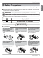
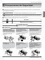
Safety Precautions
Safety Precautions
Incorrect operation due to ignoring instruction will cause harm or damage. The seriousness
is classified by the following indications.
Meanings of symbols used in this manual are as shown below.
WARNING
CAUTION
This symbol indicates the possibility of death or serious injury.
This symbol indicates the possibility of injury or damage to properties only.
Following instructions must be followed to prevent injury to the user and property damages.
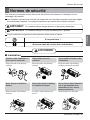
WARNING
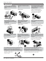
n Installation
Don't do this!
Be sure to follow the instruction.
Donʼt use a power cord, a
plug, or a loose socket
which is damaged.
• It may cause a fire or electrical
shock.
Always plug into a grounded
outlet.
• It may cause a fire or electrical
shock.
Do not modify or extend the
power cord length.
• It will cause electric shock or fire
due to heat generation.
Do not disassemble or
modify products.
• It may cause failure and
electric shock.
Be caution when unpacking
and installing.
• Sharp edges may cause
injury.
Do not use the power cord near
flammable gas or combustibles
such as gasoline, benzene,
thinner, etc.
• It may cause explosion or fire.
Gasolin

4 Room Air Conditioner
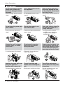
Safety Precautions
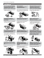
n Operation
Do not place the power cord
near a heater.
• It may cause fire and electric
shock.
Do not allow water to run
into electric parts.
• It will cause failure of machine or
electric shock.
Use a soft cloth to clean. Do
not use wax, thinner, or a
strong detergent.
• The appearance of the air
conditioner may deteriorate,
change color, or develop
surface flaws.
Wax
Thinner
Ventilate the room well when
using this appliance
together with a stove, etc.
• Oxygen depletion could occur.
Turn off the power and
breaker when cleaning the
unit.
• Moving parts could cause injury.
Turn off the main power
switch when not using it for
a long time.
• Prevent accidental startup and
the possibility of injury.
Unplug the unit if strange
sounds, odors, or smoke
come from it.
• It could represent a fire hazed.
Do not open the suction
inlet grill of the product
during operation.
• Otherwise, it may electrical
shock and failure.
If water enters the product, turn
off the the power switch of the
main body of appliance. Contact
service center after taking the
power plug out from the socket.
Do not place objects on the
power cord. Protect the
cord from being pinched or
damaged.
• There is danger of fire or electric
shock.
Use a dedicated circuit for
this appliance.
• An overloaded circuit is a fire
hazard.
Take the power plug out if
necessary, holding the end
of the plug and do not touch
it with wet hands.
• It may cause a fire or electrical
shock.

Ownerʼs Manual 5
ENGLISH
Safety Precautions
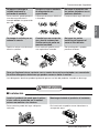
CAUTION
n Installation
Do not operate or stop the
unit by inserting or pulling
out the power plug.
• It will cause electric shock or fire
due to heat generation.
Do not damage or use an
unspecified power cord.
• It will cause electric shock or fire.
Do not operate with wet
hands or in damp
environment.
• It will cause electric shock.
Hold the plug by the end
when taking it out.
• It may cause electric shock and
damage.
When gas leaks, open the
window for ventilation
before operating the unit.
• Otherwise, it may cause an
explosion and a fire.
Never touch the metal parts
of the unit when removing
the filter.
• They are sharp and may cause
injury.
Install the product so that the noise or
exhaust from the outdoor unit may not
cause any damage to the neighbors.
• Be considerate of your neighbor.
Be sure the product is level front-to-back
and side-to-side when installing.
• It may cause vibration or water leakage.
For inner cleaning, contact an Authorized Service Center or a dealer.
Do not use harsh detergent that causes corrosion or damage on the unit.
• Harsh detergent may also cause failure of product, fire, or electronic shock.

6 Room Air Conditioner
Safety Precautions
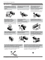
n Operation
Be cautious not to touch the
sharp edges when installing.
• A severe cut or other injury could result.
Avoid excessive cooling and
perform ventilation sometimes.
• Use the ventilation function to circulate
air without cooling or heating
Do not insert hands or other
objects through the air inlet or
outlet during operation.
• Electrical and moving parts could cause
shock or injury.
If the liquid from the batteries gets onto your skin or
clothes, wash it well with clean water. Do not use the
remote if the batteries have leaked.
• The chemicals in batteries could cause burns or other health
hazards.
If you eat the liquid from the batteries, brush your teeth
and see doctor. Do not use the remote if the batteries
have leaked.
• The chemicals in batteries could cause burns or other health
hazards.
Do not put a pet or house plant
where it will be exposed to direct
air flow.
• It is not good to sit in the draft.
Do not block the inlet or outlet of
air flow.
• It may cause product failure.
Use a soft cloth to clean. Do not
use wax, thinner, or a strong
detergent.
• The appearance of the air conditioner
may deteriorate, change color, or
develop surface flaws.
Do not step on the indoor/outdoor
unit and do not put anything on it.
• It may cause an injury through dropping
of the unit or falling down.
Always insert the filter securely.
Clean it every two weeks.
• Operation without filters will cause
failure.
Do not drink water drained from
the air conditioner.
• It contains every contaminant
condensed from the air and could cause
health issues.

Ownerʼs Manual 7
ENGLISH
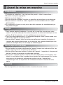
Before Operation
Before Operation
1. Contact an installation specialist for installation.
This is NOT a do-it-yourself project.
2. Plug in the power plug properly.
3. Use a dedicated circuit.
4. Do not use an extension cord. Consult a professional installer or electrician.
5. Do not start/stop operation by plugging/unplugging the power cord.
6. If the cord/plug is damaged, replace it with only an authorized replacement
part.
1. Being exposed to direct airflow for an extended period of time could be
hazardous to your health. Do not expose occupants, pets, or plants to direct
airflow for extended periods of time. In other words, don't sit in the draft.
2. Due to the possibility of oxygen deficiency, ventilate the room when used
together with stoves or other heating devices.
3. Do not use this air conditioner for non-specified special purposes (e.g.
preserving precision devices, food, pets, plants, and art objects). Such usage
could damage the items.
1. Do not touch the metal parts of the unit when removing the filter. Injuries can
occur when handling sharp metal edges.
2. Do not use water to clean inside the air conditioner. Exposure to water can
destroy the insulation, leading to possible electric shock.
3. When cleaning the unit, first make sure that the power and breaker are turned
off. The fan rotates at a very high speed during operation. There is a
possibility of injury if the unitʼs power is accidentally triggered on while
cleaning inner parts of the unit.
For repair and maintenance, contact your authorized service dealer.
Preparing for Operation
Usage
Cleaning and Maintenance
Service

8 Room Air Conditioner
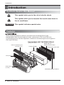
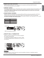
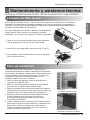
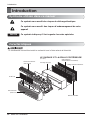
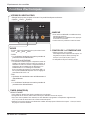
Introduction
This symbol alerts you to the risk of electric shock.
This symbol alerts you to hazards that could cause harm to
the air conditioner.
This symbol indicates special notes.
NOTICE
This air conditioner should be installed in accordance with the National Electric Code.
Expanded Metal Grille Should be applied for better performance in PTAC and PTHP Units.
For Installation purpose and better appearance Aluminium or Architectural grille can be applied in
PTAC and PTHP Units.
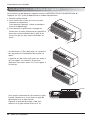
INDOOR
REAR GRILLE
(Aluminum Rear Grille)
Architecture Rear Grille
EXPANDED METAL GRILLE
SLEEVE ASSEMBLY
THE SLEEVE AND THE REAR GRILLE
(Available as an option)
VERTICAL AIR DEFLECTOR
(Horizontal Louver)
AIR FILTER
FRONT GRILLE
(Air Intake)
Introduction
Symbols Used in this Manual
Features

Ownerʼs Manual 9
ENGLISH
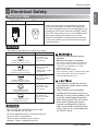
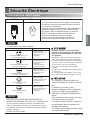
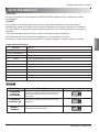
Electrical Safety
Electrical Safety
Electrical Data
208/230V~ 265V~
Power cord may include a current interrupter device.
A test and reset button is provided on the plug case.
The device should be tested on a periodic basis by first
pressing the TEST button and then the RESET button.
If the TEST button does not trip or if the RESET button
will not stay engaged, discontinue use of the air
conditioner and contact a qualified service technician.
*In the case of 265V power cord doesn’t have current
interrupter device.
Use Wall Receptacle Power Supply
Standard 208/230V, 3-wire
grounding receptacle rated 15A
Standard 208/230V, 3-wire
grounding receptacle rated 20A
Standard 208/230V, 3-wire
grounding receptacle rated 30A
Standard 265V grounding
receptacle rated 20A
Standard 265V grounding
receptacle rated 30A
Use 15 AMP. time
delay fuse or 15 AMP.
Circuit breaker.
Use 20 AMP. time
delay fuse or 20 AMP.
Circuit breaker.
(2500W Heater ơ15AMP.
Circuit Breaker)
Use 30 AMP. time
delay fuse or 30 AMP.
Circuit breaker.
Use 20 AMP. time
delay fuse or 20 AMP.
Circuit breaker.
Use 30 AMP. time
delay fuse or 30 AMP.
Circuit breaker.
Never push the test button during
operation
Otherwise this plug can damaged.
This device contains chemicals, including
lead, known to the State of California to
cause cancer, birth defects, or other
reproductive harm.
Wash hands after handling.
Do not remove, modify, or immerse this plug.
If this device trips, the cause should be
corrected before further use.
The conductors inside this cord are
surrounded by shields, which monitor
leakage current.
These shields are not grounded.
Periodically examine the cord for any
damage. Do not use this product in the
event the shields become exposed.
Avoid shock hazard! This unit cannot
be serviced. Opening the tamper-
resistant, sealed portion of the unit
voids all warranties and performance
claims. This unit is not intended to be
an ON/OFF switch.
The shape may be different according to its model.
NOTICE
DO NOT USE AN EXTENSION CORD on 230,
208, and 208/230, 265 Volt units.
All wiring should be made in accordance with local
electrical codes and regulations.
Aluminum house wiring may pose special
problems. Consult a qualified electrician.
NOTICE

10 Room Air Conditioner
Electrical Safety
IMPORTANT
(PLEASE READ CAREFULLY)
FOR THE USER'S PERSONAL SAFETY, THIS
APPLIANCE MUST BE PROPERLY GROUNDED
The power cord of this appliance is equipped with a
three-prong (grounding) plug. Use this with a standard
three-slot (grounding) wall power outlet to minimize
the hazard of electric shock. The customer should
have the wall receptacle and circuit checked by a
qualified electrician to make sure the receptacle is
properly grounded.
DO NOT CUT OR REMOVE THE THIRD (GROUND)
PRONG FROM THE POWER PLUG.
A. SITUATIONS WHEN THE APPLIANCE WILL BE
DISCONNECTED OCCASIONALLY
Because of potential safety hazards, we strongly
discourage the use of an adapter plug. However, if
you wish to use an adapter, a TEMPORARY
CONNECTION may be made. Use UL-listed adapter,
available from most local hardware stores.
The large slot in the adapter must be aligned with the
large slot in the receptacle to assure a proper polarity
connection.
Attaching the adapter ground terminal to the wall
receptacle cover screw does not ground the
appliance unless the cover screw is metal, and not
insulated, and the wall receptacle is grounded
through the house wiring. The customer should
have the circuit checked by a qualified electrician to
make sure the receptacle is properly grounded.
Disconnect the power cord from the adapter, using
one hand on each. Otherwise, the adapter ground
terminal might break. DO NOT USE the appliance with
a broken adapter plug.
B. SITUATIONS WHEN THE APPLIANCE WILL BE
DISCONNECTED OFTEN
Do not use an adapter plug in these situations.
Unplugging the power cord frequently can lead to an
eventual breakage of the ground terminal. The wall
power outlet should be replaced by a three-slot
(grounding) outlet instead.
USE OF EXTENSION CORDS
Because of potential safety hazards, we strongly
discourage the use of an extension cord. However, if
you wish to use an extension cord, use a CSA
certified/UL-listed 3-wire (grounding) extension cord.
Electrical Safety
WARNING:
Wash hands after handling.
or other reproductive harm.
This product contains chemicals known to
the State of California to cause cancer and birth defects

Ownerʼs Manual 11
ENGLISH
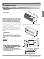
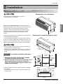
Installation
How to Install the Unit
Installation
406 mm
(16")
1,066 mm
(42")
349 mm
(13
3
/
4
")
536 mm
(21")
Dimension of air conditioner
Dimension of sleeve assembly (optional)
Over 20"
HEAT
RADIATION
WALL
WALL
INSULATION
SLEEVE
INTAKE
AIR
COOLED
AIR
1/4" Bubble
of the level
Over 20"
Front
Insulation Strip
Rear
Sleeve
280 mm
(11")
406 mm
(16")
1066 mm
(42")
349 mm
(13
3
/
4
")
Insulation
Joint Gap
• Need 2 people to lift up air conditioner, it is HEAVY.
For existing sleeve, you should measure the wall sleeve
dimensions.
You can install the new air conditioner according to these
installation instructions to achieve the best performence. All
wall sleeves used to mount the new air conditioner must be in
good structural condition and have the rear grille that securely
attached to the sleeve or the flange of the sleeve to secure the
new air conditioner.
• To avoid vibration and noise, make sure the unit is installed
securely and firmly.
When installing the sleeve & Front grille, make certain there is
nothing within 21” back & front of sleeve & front grille, that
would interfere with heat radiation and exhaust air flow.
• Before installation, Check the insulation on the inner side of
the sleeve. If there is no insulation, place the insulation.
• Check the bottom corner's joint gap of the sleeve, If there is,
fill the gap with putty.
To maintain the best performance
of LG PTAC
1. An insulation strip must be attached. The
insulation strip is provided with the box.
2. After assembly of sleeve & front grille, the
gap should be over 20” from both sleeve &
grille. For assembly PTAC Model refer the
diagram.
1) Take out the insulation strip from the upper packing.
2) Attach the insulation strip onto the rear upper side of the
wall sleeve.
NOTICE

12 Room Air Conditioner
Installation
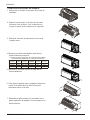
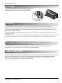
• UNIT INSTALLATION
1. Remove the shipping screw from the ventilation door.
2. Remove the front gille by pulling it out at the bottom
to release it, then lift it up along the unit top front.
6. Slide the unit into the wall sleeve and secure with
4 screws through the unit flange holes.
3. Remove cover by removing 3 screws from front.
7. Reinstall the front grille by hooking the top over the
unit top, then pushing it in at the bottom.
4. Connect accessory power supply cord, and fix power
cord to basepan with screws.
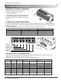
5. Replace cover with screws. Tighten securely.
ELECTRIC HEATER RATING
(CONFIGURATION BASED ON POWER CORD)
POWER CORD
AYUH2115 2 400/2 300 W
230/208
230/208
3 300/3 200 W
230/208
15 A
20 A
30 A4 700/4 600 W
AYUH2120
AYUH2130
VOLTAGE
WATTS
HEATER
CURRENT
HEATER MAX.
FUSE SIZE
MIN.CIRCUIT
AMPACITY
14.5 A
19.8 A
28.3 A
10.5/11.2 A
14.5/15.5 A
20.6/22.3 A

Ownerʼs Manual 13
ENGLISH
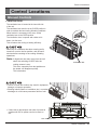
Control Locations
Control Locations
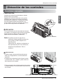
Manual Controls
• VENTILATION
The ventilation lever is located to the lower left side
of the unit.
The ventilation lever must be in the CLOSE position in
order to maintain the best cooling & heating conditions.
When fresh air is necessary in the room, set the
ventilation lever to the OPEN position.
The Ventilation door is opened and outdoor air is
drawn into the room.
This will reduce the cooling or heating efficiency.
When the air conditioner has been running and is
turned off or set to the fan position, wait at least 3
minutes before resetting to the cooling & heating
operations.
Note:
A slight heat odor may come from the unit
when first switching to HEAT after the
cooling season is over.
This odor, caused by fine dust particles on
the heater, will disappear quickly.
This is harmless.
VENT
OPEN
VENT
CLOSE
Ventilation door
• Failure to follow this caution may result in equipment
damage or improper operation.
• Blocking indoor(curtain or bedclothes etc.) or outdoor
discharge air could cause premature failure of unit.
INDOOR
IN
D
OO
R
•
If there has a gap between rear side of product &
outside wall, the air splitter need to be used on
unit.
Sleeve
Wall
Outside Wall
Air Splitter
Rear side of product

14 Room Air Conditioner
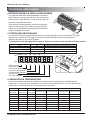
Control Locations
Electronic Controls
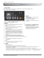
POWER
MODE
-
Push this button to cycle through the modes from
COOL
FAN HEAT COOL.
- COOL
• Fan runs continually for normal cooling operation.
- ENERGY SAVER
• The fan stops when the compressor stops cooling & heating
operations. Approximately every 3 minutes the fan will turn on and
the unit will check the room air temperature to determine if cooling
& heating is needed.
• For Energy saver operation Dip switch #2 is ON position. Refer
Dipswitch setting at P.No 16
- FAN
• Fan operation without heating or cooling.
- HEAT
• Fan runs continually for normal heating operation.
TIMER
- SHUT-OFF TIME
• You will usually use shut-off time while you sleep.
• If unit is running, use Timer to set number of hours until shut-off.
• For your sleeping comfort, once Time is set, the setting temperature will raise 2°F after 30 minutes, and once again
after another 30 minutes.
• Push Timer to cycle through the settings from 1 Hour
2 Hours ... 12 Hours maximum.
FAN SPEED
• Every time you push this button, it cycles through the settings as follows:
{High(F2)
Low(F1) High(F2)}
• To turn ON the air conditioner, push this button.
To turn OFF the air conditioner, push this button
again.
• This button takes priority over any other button.
TEMPERATURE SETTING
• Use this button to automatically control the
temperature of the room.
The temperature can be set within a range of
54°F (12°C) to 86°F (30°C) by increments of
1°F (0.5°C).
• The setting temperature in the display.
°F

Control Locations
Owner’s Manual 15
ENGLISH
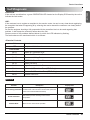
Self-Diagnosis
FUNCTION:
If the unit has a malfunction, a green OPERATION LED located on the Display PCB used by the unit to
indicate the fault codes.
USE:
If the customer has to register a complaint to the service center, he can be very clear about registering
the complaint that what is happening & by referring the user's manual the customer can clearly define
the problem.
So that the engineer should go fully prepared with the prescribed tools to be used regarding that
problem. It also keeps the customer aware about the unit.
Here are some of the problems defined below for which the LED indicates by flashing.
The fault codes are the mentioned which is as follows:
• Electrical Controls
NOTICE
ON Normal
OFF No power / failed board
Fault Codes
CH 01
Indoor Air Thermistor Error
CH 02
Indoor Coil Thermistor Error
CH 07
Themostat Wiring Error
CH 09
EEPROM Check Sum Error
CH 10
Indoor Fan Error
CH 34
High Pressure Switch Error
CH 44
Outdoor Air Thermistor Error (PTHP Only)
CH 45
Outdoor Coil Thermistor Error (PTHP Only)
CH 67
Outdoor Fan Error
Function Description Display code
Over heating Protection
This feature prevents melting of unit by electrical heater
located inside of the unit at the remote mode (when the
unit is connected with wall thermostat).
°F
Freeze Protection
This feature prevents freezing of room at low
temperature.
°F
Remote Mode When use the remote mode operation
°F

16 Room Air Conditioner
Control Locations
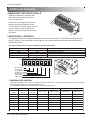
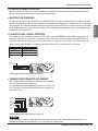
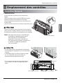
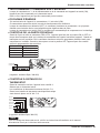
Additional Controls
• REMOVING THE FRONT GRILLE
Additional controls are available after
removing the front grille and option
cover of control box.
To remove the front grille, pull out the
bottom of front grille and then lift up.
To reinstall the front grille, place the tabs
over the top of the unit and push the
bottom of front grille until the clips snap
into place.
• ADDITIONAL CONTROLS
The additional controls are located behind the option cover of control box. The standard settings will be in
the OFF position. The authorized service engineer has to check switches and ensure the switches are in
the desired position.
ON
ONREMOTE
OFF
ON ON ON
Remote/Local
Energy Saver
Temperature Limit 1
Temperature Limit 2
Temperature Limit 3
PTAC/PTHP
UNIT TYPE
LOCAL
1
OFF
2
OFF
3
OFF
4
OFF
5
LOCAL
1
OFF
2
OFF
3
OFF
4
OFF
5
LOCAL
1
OFF
2
OFF
3
OFF
4
OFF
5
LOCAL
1
OFF
2
OFF
3
OFF
4
OFF
5
OFF
6
OFF
7
LOCAL
1
OFF
2
OFF
3
OFF
4
OFF
5
LOCAL
1
OFF
2
OFF
3
OFF
4
OFF
5
OFF OFF OFF 54 F (12.2 C) 86 F (30.0 C)
86 F (30.0 C)
86 F (30.0 C)
86 F (30.0 C)
86 F (30.0 C)
86 F (30.0 C)
86 F (30.0 C)
86 F (30.0 C)
54 F (12.2 C)
54 F (12.2 C)
54 F (12.2 C)
54 F (12.2 C)
54 F (12.2 C)
54 F (12.2 C)
54 F (12.2 C)
54 F (12.2 C)
86 F (30.0 C)
ON OFF OFF 56 F (13.3 C) 84 F (28.9 C)
OFF ON OFF 58 F (14.4 C) 82 F (27.8 C)
ON ON OFF 60 F (15.5 C) 80 F (26.7 C)
OFF )C 5.52( F 87)C 6.61( F 26NOFFO
ON OFF ON 64 F (17.7 C) 76 F (24.4 C)
OFF ON ON 66 F (18.9 C) 74 F (23.3 C)
ON ON ON 68 F (20.0 C) 72 F (22.2 C)
Temperature Temperature Temperature
Limit #1 Limit #2 Limit #3
Lowest Temp. Highest Temp. Lowest Temp. Highest Temp.
Cooling Operation noitarepO gnitaeH5#4#3#
Dip switch setting is done at factory according to product specification.
• TEMPERATURE LIMITING
Temperature Limiting can save money by limiting the lowest temperature for cooling and the highest temperature for heating.
The temperature limiting is controlled by switches #3 - #5.
This temperature limiting is not available with the Remote Wall Thermostat.
#6 #7 Unit Type
OFF OFF Cooling+Electric Heater+Heat Pump
OFF ON Cooling+Electric Heater
ON OFF Heat Pump Only
ON ON Cooling Only

• REMOTE/LOCAL CONTROL
When remote/local switch #1 is on, it allow the unit to operate by the Remote Wall Thermostat.
The unit control by buttons are not available.
• ENERGY SAVER
The energy saver switch #2 is on. This switch is set at cycle fan to provide continuous fan operation in cool
or heat modes. When the switch is off the continuous fan allows continuous circulation of room air and
make the more balanced temperature of the room. When the switch is on, the fan is on or off with the
compressor or with the heater.
• FRONT DESK CONTROL
When the pair wire is connected to the connector FD2 and FD1, the unit can be turned ON or OFF with a
switch located at the Front Desk Control panel. When the front desk switch is ON, the fan operates
according to the setting without working compressor and heater. When the front desk switch is OFF, the unit
can operate according to the setting of controls.
• REMOTE WALL THERMOSTAT
When the wires are connected, the unit will be controlled
by a remote wall thermostat.
The thermostat connections supply the 24 Volt AC. When
you install the digital/electronic thermostat, you
must set it
to 24 Volt AC.
GL GH O W Y R C
Low Fan
High Fan
Reversing Valve
Heater
Compressor
24 Volt-L
24 Volt-N
Wire # AWG Maximum Length
#22 600 ft (180 m)
#20 900 ft (270 m)
#18 1500 ft (450 m)
#16 2000 ft (610 m)
FD2 FD1 DR2 DR1 MS2 MS1
Front Desk Control
Front Desk Control
(Molex Housing Spec 396-06V)
(Molex Housing Spec 396-07V)
Room Air Conditioner 17
Control Locations
ENGLISH
NOTICE
For wiring connection of Wall Thermostat, check the Installation instruction or Installation manual’s
provided by Thermostat Company.

18 Room Air Conditioner
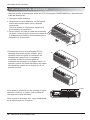
Control Locations
1. Remove the front grille.
2. To remove the front grille, pull out the bottom
of the front grille and then lift up.
Re-install the component by referring to the
removal procedure.
3. To reinstall the front grille, place the tabs over
the top of the unit and push the bottom of front
grille until the clips snap into place.
• This Room Air Conditioner (PTAC) discharges
air from the top of the unit through reversible, 2-
position discharge grille louvers. The unit is
shipped from the factory with the discharge grille
louvers at an angle of 40” off vertical. In an
alternate position the louvers will be at an angle
of 15” off vertical.
To adjust the air direction, remove the front
grille. Remove the 4 screws that fasten the
discharge grille to the front grille.
Rotate the discharge grille 180°, then assembly the
discharge grille to the front grille with 4 screws.
Disassembly Instructions
- Before the following disassembly, POWER SWITCH is set to OFF and disconnected the power
cord.
Screws
INDOOR
INDOOR
40˚
15˚
INDOOR

Maintenance and Service
Ownerʼs Manual 19
Maintenance and Service
Air Filter Cleaning
Vent Filter
TURN OFF THE AIR CONDITIONER AND REMOVE THE PLUG FROM THE POWER OUTLET.
The air filter should be checked at least twice a month to see if cleaning is necessary.
Trapped particles in the filter will build up and block the airflow. This reduces the cooling
capacity and also causes an accumulation of frost on the cooling coils.
If the filter becomes turn or damaged you should replace
immediately. Replacement filters are available from your
salesperson, dealer, and the authorized customer service
centers.
1. Remove the air filter from the front grille assembly by
pulling the air filter up slightly.
2. Wash the filter using lukewarm water below 104° F(40°C).
3. Gently shake the excess water from the filter completely.
Reinstall the filter.
Before cleaning the vent filter, disconnect power to the
unit by unplugging the power cord at the wall outlet or
subbase, or disconnect power at the fuse box or circuit
breaker. If unit is operated with vent door closed, the
vent filter does not need to be cleaned.
1. Remove the front grille as described in front grille
Removal.
2. Remove the 4 screws securing the chassis to the
wall sleeve with a Phillips-Head screwdriver.
3. Slide the chassis out of the wall sleeve far enough so
that the vent filter is accessible as shown in Figure A.
4. Remove the vent filter by unscrewing the two screws
at the top of the filter and gently pulling the filter away
from the partition panel. Refer to Figure B.
5. Clean and reinstall the filter by reattaching the hook
to the bottom of the vent door and replacing the two
screws, slide the chassis back into the wall sleeve,
secure it in place with 4 screws and reinstall the
front cabinet.
Figure A – Vent (Left side of unit)
Figure B – Vent Filter Removal
INDOOR
ENGLISH

20 Room Air Conditioner
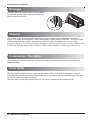
Maintenance and Service
Chassis
Front Grille
Compressor / Fan Motor
The chassis must be cleaned every four months or more often as the atmospheric conditions
require. Use water and detergent to clean the basepan, center partition and coils. The use of harsh
cleaning materials may cause a deterioration of the coil fins or endplates. Do not use a high
pressure cleaner as it could cause severe damage to the PTAC fins and coils. A hose is okay to use
to clean the coils, but make sure to cover the control with a blanket or plastic bag to keep it dry.
The base pan may overflow due to high humidity.
To drain the excess water, remove the drain cap
from the back of the unit.
The compressor and fan motor are hermetically sealed, permanently lubricated, and require no
additional oiling.
The Front Grille and discharge air grille can be cleaned with a mild soap or detergent. Under no
circumstances should hydrocarbon based cleaners (e.g. acetone, benzene, naphtha, gasoline, etc.)
be used to clean the front or air grilles.
Use care when cleaning the control area. Do not use an excessively wet cleaning cloth.
Drainage
Drain Cap
La page est en cours de chargement...
La page est en cours de chargement...
La page est en cours de chargement...
La page est en cours de chargement...
La page est en cours de chargement...
La page est en cours de chargement...
La page est en cours de chargement...
La page est en cours de chargement...
La page est en cours de chargement...
La page est en cours de chargement...
La page est en cours de chargement...
La page est en cours de chargement...
La page est en cours de chargement...
La page est en cours de chargement...
La page est en cours de chargement...
La page est en cours de chargement...
La page est en cours de chargement...
La page est en cours de chargement...
La page est en cours de chargement...
La page est en cours de chargement...
La page est en cours de chargement...
La page est en cours de chargement...
La page est en cours de chargement...
La page est en cours de chargement...
La page est en cours de chargement...
La page est en cours de chargement...
La page est en cours de chargement...
La page est en cours de chargement...
La page est en cours de chargement...
La page est en cours de chargement...
La page est en cours de chargement...
La page est en cours de chargement...
La page est en cours de chargement...
La page est en cours de chargement...
La page est en cours de chargement...
La page est en cours de chargement...
La page est en cours de chargement...
La page est en cours de chargement...
La page est en cours de chargement...
La page est en cours de chargement...
La page est en cours de chargement...
La page est en cours de chargement...
La page est en cours de chargement...
La page est en cours de chargement...
La page est en cours de chargement...
La page est en cours de chargement...
La page est en cours de chargement...
La page est en cours de chargement...
-
 1
1
-
 2
2
-
 3
3
-
 4
4
-
 5
5
-
 6
6
-
 7
7
-
 8
8
-
 9
9
-
 10
10
-
 11
11
-
 12
12
-
 13
13
-
 14
14
-
 15
15
-
 16
16
-
 17
17
-
 18
18
-
 19
19
-
 20
20
-
 21
21
-
 22
22
-
 23
23
-
 24
24
-
 25
25
-
 26
26
-
 27
27
-
 28
28
-
 29
29
-
 30
30
-
 31
31
-
 32
32
-
 33
33
-
 34
34
-
 35
35
-
 36
36
-
 37
37
-
 38
38
-
 39
39
-
 40
40
-
 41
41
-
 42
42
-
 43
43
-
 44
44
-
 45
45
-
 46
46
-
 47
47
-
 48
48
-
 49
49
-
 50
50
-
 51
51
-
 52
52
-
 53
53
-
 54
54
-
 55
55
-
 56
56
-
 57
57
-
 58
58
-
 59
59
-
 60
60
-
 61
61
-
 62
62
-
 63
63
-
 64
64
-
 65
65
-
 66
66
-
 67
67
-
 68
68


LG LP073CDUC Le manuel du propriétaire
- Catégorie
- Climatiseurs split-system
- Taper
- Le manuel du propriétaire
dans d''autres langues
- English: LG LP073CDUC Owner's manual
- español: LG LP073CDUC El manual del propietario