GE GFD14ESSNWW Le manuel du propriétaire
- Catégorie
- Sèche-linge
- Taper
- Le manuel du propriétaire

GE is a trademark of the General Electric Company. Manufactured under trademark license.
0020507767GE 49-3000087 Rev 1 10-19 GEA
DRYERS
SAFETY INFORMATION ..........3
USING THE DRYER
Getting Started ...................... 4
Loading ..............................8
Features ..............................8
CARE AND CLEANING ...........9
INSTALLATION
INSTRUCTIONS .....................11
Stacking (Optional) .....................24
Reversing The Door Swing (Optional). . . . . 26
TROUBLESHOOTING TIPS ......28
LIMITED WARRANTY ...........31
CONSUMER SUPPORT ..........32
GFD14
OWNER’S MANUAL &
INSTALLATION
INSTRUCTIONS
Write the model and serial
numbers here:
Model # _________________
Serial # _________________
They are on the label on the front
of the dryer behind the door.
ENGLISH/FRANÇAIS/
ESPAÑOL

2 49-3000087 Rev 1
THANK YOU FOR MAKING GE APPLIANCES A PART OF YOUR HOME.
Whether you grew up with GE Appliances, or this is your first, we’re happy to have you in the family.
We take pride in the craftsmanship, innovation and design that goes into every GE Appliances
product, and we think you will too. Among other things, registration of your appliance ensures that we
can deliver important product information and warranty details when you need them.
Register your GE appliance now online. Helpful websites and phone numbers are available in the
Consumer Support section of this Owner’s Manual. You may also mail in the pre-printed registration
card included in the packing material.

49-3000087 Rev 1 3
READ AND SAVE THESE INSTRUCTIONS
IMPORTANT SAFETY INFORMATION
READ ALL INSTRUCTIONS BEFORE USING THE APPLIANCE
To reduce the risk of fire, explosion, electric shock, or injury to persons when using your appliance,
follow basic precautions, including the following:
Ŷ
Read all instructions before using the appliance.
Ŷ
DO NOT dry articles that have been previously cleaned in, washed in, soaked in, or spotted with gasoline,
dry-cleaning solvents, or other flammable or explosive substances, as they give off vapors that could ignite or
explode.
Ŷ
DO NOT place items exposed to cooking oils in your dryer. Items contaminated with cooking oils may contribute to a
chemical reaction that could cause a load to catch fire. To reduce the risk of fire due to contaminated loads, the final
part of the tumble dryer cycle occurs without heat (cool down period). Avoid stopping a tumble dryer before the end
of the drying cycle unless all items are quickly removed and spread out so that the heat is dissipated.
Ŷ
DO NOT allow children to play on or in this appliance. Close supervision of children is necessary when this
appliance is used near children.
Ŷ
Before the appliance is removed from service or discarded, remove the door to the drying compartment.
Ŷ
DO NOT reach into the appliance if the drum is moving.
Ŷ
DO NOT install or store this appliance where it will be exposed to the weather.
Ŷ
DO NOT tamper with controls.
Ŷ
DO NOT climb or stand on this unit.
Ŷ
DO NOT repair or replace any part of this appliance or attempt any servicing unless specifically recommended
in the user-maintenance instructions or in published user-repair instructions that you understand and have the
skills to carry out.
Ŷ
Follow all fabric care instructions and warnings to prevent melting of garments or damage to the appliance.
Ŷ
DO NOT use fabric softeners or products to eliminate static unless recommended by the manufacturer of the
fabric softener or product.
Ŷ
DO NOT dry articles containing foam rubber or similarly textured rubber-like materials.
Ŷ
Clean lint screen before or after each load.
Ŷ
DO NOT operate the dryer without the lint filter in place.
Ŷ
D O N O T store combustible materials, gasoline or other flammable liquids near the dryer. Keep area around the
exhaust opening and adjacent surrounding areas free from the accumulation of lint, dust and dirt.
Ŷ
The interior of the appliance and exhaust duct should be cleaned periodically by qualified service personnel.
Ŷ
Unplug the appliance or turn off the circuit breaker before servicing. Pressing the Power or Start/Pause button DOES
NOT disconnect power.
Ŷ
DO NOT operate this appliance if it is damaged, malfunctioning, partially disassembled, or has missing or
broken parts, including a damaged cord or plug.
Ŷ
DO NOT spray any type of aerosol into, on or near dryer at any time. DO NOT use any type of spray cleaner when
cleaning dryer interior. Hazardous fumes or electrical shock could occur
.
Ŷ
See “ELECTRICAL CONNECTION” located in the Installation Instructions for grounding instructions.
WARNING
SAFETY INFORMATION

4 49-3000087 Rev 1
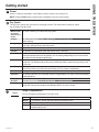
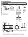
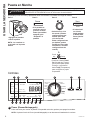
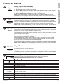
Getting started
USING THE DRYER
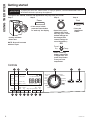
Throughout this manual, features and appearance may vary from your model.
Controls
• If the screen is dark,
press the Power button
to “wake up” the display.
Step 2 Step 3
Step 4
Step 1
• Select a dry cycle.
(Defaults are set for
each dry cycle. These
default settings can
be changed. See
control settings for
more information.)
OR
• Press the
Start/Pause
button.
• Loosely add items.
• Close door.
NOTE: Dryer will not start
with door open.
To reduce the risk of fire, electric shock, or injury to persons, read the IMPORTANT SAFETY
INFORMATION before operating this appliance.
WARNING
Power
• Press Timed Dry
button, rotate knob
to adjust time, and
press Temp button
to set your own
temperature.
Start
Pause
Temp
Timed
Dry
Damp DelayDamp
Dry
Ex Dry
Damp Timed
Clean Filter
No Heat
Low
High
Medium
DRY DAMP COOL
Est Time Remaining
Tumble
My Cycle
Power
Start
Pause
Warm Up
Rack Dry
Quick Dry
Delicates
Cottons
Heavy
Duty
Active
Wear
Casuals
To w e l s
Sanitize
Dewrinkle
Mixed Loads
Timed
Dry
Damp
Alert
Level
Ext
Tumble
My Cycle
Temp eDry
Hold to Set
Delay
Dry
Low Air eDry
C
L AKBM
D E F H I J
N
G

49-3000087 Rev 1 5
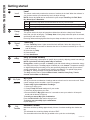
USING THE DRYER
Getting started
B
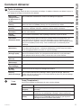
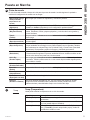
Dry Cycles
The dry cycle controls the cycle time for the drying process. The chart below will help you match
the dry setting with the loads.
Mixed Loads
or Normal
(Depending on
model)
For loads consisting of cottons and poly blends.
Cottons For cottons and most linens. NOTE: Energy Star
®
models are tested on Cottons with
default settings.
Heavy Duty For large coats, bed spreads, mattress covers, sleeping bags, blankets, comforters, jackets,
small rugs, and similar large and bulky items.
Towels Use for towels OR sheets. It is not recommended to mix towels and sheets in the same load.
Casuals For wrinkle-free, permanent press and delicate items, and knits.
Active Wear Clothing worn for active sports exercise and some casual wear. Fabrics include new technology
finishes and stretch fibers such as Spandex. Also for clothing labeled Easy Care or Perma Press:
For wrinkle-free and permanent press items.
Sanitize Reduces certain types of bacteria by 96.7%, including: Staphylococcus aureus and Pseudomonas
aeruginosa. The antibacterial process occurs when high heat is used during a portion of this
drying cycle.
Quick Dry For small loads that are needed in a hurry, such as sports or school uniforms. Can also be
used if the previous cycle left some items damp, such as collars or waistbands.
Delicates For lingerie and special-care fabrics.
Dewrinkle For removing wrinkles from items that are dry or slightly damp. This cycle is not recommended
for delicate fabrics.
Warm Up Provides 25 minutes of warming time to warm up clothes.
Air Fluff Provides 30 minutes of tumbling time without heat.
Rack Dry For drying delicate items without tumbling, use drying rack accessory. Place items flat on the
drying rack such as wool sweaters and delicate fabrics. Dry with low heat.
A
Power
Press to “wake up” the display. If the display is active, press to turn the dryer off.
NOTE: Pressing Power does not disconnect the appliance from the power supply.
C
Temp (Temperature)
You can change the temperature of your dry cycle.
Temp
High For regular to heavy cottons.
Medium For synthetics, blends and items labeled Permanent Press.
Low For delicates, synthetics and items labeled Tumble Dry Low.
No Heat This option may only be used with Air Fluff and Timed Dry, in which items are
tumbled without heat.

6 49-3000087 Rev 1
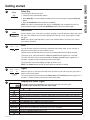
Getting started
USING THE DRYER
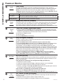
Extended Tumble
Minimizes wrinkles by adding approximately 2 hours of no-heat tumbling after clothes are
dry.
The estimated time remaining display will show “END”.
The extended tumble time does not get added to the cycle time on the display.
I
D
Level
The sensor continuously monitors the amount of moisture in the load. When the moisture in
your clothes reaches your selected dry level, the dryer will stop.
NOTE: Sensor dry Level can be used with all cycles except Timed Dry, Air Fluff, Rack
Dry, Warm Up and Dewrinkle.
E
Damp Alert
This option causes the dryer to beep when clothes have dried to a damp level. Remove
items that you wish to hang dry. The Damp Alert will only beep when this option is selected,
and the dryer will continue to dry.
Removing clothes and hanging them when they are damp can reduce the need to iron some items.
Damp
Alert
F
Timed Dry
1. Press Timed Dry button. Lights around the knob will flash. Select the drying time by
rotating the knob to increase or decrease the time in 10-minute increments up to 2 hours
and 30 minutes.
2. Select the dry Temp.
3. Close the door.
4. Press Start/Pause.
H
My Cycle
Set up your favorite combination of settings and save them here for one touch recall. These
custom settings can be set while a cycle is in progress.
To store a My Cycle combination of settings:
1. Select your drying cycle.
2.
Change Temp and Level settings to fit your needs.
3. Select any drying options you want.
4. Press and hold the My Cycle button for 3 seconds to store your selection. A beep will
sound and the button will light up.
To recall your stored My Cycle combination:
Press the MY CYCLE button before drying a load.
To change your stored My Cycle combination:
Repeat steps 1–4.
My Cycle
Hold to Set
Level
Ex Dry Use for heavy-duty fabrics or items that should be very dry, such as towels.
Dry Use for normal dryness level suitable for most loads. This is the preferred cycle for energy saving.
Damp For leaving items partially damp.
Timed
Dry
Tumble
Ext
G
eDry (on some models)
Reduces total energy consumption of specific dryer cycles by adjusting certain heat settings.
NOTE: Cycle times will change when eDry is selected.
Energy Star
®
models are tested on Cottons cycle with default settings to determine energy
use rating of this dryer. The eDry option will default to on for Cottons. Temperature settings
on High and dryness level setting on Dry are specifically designed for this cycle to reduce
energy consumption. For optimal energy savings, turn eDry on. For optimal drying times,
turn eDry off. Energy savings will vary across loads and cycles.
The eDry selection can be used with Mixed Loads, Cottons, Heavy Duty, Towels,
Casuals, Active Wear and Delicates.
eDry

49-3000087 Rev 1 7
USING THE DRYER
Getting started
J
Delay Dry
Use to delay the start of your dryer.
1. Choose your dry cycle and any options.
2. Press Delay Dry. You can change the delay time in 1 hour increments, using the Delay Dry
button.
3. Press the Start/Pause button to start the countdown.
NOTE: If the door is opened while the dryer is in Delay Dry, the countdown time will not
restart unless the door is closed and Start/Pause button has been pressed again.
K
Start/Pause
Press to start a cycle. If the dryer is running, pressing it once will pause the dryer and unlock
the door. This function can be used to add garments during a cycle. Press again to restart
the cycle.
NOTE: If the dryer is paused and the cycle is not restarted within 15 minutes, the current
cycle will be cancelled.
L
Lock
You can lock the controls to prevent any selections from being made. Or you can lock or
unlock the controls after you have started a cycle.
Children cannot accidentally start the dryer by touching pads with this option selected.
To lock the dryer, press and hold the Temp and Level buttons together for 3 seconds.
To unlock the dryer controls, press and hold the Temp and Level buttons together for 3
seconds. A sound is made to indicate the lock/unlock status.
The control lock icon on the display will light up when it is on.
NOTE: The Power button can still be used when the machine is locked.
Level
Temp
Start
Pause
M
Signal
When the light is on, the dryer will beep at the end of the cycle and every time you press a
button on the control panel.
To turn the signal off, press and hold the Damp Alert and Timed Dry buttons together for 3
seconds. A sound is made to indicate the lock/unlock status.
Delay
Dry
Timed
Dry
Damp
Alert
N
Display and Status Lights
The display shows the approximate time remaining until the end of the cycle.
In addition, this display will show the dryer status:
Damp DelayDamp
Dry
Ex Dry
Damp Timed
Clean Filter
No Heat
Low
High
Medium
DRY DAMP COOL
Est Time Remaining
Tumble
My Cycle
LowAir eDry
Status
DRY DAMP COOL
Controls locked on.
End of cycle signal on.
Clean Filter Time to clean the filter. See the Care and Cleaning section.
Low Air Indicates decrease in performance of the dryer and increase risk of lint accumulation in the ducts and
dryer.
eDry Shows eDry setting selected.
Temp Shows High, Medium, Low or No Heat temperature setting selected.
Level Shows Extra Dry, Dry or Damp dryness setting selected.
Damp Alert Indicates Damp Alert is set and will sound when the clothes have dried to a damp dryness level.
Timed Indicates that a Timed Dry cycle is set. Will turn off after cycle is finished.
Est Time
Remaining
Display shows the estimated time remaining until set cycle is completed.
My Cycle Indicates the My Cycle feature is set.
Ext Tumble Indicates the Extended Tumble feature is set.
Indicates Delay Dry is set time is selected.

8 49-3000087 Rev 1
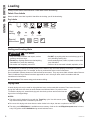
Loading
USING THE DRYER
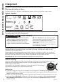
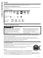
Fabric Care Labels
Below are fabric care label “symbols” that affect the clothing you will be laundering.
Dry Labels
Always follow fabric manufacturer’s care label when laundering.
As a general rule, if clothes are sorted properly for the washer, they are sorted properly for the dryer. Try also to
sort items according to size. For example, do not dry a sheet with socks or other small items.
Do not add fabric softener sheets once the load has become warm. They may cause fabric softener stains. Bounce
®
Fabric Conditioner Dryer Sheets have been approved for use in this dryer when used in accordance with the
manufacturer’s instructions.
Do not overload. This wastes energy and causes wrinkling.
• Keep flammable materials and vapors, such as
gasoline, away from dryer.
• DO NOT dry anything that has ever had anything
flammable on it (even after washing).
• No washer can completely remove oil.
• DO NOT dry anything that has ever had any type of oil
on it (including cooking oils).
• Items containing foam, rubber, or plastic must be dried
on a clothesline.
• Failure to do so can result in death, explosion, or fire.
Sorting and Loading Hints
Tumble
dry
Dry
Normal
Permanent Press/
wrinkle resistant
Gentle/
delicate
Do not tumble dry
Do not dry
(used with
do not wash)
Heat
setting
High Medium Low No heat/air
Special
instructions
Line dry/
hang to dry
Drip dry
Dry flat
In the shade
- Fire Hazard
WARNING
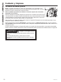
Drying Rack
A handy drying rack may be used for drying delicate items such as washable sweaters. Place items flat on the
drying rack and block such items as wool sweaters and delicate fabrics. Dry with low heat.
To install the drying rack, extend the drying rack into the dryer drum and rest the front two
legs on the front angled ledge.
NOTES:
Ŷ
The drying rack is designed for use with the Timed Dry cycle. Use with sensor cycles
may result in damp items or extended cycle times.
Ŷ
Do not use this drying rack when there are other clothes in the dryer, that are not placed on the rack.
Ŷ
The drying rack, WE01X26416, is available as an accessory. Order on-line at GEApplianceparts.com, 24 hours
a day or by phone at 877.959.8688 during normal business hours.

49-3000087 Rev 1 9
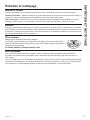
CARE AND CLEANING
Care and cleaning
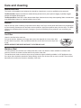
Exterior
Wipe or dust any spills or washing compounds with a damp cloth. Dryer control panel and finishes may be damaged
by some laundry pretreatment soil and stain remover products. Apply these products away from the dryer. The fabric
may then be washed and dried normally. Damage to your dryer caused by these products is not covered by your
warranty.
Stainless Steel
To clean stainless steel surfaces use a damp cloth with a mild, non-abrasive cleaner suitable for stainless steel
surfaces. Remove the cleaner residue and then dry with a clean cloth.
The stainless steel used to make the dryer drum provides the highest reliability available in a GE Appliances dryer.
If the dryer drum should be scratched or dented during normal use, the drum will not rust or corrode. These surface
blemishes will not affect the function or durability of the drum.
Interior and Duct
The interior of the appliance and exhaust duct should be cleaned once a year by qualified service personnel.
The Exhaust Duct: Inspect and clean the exhaust ducting at least once a year to prevent clogging. A partially clogged
exhaust can lengthen the drying time.
The Exhaust Hood: Check with a mirror that the inside flaps of the hood move freely when operating. Make sure that there
is no wildlife (birds, insects, etc.) nesting inside the duct or hood.
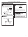
Lint Filter
Clean the lint filter before each use.
Pull out the lint filter. Moisten your fingers and remove the captured lint. Once clean, slide
the filter back into position. Have a qualified technician vacuum the lint from the dryer once
a year.
NEVER OPERATE THE DRYER WITHOUT ITS FILTER IN PLACE.

10 49-3000087 Rev 1
Care and cleaning
CARE AND CLEANING
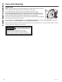
Drum Lamp
NOTE: The drum lamp is not consumer replaceable on models where there is a flat cover
over an LED bulb. If this light should ever stop working, call for service.
For models that have a domed cover over the bulb secured by a screw:
Before replacing the light bulb, be sure to unplug the dryer power cord or disconnect the
dryer at the household distribution panel by removing the fuse or switching off the circuit
breaker. Reach above dryer opening from inside the drum to locate the light.
Remove the screw and the plastic cover to access the bulb. Replace with the appropriate
bulb and then reaffix the cover and screw.
Order replacement bulb WE11X26351 on-line at GEApplianceparts.com, by phone at 877.959.8688 during normal
business hours, or purchase appliance bulb 7C7 from your local retailer.
When the door is opened, the drum lamp automatically turns on and remains on for 2 minutes. When the door is closed,
the drum lamp will remain on for 30 seconds.
Disconnect power supply before servicing.
Replace all parts and panels before operating.
Failure to do so can result in death or electrical shock.
- Electrical Shock Hazard
WARNING

49-3000087 Rev 1 11
Installation
Dryer
Instructions
If you have any questions, call GE Appliances at 800.GE.CARES
(800.432.2737)
or visit our Website at: GEAppliances.com
In Canada, call 800.561.3344
or visit www.GEAppliances.ca
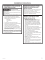
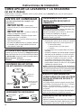
BEFORE YOU BEGIN
Read these instructions completely and carefully.
• IMPORTANT – Save these instructions for
local electrical inspector’s use.
• IMPORTANT – Observe all governing
codes and ordinances.
• Install the clothes dryer according to the
manufacturer’s instructions and local codes.
• Note to Installer – Be sure to leave these
instructions with the Consumer.
• Note to Consumer – Keep these instructions for
future reference.
• Clothes dryer installation must be performed by a
qualified installer.
• This dryer must be exhausted to the outdoors.
• Before the old dryer is removed from service or
discarded, remove the dryer door.
• Service information and the wiring diagram are
located in the control console.
• Do not allow children on or in the appliance. Close
supervision of children is necessary when the
appliance is used near children.
• Proper installation is the responsibility of the installer.
• Product failure due to improper installation is not
covered under the Warranty.
• Install the dryer where the temperature is above
50°F for satisfactory operation of the dryer control
system.
• Remove and discard existing plastic or metal foil
duct and replace with UL-listed duct.
- Risk of Fire
• Clothes dryer installation must be performed by a
qualified installer.
• Install the clothes dryer according to these
instructions and local codes.
• DO NOT install a clothes dryer with flexible plastic
venting materials. If flexible metal (semi-rigid or
foil-type) duct is installed, it must be UL-listed and
installed in accordance with the instructions found
in “Connecting the Dryer to House Vent” later in
this manual. Flexible venting materials are known
to collapse, be easily crushed and trap lint. These
conditions will obstruct dryer airflow and increase
the risk of fire.
• DO NOT install or store this appliance in any
location where it could be exposed to water or
weather.
• To reduce the risk of severe injury or death, follow
all installation instructions.
• Save these instructions. (Installers: Be sure to
leave these instructions with the customer.)
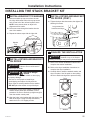
If you are planning to stack the washer and dryer, order
Stacking Kit number GFA24KITL to be used for this
dryer. Kit sold separately.
WARNING

12 49-3000087 Rev 1
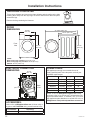
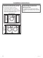
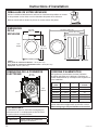
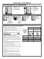
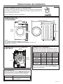
*NOTE:
With leveling legs retracted: 33-1/4 (84.5 cm)
With leveling legs fully extended: 33-5/8 (85.4 cm)
Stacked: 66-1/2” (168.9 cm)
Installation Instructions
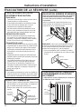
Tilt the dryer sideways and remove the foam shipping pads by pulling at the sides and
breaking them away from the dryer legs. Be sure to remove all of the foam pieces
around the legs.
Remove the bag containing the literature.
UNPACKING YOUR DRYER
DRYER
DIMENSIONS
*33-1/4”
(84.5 cm)
Side View
25-1/4” (64.1 cm)
42-13/16” (108.7 cm)
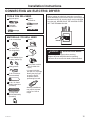
ELECTRICAL CONNECTION
DIMENSIONS
POWER CORDS
GE Appliances strongly recommends the use of
factory specified parts. Select the power cord to fit your
installation requirements.
Order on-line at GEApplianceparts.com today,
24 hours a day or by phone at 877.959.8688 during
normal business hours. In Canada, visit your local
GE Appliances parts distributor or call 800.661.1616
or
GEAppliances.ca/en/products/parts-filters-accessories.
Part Number Type Length Amperage
WX9X2 3-Prong 4 Feet 30
WX9X3 3-Prong 5 Feet 30
WX9X4 3-Prong 6 Feet 30
WX9X18 4-Prong 4 Feet 30
WX9X19 4-Prong 5 Feet 30
WX9X20 4-Prong 6 Feet 30
Back
View
30”
(76.2 cm)
20-1/2”
(52.1 cm)
Front
View
23-7/16”
(59.5 cm)
*33-1/4”
(84.5 cm)
ACCESSORIES:
Order on-line at GEApplianceParts.com, 24 hours a day or
by phone at 877.959.8688 during normal business hours.
Part Number Accessory
PM08X10085
Flexible Metal Dryer Transition Duct

49-3000087 Rev 1 13
Installation Instructions
MOBILE OR MANUFACTURED
HOME INSTALLATION
• Installation MUST conform to the
MANUFACTURED HOME CONSTRUCTION
AND SAFETY STANDARD, TITLE 24, PART
3280 or STANDARD FOR MOBILE HOMES
CAN/CSA-Z240 MH, or, when such standards
are not applicable, with AMERICAN NATIONAL
STANDARD FOR MOBILE HOME, ANSI/NFPA
NO. 501B.
• The dryer MUST be vented to the outdoors.
• The exhaust vent MUST be securely fastened to a
non-combustible portion of the mobile home.
• The vent MUST NOT be terminated beneath a
mobile or manufactured home.
• The vent duct material MUST BE METAL.
• KIT 14-D346-33 MUST be used to attach the dryer
securely to the structure.
• The vent MUST NOT be connected to any other
duct, vent or chimney.
• DO NOT use sheet metal screws or other
fastening devices which extend into the interior of
the exhaust vent.
• Provide an opening with a free area of at least 25
square inches for introduction of outside air into
the dryer room.
• See the sections for electrical connection information.
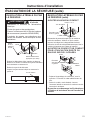
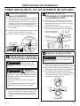
REQUIREMENTS FOR ALCOVE OR
CLOSET INSTALLATION
Keep flammable materials and vapors, such as gasoline,
away from dryer.
Place dryer at least 18” (46 cm) above the floor for a
garage installation.
Failure to do so can result in death, explosion, or fire.
• The dryer MUST be vented to the outdoors.
• Minimum clearance between dryer cabinet and
adjacent walls or other surfaces is:
0” either side
1” front and rear
1” top
• The rear of the dryer should face a wall.
• Consideration must be given to provide adequate
clearance for installation and service.
• Closet doors must be louvered or otherwise
ventilated and have at least 60 square inches of
open area. If the closet contains both a washer
and a dryer, doors must contain a minimum of 120
square inches of open area.
NOTE: WHEN THE EXHAUST DUCT IS LOCATED AT
THE REAR OF THE DRYER, THE CONFIGURATION
OF THE DUCTING MAY REQUIRE GREATER THAN
3” OF REAR CLEARANCE.
MINIMUM CLEARANCE OTHER
THAN ALCOVE OR CLOSET
INSTALLATION
Minimum clearance to combustible surfaces and for
air opening are: 0” both sides, 1” rear and 1” top.
The rear of the dryer should face a wall.
Consideration must be given to provide adequate
clearance for installation and service.
- Explosion Hazard
WARNING

14 49-3000087 Rev 1
Installation Instructions
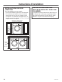
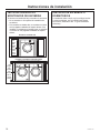
UNDERCOUNTER INSTALLATION
If an undercounter installation is desired:
• No special dryer installation kit is required.
• If the dryer is installed alone, a minimum of 60
square inches of open area is required. If a washer
and dryer are installed together, a minimum of 120
square inches of open area is required.
BATHROOM OR BEDROOM
INSTALLATION
The installation must conform with local codes or,
in the absence of local codes, with the NATIONAL
ELECTRICAL CODE, ANSI/NFPA NO. 70 (for electric
dryers).
60
square
inches
min.
open
area
Dryer Installed Alone
Countertop and side cabinets
Washer and Dryer Installed Together
Countertop and side cabinets
120
square
inches
min.
open
area

49-3000087 Rev 1 15
Installation Instructions
CONNECTING AN ELECTRIC DRYER
Before making the electrical connection, turn off the
circuit breaker(s) or remove the dryer’s circuit fuse(s) at
the electrical box. Be sure the dryer cord is unplugged
from the wall. NEVER LEAVE THE ACCESS COVER
OFF THE TERMINAL BLOCK.
TOOLS YOU WILL NEED
Slip-joint pliers
Flat-blade
screwdriver
Phillips
screwdriver
Level
Disconnect power supply before servicing.
Replace all parts and panels before operating.
Failure to do so can result in death or electrical shock.
- Electrical Shock Hazard
WARNING
MATERIALS YOU WILL NEED
Ŷ
4” dia. metal elbow
Ŷ
3/4” Strain relief
(UL recognized)
Ŷ
4” Duct clamps (2) or
4” spring clamps (2)
Ŷ
Safety glasses
Ŷ
4” dia. metal duct
(recommended)
Ŷ
Gloves
Ŷ
Exhaust hood
Ŷ
Duct tape
Ŷ
4” dia., UL-listed
flexible metal duct
(if needed)
Ŷ
Dryer power cord kit
(not provided with
dryer)
UL rated 120/240V,
30A with 3 or 4 prongs.
Identify the plug type
as per the house
receptacle before
purchasing line cord.
Ŷ
4” Cover Plate
(Kit WE49X22606)
(if needed)
Stacking installations
may require a power
cord up to 6 feet in
length.

16 49-3000087 Rev 1
For direct wire connections:
Use 10 gauge copper wire.
Use a UL-listed strain relief.
Disconnect power before making electrical connections.
Connect neutral wire (white or center wire) to center
terminal.
Ground wire (green or bare wire) must be connected to
green ground connector.
Connect remaining two supply wires to remaining two
terminals.
Securely tighten all electrical connections.
Replace the terminal block cover.
Failure to do so can result in death, fire or electrical shock.
GROUNDING INSTRUCTIONS
For a permanently connected dryer: This dryer
must be connected to a grounded metal, permanent
wiring system, or an equipment-grounding conductor
must be run with the circuit conductors and
connected to the equipment-grounding terminal on
the appliance.
Improper connection of the
equipment-grounding conductor can
result in a risk of electric shock. Check with a qualified
electrician, or service representative or personnel, if
you are in doubt as to whether the appliance is properly
grounded.
SAVE THESE INSTRUCTIONS
- Fire Hazard
WARNING
WARNING
Use a new UL-listed 240V 30 amp dryer power supply
cord with closed ring terminals or spade terminals with
upturned ends.
Use a UL-listed strain relief.
Disconnect power before making electrical connections.
Connect neutral wire (white or center wire) to center
terminal.
Ground wire (green or bare wire) must be connected to
green ground connector.
Connect remaining two supply wires to remaining two
terminals.
Securely tighten all electrical connections.
Replace the terminal block cover.
Failure to do so can result in death, fire or electrical shock.
For electrical connections using a
power cord:
GROUNDING INSTRUCTIONS
For a grounded, cord-connected dryer: This dryer
must be grounded. In the event of a malfunction or
breakdown, grounding will reduce the risk of electric
shock by providing a path of least resistance for
electric current. This dryer uses a cord having an
equipment-grounding conductor and a grounding
plug. The plug must be plugged into an appropriate
outlet that is properly installed and grounded in
accordance with all local codes and ordinances.
Improper connection of the
equipment-grounding conductor can
result in a risk of electric shock. Check with a qualified
electrician, or service representative or personnel, if
you are in doubt as to whether the appliance is properly
grounded. DO NOT modify the plug on the power supply
cord. If it will not fit the outlet, have a proper outlet
installed by a qualified electrician.
SAVE THESE INSTRUCTIONS
- Fire Hazard
WARNING
WARNING
ELECTRICAL CONNECTION
INFORMATION FOR ELECTRIC
DRYERS
ELECTRICAL CONNECTION
INFORMATION FOR ELECTRIC
DRYERS
Installation Instructions
TO PREVENT ELECTRIC SHOCK, DISCONNECT
POWER BEFORE SERVICING.
This dryer should be connected to an individual branch
circuit with 10 gauge copper wire minimum through a
30 amp fuse or circuit breaker. DO NOT fuse neutral.
Use copper conductors only.
- Electrical Shock Hazard
WARNING
TO PREVENT ELECTRIC SHOCK, DISCONNECT
POWER BEFORE SERVICING.
This dryer should be connected to an individual branch
circuit with 10 gauge copper wire minimum through a
30 amp fuse or circuit breaker. DO NOT fuse neutral.
Use copper conductors only.
- Electrical Shock Hazard
WARNING

49-3000087 Rev 1 17
Installation Instructions
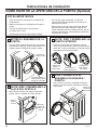
CONNECTING DRYER USING
3-WIRE CONNECTION
CONNECTING DRYER USING
4-WIRE CONNECTION (MUST
BE USED FOR MOBILE HOME
INSTALLATION)
NOTE: Since January 1, 1996, the National Electrical
Code requires that new constructions use a 4-wire
connection to an electric dryer. A 4-wire cord must
also be used where local codes do not permit grounding
through the neutral. 3-wire connection is NOT for use
on new construction.
1. Turn off the circuit breaker(s) (30 amp) or remove
the dryer’s circuit fuse at the electrical box.
2. Be sure the dryer cord is unplugged from the wall
receptacle.
3. Remove the power cord cover located at the upper
back.
4. Remove green ground screw and retain for use in
Step 7. Remove center screw (marked N) in terminal
block. Remove and discard ground strap.
5. Install 3/4 in. UL-recognized strain relief to power
cord entry hole. Bring power cord through strain
relief and bracket.
6. Connect power cord as follows:
A. Connect the 2 hot lines to the outer screws of the
terminal block (marked L1 and L2).
B. Connect the neutral (white) line to the center of
the terminal block (marked N).
7. Attach ground wire of power cord with the green
ground screw (hole above strain relief bracket).
Tighten all terminal block screws (3) securely.
8. Properly secure power cord to strain relief and
bracket.
9. Reinstall the cover.
NEVER LEAVE THE COVER OFF OF THE
TERMINAL BLOCK.
NEVER LEAVE THE COVER OFF OF THE
TERMINAL BLOCK.
3-wire Connection
Not for use in Canada.
DO NOT use for Mobile Home Installations.
NOT for use on new construction.
NOT for use on recreational vehicles.
NOT for use in areas where local codes prohibit
grounding through the neutral conduction.
1. Turn off the circuit breaker(s) (30 amp) or remove
the dryer’s circuit fuse at the electrical box.
2. Be sure the dryer cord is unplugged from the wall
receptacle.
3. Remove the power cord cover located at the upper
back.
4. Install 3/4-in. UL-recognized strain relief to power
cord entry hole. Bring power cord through strain
relief and bracket.
5. Connect power cord as follows:
A. Connect the 2 hot lines to the outer screws of
the terminal block (marked L1 and L2).
B. Connect the neutral (white) line to the center of
the terminal block (marked N).
6. Be sure ground strap is connected to green ground
screw on cabinet rear. Tighten all terminal block
screws (3) securely.
7. Properly secure power cord to strain relief and
bracket.
8. Reinstall the cover.
L1
N
L2
Green wire
from power
cord
3/4” Strain
Relief and
Bracket
Cover
4 #10 AWG minimum copper conductors or 120/240V 30A
power supply cord kit marked for use with dryers and provided
with closed loop or spade terminals with upturned ends (not
supplied).
White Wire
Black
or Red
Wire
Black
or
Red
Wire
If required, by local code, install external ground (not
provided) to grounded metal, cold water pipe, or other
established ground determined by a qualified electrician.
L1
N
L2
Black or Red Wire
3/4” Strain
Relief and
Bracket
Cover
3 #10 AWG minimum copper conductors or 120/240V 30A
power supply cord kit marked for use with dryers and provided
with closed loop or spade terminals with upturned ends (not
supplied).
Ground
Strap
White Wire
Black
or Red
Wire

18 49-3000087 Rev 1
Installation Instructions
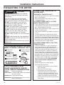
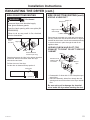
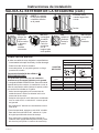
EXHAUSTING THE DRYER
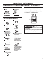
TOOLS AND MATERIALS YOU WILL
NEED TO INSTALL EXHAUST DUCT
CONNECTING THE DRYER TO
HOUSE VENT
RIGID METAL TRANSITION DUCT
• For best drying performance, a rigid metal transition
duct is recommended.
• Rigid metal transition ducts reduce the risk of
crushing and kinking.
UL-LISTED FLEXIBLE METAL CLOTHES
DRYER TRANSITION DUCT
• If rigid metal cannot be used, then UL-listed flexible
metal clothes dryer transition duct (GE Appliances
part – PM08X10085) can be used.
• Never install transition duct in walls, ceilings, floors
or other enclosed spaces.
• Total length of transition duct should not exceed 8’
(2.4 m).
• For many applications, installing elbows at both
the dryer and the wall is highly recommended (see
illustrations in next section). Elbows allow the dryer
to sit close to the wall without kinking and/or crushing
the transition duct, maximizing drying performance.
• Avoid resting the duct on sharp objects.
UL-LISTED FLEXIBLE METAL (FOIL-TYPE)
TRANSITION DUCT
• In special installations, it may be necessary to
connect the dryer to the home exhaust vent
using flexible metal (foil-type) transition duct. UL–
LISTED universal flexible dryer transition duct
(GE Appliances parts – PM8X73 or WX8X73)
may be used ONLY in installations where rigid
metal or flexible metal transition ducting cannot be
used AND where a 4” diameter can be maintained
throughout the entire length of the transition duct.
• In Canada and the United States, only transition
ducts that comply with “UL 2158A STANDARD
FOR CLOTHES DRYER TRANSITION DUCT”
shall be used.
• Avoid resting the duct on sharp objects.
• For best drying performance:
1. Slide one end of the duct over the clothes
dryer outlet pipe.
2. Secure the duct with a clamp.
3. With the dryer in its permanent position,
extend the duct to its full length. Allow 2”
of duct to overlap the exhaust pipe. Cut off
and remove excess duct. Keep the duct as
straight as possible for maximum airflow.
4. Secure the duct to the exhaust pipe with the
other clamp.
Ŷ
Phillips-head
screwdriver
Ŷ
Duct tape or
duct clamp
Ŷ
Rigid or UL-listed flexible
metal 4” (10.2 cm) duct
Ŷ
Drill with 1/8” drill bit
(for bottom venting)
Ŷ
Hacksaw
Ŷ
Vent
hood
This dryer MUST be vented to the outdoors.
Use only 4” rigid metal ducting for the home
exhaust duct.
Use only 4" rigid metal, UL-listed flexible
metal, or UL-listed metal foil dryer transition
duct to connect the dryer to the home exhaust.
DO NOT use any plastic to vent the dryer,
this includes the home exhaust duct, dryer
transition duct, or within the dryer.
DO NOT use flexible metal or metal foil ducting
for a home exhaust duct or within the dryer.
DO NOT exhaust into a chimney, kitchen
exhaust, gas vent, wall, ceiling, attic, crawl
space, or concealed space of a building.
DO NOT install a screen in or over the exhaust
duct.
DO NOT install a booster fan in the exhaust duct.
DO NOT use duct longer than specified in the
exhaust length table.
Failure to follow these instructions can result in
death or fire.
PARTS AVAILABLE FROM
GEAPPLIANCEPARTS.COM OR
LOCAL SERVICE ORGANIZATIONS
PM8X85
Outdoor exhaust hood
PM08X10085
8’ Flexible metal clothes dryer transition
duct with 2 clamps
WX08X10130
4” Dryer exhaust clamp
WE49X22606
Rear exhaust opening cover, for side or
bottom vented dryers
- Fire Hazard
WARNING

49-3000087 Rev 1 19
Installation Instructions
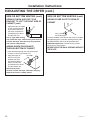
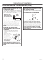
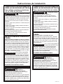
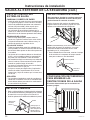
EXHAUSTING THE DRYER (cont.)
Using exhaust longer than specified length will:
• Increase the drying times and the energy cost.
• Reduce the dryer life.
• Accumulate lint, creating a potential fire hazard.
The correct exhaust installation is YOUR
RESPONSIBILITY.
Problems due to incorrect installation are not
covered by the warranty.
The MAXIMUM ALLOWABLE length of the exhaust
system depends upon the type of duct, number of turns,
the type of exhaust hood (wall cap) and all conditions
noted on the chart.
• Internal elbows added for side or bottom vent
conversions must be included in the total elbow count.
• Any elbow greater than 45° should be treated as a 90°
elbow; one elbow of 45° or less may be ignored.
• Two 45° elbows will be treated like one 90° elbow.
• For the side exhaust installations, add one 90° elbow to
the chart.
• For every additional 90° elbow, reduce the allowable
vent system length by 10 feet.
• When calculating the total vent system length, you
must add all the straight portions and elbows of the
system (including the transition duct).
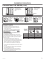
EXHAUST LENGTH
EXHAUST
LENGTH
RECOMMENDED MAXIMUM LENGTH
Exhaust Hood Types
Recommended
Use only for short run
installations
4" DIA.
4"
4" DIA.
4" DIA.
2-1/2"
No. of 90° Elbows Rigid Metal Rigid Metal
0 90 Feet 60 Feet
1 60 Feet 45 Feet
2 45 Feet 35 Feet
3 35 Feet 25 Feet
4 25 Feet 15 Feet
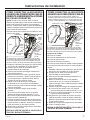
• DO NOT bend
or collapse
ducting.
Use elbows
if turns are
necessary.
• DO NOT use
excessive
exhaust
length. Cut
duct as short
as possible.
• DO NOT
crush duct
against
the wall
.
• DO NOT
set dryer
on duct
.
• DO cut duct as short
as possible and
install straight into
wall.
•
DO use elbows
when turns are
necessary.
Elbows

20 49-3000087 Rev 1
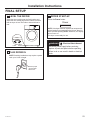
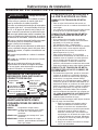
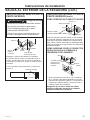
Installation Instructions
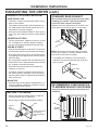
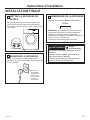
BEFORE YOU BEGIN
• Remove and discard existing plastic or metal foil
duct and replace with UL-listed duct.
• Remove any lint from the wall exhaust opening.
Internal
Duct
Opening
Wall
Check that exhaust
hood damper
opens and closes
freely.
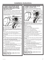
STANDARD REAR EXHAUST
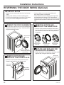
We recommend that you install your dryer before
installing your washer. This will permit direct
access for easier exhaust connection.
Slide the end of the exhaust duct on the back of the
dryer and secure with duct tape or a hose clamp.
NOTE: We strongly recommend using rigid metal
exhaust duct. However, if flexible ducting is used it
must be UL-Listed metal, not plastic.
• For straight line installation, connect the dryer
exhaust to the external exhaust hood using duct
tape or clamp.
RECOMMENDED CONFIGURATION
TO MINIMIZE EXHAUST BLOCKAGE
Using duct elbows will prevent duct kinking and
collapsing.
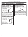
EXHAUST SYSTEM CHECKLIST
HOOD OR WALL CAP
• Terminate in a manner to prevent back drafts or entry of
birds or other wildlife.
• Termination should present minimal resistance to
the exhaust airflow and should require little or no
maintenance to prevent clogging.
• Wall caps must be installed at least 12” above ground
level or any other obstruction with the opening pointed
down.
SEPARATION OF TURNS
• For best performance, separate all turns by at least
4 ft. of straight duct, including distance between
last turn and dampened exhaust hood (wall cap).
SEALING OF JOINTS
• All joints should be tight to avoid leaks. The male end
of each section of duct must point away from the dryer.
• Duct joints should be made air- and moisture-tight
by wrapping the overlapped joints with duct tape or
aluminum tape.
• Do not assemble ductwork with any fasteners that
extend into the duct. These fasteners can accumulate
lint, creating a potential fire hazard.
• Horizontal runs should slope down towards the
outdoors 1/4” per foot.
• Provide an access for inspection and cleaning of
the exhaust system, especially at turns and joints.
Exhaust system shall be inspected and cleaned at
least once a year.
INSULATION
• Ductwork that runs through an unheated area or is
near air conditioning should be insulated to reduce
condensation and lint build-up.
Wall Side
Dryer
Side
Duct Tape
EXHAUSTING THE DRYER (cont.)
Duct
Transition
Ducting
Wall
La page est en cours de chargement...
La page est en cours de chargement...
La page est en cours de chargement...
La page est en cours de chargement...
La page est en cours de chargement...
La page est en cours de chargement...
La page est en cours de chargement...
La page est en cours de chargement...
La page est en cours de chargement...
La page est en cours de chargement...
La page est en cours de chargement...
La page est en cours de chargement...
La page est en cours de chargement...
La page est en cours de chargement...
La page est en cours de chargement...
La page est en cours de chargement...
La page est en cours de chargement...
La page est en cours de chargement...
La page est en cours de chargement...
La page est en cours de chargement...
La page est en cours de chargement...
La page est en cours de chargement...
La page est en cours de chargement...
La page est en cours de chargement...
La page est en cours de chargement...
La page est en cours de chargement...
La page est en cours de chargement...
La page est en cours de chargement...
La page est en cours de chargement...
La page est en cours de chargement...
La page est en cours de chargement...
La page est en cours de chargement...
La page est en cours de chargement...
La page est en cours de chargement...
La page est en cours de chargement...
La page est en cours de chargement...
La page est en cours de chargement...
La page est en cours de chargement...
La page est en cours de chargement...
La page est en cours de chargement...
La page est en cours de chargement...
La page est en cours de chargement...
La page est en cours de chargement...
La page est en cours de chargement...
La page est en cours de chargement...
La page est en cours de chargement...
La page est en cours de chargement...
La page est en cours de chargement...
La page est en cours de chargement...
La page est en cours de chargement...
La page est en cours de chargement...
La page est en cours de chargement...
La page est en cours de chargement...
La page est en cours de chargement...
La page est en cours de chargement...
La page est en cours de chargement...
La page est en cours de chargement...
La page est en cours de chargement...
La page est en cours de chargement...
La page est en cours de chargement...
La page est en cours de chargement...
La page est en cours de chargement...
La page est en cours de chargement...
La page est en cours de chargement...
La page est en cours de chargement...
La page est en cours de chargement...
La page est en cours de chargement...
La page est en cours de chargement...
La page est en cours de chargement...
La page est en cours de chargement...
La page est en cours de chargement...
La page est en cours de chargement...
La page est en cours de chargement...
La page est en cours de chargement...
La page est en cours de chargement...
La page est en cours de chargement...
-
 1
1
-
 2
2
-
 3
3
-
 4
4
-
 5
5
-
 6
6
-
 7
7
-
 8
8
-
 9
9
-
 10
10
-
 11
11
-
 12
12
-
 13
13
-
 14
14
-
 15
15
-
 16
16
-
 17
17
-
 18
18
-
 19
19
-
 20
20
-
 21
21
-
 22
22
-
 23
23
-
 24
24
-
 25
25
-
 26
26
-
 27
27
-
 28
28
-
 29
29
-
 30
30
-
 31
31
-
 32
32
-
 33
33
-
 34
34
-
 35
35
-
 36
36
-
 37
37
-
 38
38
-
 39
39
-
 40
40
-
 41
41
-
 42
42
-
 43
43
-
 44
44
-
 45
45
-
 46
46
-
 47
47
-
 48
48
-
 49
49
-
 50
50
-
 51
51
-
 52
52
-
 53
53
-
 54
54
-
 55
55
-
 56
56
-
 57
57
-
 58
58
-
 59
59
-
 60
60
-
 61
61
-
 62
62
-
 63
63
-
 64
64
-
 65
65
-
 66
66
-
 67
67
-
 68
68
-
 69
69
-
 70
70
-
 71
71
-
 72
72
-
 73
73
-
 74
74
-
 75
75
-
 76
76
-
 77
77
-
 78
78
-
 79
79
-
 80
80
-
 81
81
-
 82
82
-
 83
83
-
 84
84
-
 85
85
-
 86
86
-
 87
87
-
 88
88
-
 89
89
-
 90
90
-
 91
91
-
 92
92
-
 93
93
-
 94
94
-
 95
95
-
 96
96


GE GFD14ESSNWW Le manuel du propriétaire
- Catégorie
- Sèche-linge
- Taper
- Le manuel du propriétaire
dans d''autres langues
- English: GE GFD14ESSNWW Owner's manual
- español: GE GFD14ESSNWW El manual del propietario
Documents connexes
-
GE DCVH480EKWW Le manuel du propriétaire
-
-
-
GE GFD14ESSNWW Manuel utilisateur
-
-
-
GE GFT14ESSMWW Front Load Ventless Condenser Electric Dryer Le manuel du propriétaire
-
-
-
GE GFD55GSPNDG Le manuel du propriétaire
