Allied Telesis AT-MC104LH Guide d'installation
- Catégorie
- Convertisseurs de média réseau
- Taper
- Guide d'installation
Ce manuel convient également à

AT-MC101XL
AT-MC102XL
AT-MC103XL
AT-MC103LH
AT-MC104XL
AT-MC104LH
Fast Ethernet Media Converters
Version 4
Installation Guide
PN 613-000235 Rev A

Copyright © 2005 Allied Telesyn, Inc.
www.alliedtelesyn.com
All rights reserved. No part of this publication may be reproduced without prior written
permission from Allied Telesyn, Inc.
Ethernet is a registered trademark of Xerox Corporation. All other product names, company
names, logos or other designations mentioned herein are trademarks or registered
trademarks of their respective owners.
Allied Telesyn, Inc. reserves the right to make changes in specifications and other
information contained in this document without prior written notice. The information provided
herein is subject to change without notice. In no event shall Allied Telesyn, Inc. be liable for
any incidental, special, indirect, or consequential damages whatsoever, including but not
limited to lost profits, arising out of or related to this manual or the information contained
herein, even if Allied Telesyn, Inc. has been advised of, known, or should have known, the
possibility of such damages.

iii
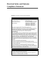
Electrical Safety and Emission
Compliance Statement
Standards: This product meets the following standards.
U.S. Federal Communications Commission
Declaration of Conformity
Manufacturer Name: Allied Telesyn, Inc.
Declares that the product: Fast Ethernet Media Converters
Model Numbers: AT-MC101XL, AT-MC102XL,
AT-MC103XL, AT-MC103LH,
AT-MC104XL, AT-MC104LH
This product complies with FCC Part 15B, Class B Limits:
This device complies with part 15 of the FCC Rules. Operation is subject to
the following two conditions: (1) This device must not cause harmful
interference, and (2) this device must accept any interference received,
including interference that may cause undesired operation.
Radiated Energy
Note: This equipment has been tested and found to comply with the limits for
a Class B digital device pursuant to Part 15 of FCC Rules. These limits are
designed to provide reasonable protection against harmful interference in a
residential installation. This equipment generates, uses and can radiate radio
frequency energy and, if not installed and used in accordance with
instructions, may cause harmful interference to radio or television reception,
which can be determined by turning the equipment off and on. The user is
encouraged to try to correct the interference by one or more of the following
measures:
- Reorient or relocate the receiving antenna.
- Increase the separation between the equipment and the receiver.
- Connect the equipment into an outlet on a circuit different from that to which
the receiver is connected.
- Consult the dealer or an experienced radio/TV technician for help.
Changes and modifications not expressly approved by the manufacturer or
registrant of this equipment can void your authority to operate this equipment
under Federal Communications Commission rules.
Industry Canada
This Class B digital apparatus meets all requirements of the Canadian
Interference-Causing Equipment Regulations.
Cet appareil numérique de la classe B respecte toutes les exigences du
Règlement sur le matériel brouilleur du Canada.

Electrical Safety and Emission Compliance Statement
iv
RFI Emissions FCC Part 15 Class B, EN55022 Class B,
CISPR 22 Class B, C-TICK
Immunity EN55024
Electrical Safety UL 60950-1 (
C
UL
US
), EN60950 (TUV),
CE
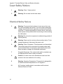
Laser Safety EN60825
Warning: Class 1 Laser product.
1
Warning: Do not stare into the Laser beam.
2
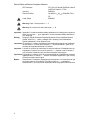
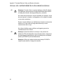
Important: Appendix C contains translated safety statements for installing this equipment.
When you see the , go to Appendix C for the translated safety statement in
your language.
Wichtig: Anhang C enthält übersetzte Sicherheitshinweise für die Installation dieses
Geräts. Wenn Sie sehen, schlagen Sie in Anhang C den übersetzten
Sicherheitshinweis in Ihrer Sprache nach.
Importante: El Apéndice C contiene mensajes de seguridad traducidos para la instalación
de este equipo. Cuando vea el símbolo , vaya al Apéndice C para ver el
mensaje de seguridad traducido a su idioma.
Important : L'annexe C contient les instructions de sécurité relatives à l'installation de cet
équipement. Lorsque vous voyez le symbole , reportez-vous à l'annexe C
pour consulter la traduction de ces instructions dans votre langue.
Importante: I’Appendice C contiene avvisi di sicurezza tradotti per l’installazione di questa
apparecchiatura. Il simbolo , indica di consultare l’Appendice C per l’avviso
di sicurezza nella propria lingua.
Важно: Приложение C содержит переведенную инструкцию по безопасности при
установке данного устройства. Если Вы встретите , перейдите к
Приложению C для получения переведенной инструкции по безопасности.

v
Contents
Electrical Safety and Emission Compliance Statement .................................iii
Preface ...............................................................................................................vii
How This Guide is Organized .............................................................................vii
Document Conventions......................................................................................viii
Where to Find Web-based Guides.......................................................................ix
Contacting Allied Telesyn..................................................................................... x
Online Support.............................................................................................. x
Email and Telephone Support ...................................................................... x
Returning Products ....................................................................................... x
Sales or Corporate Information..................................................................... x
Chapter 1
Overview ............................................................................................................. 1
Key Features........................................................................................................ 6
Status LEDs.................................................................................................. 6
Auto MDI/MDI-X............................................................................................ 7
Link Test (LINK TST)/MissingLinkTM (M/L) Button ...................................... 7
Link Test ....................................................................................................... 7
MissingLink ................................................................................................... 8
Auto-Negotiation Button................................................................................ 8
External AC/DC Power Adapter.................................................................. 10
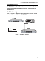
Network Topologies ........................................................................................... 11
Standalone Topology.................................................................................. 11
Back-to-Back Topology............................................................................... 12
Chapter 2
Installation ........................................................................................................ 13
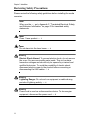
Reviewing Safety Precautions ........................................................................... 14
Selecting a Site for the Media Converter ........................................................... 16
Planning the Installation..................................................................................... 17
Unpacking the Media Converter......................................................................... 19

Contents
vi
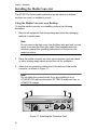
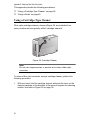
Installing the Media Converter ........................................................................... 20
Using the Media Converter on a Desktop................................................... 20
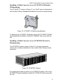
Installing a Media Converter in an AT-WLMT-010 Bracket Wallmounting.. 21
Installing a Media Converter in an AT-MCR12 Chassis for Rackmounting 21
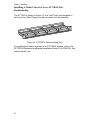
Installing a Media Converter in an AT-TRAY4 for Rackmounting............... 22
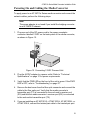
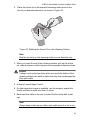
Powering On and Cabling the Media Converter................................................. 23
Warranty Registration ........................................................................................ 25
Chapter 3
Troubleshooting............................................................................................... 27
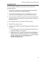
Loopback Test ................................................................................................... 29
Appendix A
Technical Specifications ................................................................................. 31
Physical.............................................................................................................. 31
Temperature....................................................................................................... 31
Electrical Rating ................................................................................................. 31
Agency Certifications ......................................................................................... 32
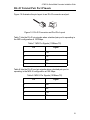
RJ-45 Twisted Pair Port Pinouts ........................................................................ 33
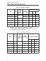
Fiber Optic Port Specifications........................................................................... 34
Appendix B
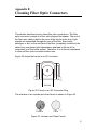
Cleaning Fiber Optic Connectors................................................................... 37
Using a Cartridge-Type Cleaner ........................................................................ 38
Using a Swab..................................................................................................... 40
Appendix C
Translated Electrical, Safety, and Emission Information ............................. 43

vii
Preface
This guide contains instructions on how to install an AT-MC10x Media
Converter.
How This Guide is Organized
This guide contains the following chapters and appendices:
Chapter 1, ”Overview” on page 1
Chapter 2, ”Installation” on page 13
Chapter 3, ”Troubleshooting” on page 27
Appendix A, ”Technical Specifications” on page 31
Appendix B, ”Cleaning Fiber Optic Connectors” on page 37
Appendix C, ”Translated Electrical, Safety, and Emission Information”
on page 43
This preface contains the following sections:
“Document Conventions” on page viii
“Where to Find Web-based Guides” on page ix
“Contacting Allied Telesyn” on page x

Preface
viii
Document Conventions
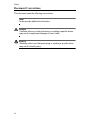
This document uses the following conventions:
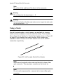
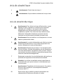
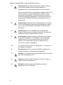
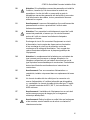
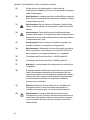
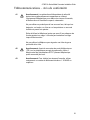
Note
Notes provide additional information.
Caution
Cautions inform you that performing or omitting a specific action
may result in equipment damage or loss of data.
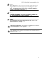
Warning
Warnings inform you that performing or omitting a specific action
may result in bodily injury.

AT-MC10x Series Media Converters Installation Guide
ix
Where to Find Web-based Guides
The installation and user guides for all Allied Telesyn products are
available in portable document format (PDF) on our web site at
www.alliedtelesyn.com. You can view the documents online or
download them onto a local workstation or server.

Preface
x
Contacting Allied Telesyn
This section provides Allied Telesyn contact information for technical
support as well as sales or corporate information.
Online Support
You can request technical support online by accessing the Allied Telesyn
Knowledge Base: www.alliedtelesyn.com/kb. You can use the
Knowledge Base to submit questions to our technical support staff and
review answers to previously asked questions.
Email and Telephone Support
For technical support via email or telephone, refer to the Support &
Services section of the Allied Telesyn web site: www.alliedtelesyn.com.
Returning Products
Products for return or repair must first be assigned a return materials
authorization (RMA) number. A product sent to Allied Telesyn without an
RMA number will be returned to the sender at the sender’s expense.
To obtain an RMA number, contact Allied Telesyn’s Technical Support
group through the Allied Telesyn web site: www.alliedtelesyn.com.
Sales or Corporate Information
You can contact Allied Telesyn for sales or corporate information on our
web site: www.alliedtelesyn.com. To find the contact information for
your country, select Contact Us -> Worldwide Contacts.

1
Chapter 1
Overview
The AT-MC10x Series Fast Ethernet Media Converters include the
following models:
AT-MC101XL
AT-MC102XL
AT-MC103XL
AT-MC103LH
AT-MC104XL
AT-MC104LH
The AT-MC10x Series Fast Ethernet Media Converters are designed to
extend the distance of your network by interconnecting LAN devices that
are physically separated by large distances.
The AT-MC101XL, AT-MC102XL, AT-MC103XL, and AT-MC103LH
media converters feature a 100Base-TX twisted pair port and an
100Base-FX fiber optic port. The twisted pair port has an RJ-45 connector
and a maximum operating distance of 100 meters (328 feet). The fiber
optic port has a dual ST or dual SC connector and a maximum operating
distance of 2 kilometers (1.2 miles) to 40 kilometers (24.8 miles),
depending on the model.
The AT-MC104XL and AT-MC104LH media converters feature two
100Base-FX fiber optic ports with either dual SC or dual ST connectors.
One port uses multi-mode fiber optic cabling and has a maximum
distance of 2 kilometers (1.2 miles). The second port uses single-mode
fiber optic cabling and has a maximum distance of 15 kilometers (9.3
miles) to 40 kilometers (24.8 miles), depending on the model.
These media converters operate at 100 Mbps and feature half- and full-
duplex operation.

Chapter 1: Overview
2
The AT-MC10x Series media converters can be installed on a desktop or
in an AT-MCR12 chassis, AT-WLMT-10 Wallmounting Bracket, or
AT-TRAY4 Rackmount Tray. The AT-MC10x Series media converters are
easy to install and do not require any software configuration or
management.
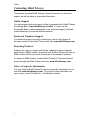
Figure 1 displays an AT-MC101XL Media Converter.
Figure 1. AT-MC101XL Model
Figure 2 displays an AT-MC102XL Media Converter.
Figure 2. AT-MC102XL Model
Figure 3 displays an AT-MC103XL Media Converter.
Figure 3. AT-MC103XL Model
744
AT-MC101XL
FAST ETHERNET MEDIA CONVERTER
LINK TST
M/L
ON
4
100Base-FX
LINK
ACT
100Base-TX
FDX
LINK
ACT M/L ON
PWR
TX RX
CLASS 1
LASER PRODUCT
A/N OFF
A/N ON
745
LINK TST
M/L
ON
4
100Base-FX
LINK
ACT
100Base-TX
FDX
LINK
ACT M/L ON
PWR
TX RX
CLASS 1
LASER PRODUCT
A/N OFF
A/N ON
AT-MC102XL
FAST ETHERNET MEDIA CONVERTER
747
LINK TST
M/L
ON
4
100Base-FX
LINK
ACT A/N OFF
A/N ON
100Base-TX
FDX
LINK
ACT M/L ON
PWR
TX RX
CLASS 1
LASER PRODUCT
AT-MC103XL SINGLE MODE FIBER FAST ETHERNET MEDIA CONVERTER

AT-MC10x Series Media Converters Installation Guide
3
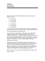
Figure 4 displays an AT-MC103LH Media Converter.
Figure 4. AT-MC103LH Model - Front Panel
Figure 5 displays an AT-MC104XL Media Converter.
Figure 5. AT-MC104XL Model - Front Panel
Figure 6 displays an AT-MC104LH Media Converter.
Figure 6. AT-MC104LH Model - Front Panel
746
LINK TST
M/L
ON
4
100Base-FX
LINK
ACT A/N OFF
A/N ON
100Base-TX
FDX
LINK
ACT M/L ON
PWR
TX RX
CLASS 1
LASER PRODUCT
AT-MC103LH
SINGLE MODE FIBER FAST ETHERNET MEDIA CONVERTER
LONG HAUL
749
LINK TST
M/L
ON
4
100Base-FX 100Base-FX
LINK
ACT
LINK
ACT M/L ON
PWR
TX RX
TX RX
CLASS 1
LASER PRODUCT
SINGLE MODE MULTI MODE
AT-MC104XL
SINGLE MODE /MULTI MODE FIBER FAST ETHERNET MEDIA CONVERTER
748
LINK TST
M/L
ON
4
100Base-FX 100Base-FX
LINK
ACT
LINK
ACT M/L ON
PWR
TX RX
TX RX
CLASS 1
LASER PRODUCT
AT-MC104LH
SINGLE MODE /MULTI MODE FIBER FAST ETHERNET MEDIA CONVERTER
LONG HAUL
SINGLE MODE MULTI MODE

Chapter 1: Overview
4
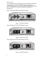
Figure 7 displays an AT-MC103LH Media Converter.
Figure 7. AT-MC10x Series - Rear Panel
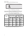
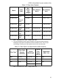
Table 1 lists the maximum operating distances for the AT-MC101XL,
AT-MC102XL, AT-MC103XL, and AT-MC103LH media converters.
1. Maximum distance may be less depending on the duplex mode of the end
stations and the type of fiber optic cabling used with the port.
Table 1. Maximum Operating Distances
(AT-MC101XL, AT-MC102XL, AT-MC103XL, and AT-MC103LH)
Model
Type of Connector
Maximum Operating
Distance
1
100Base-
FX
100Base-
TX
100Base-
FX
100Base-
TX
AT-MC101XL Dual ST RJ-45 2 km
(1.2 mi)
100 m
(328 ft)
AT-MC102XL Dual SC RJ-45 2 km
(1.2 mi)
100 m
(328 ft)
AT-MC103XL Dual SC RJ-45 15 km
(9.3 mi)
100 m
(328 ft)
AT-MC103LH Dual SC RJ-45 40 km
(24.8 mi)
100 m
(328 ft)
12VDC
310

AT-MC10x Series Media Converters Installation Guide
5
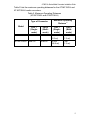
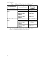
Table 2 lists the maximum operating distances for the AT-MC104XL and
AT-MC104LH media converters.
Table 2. Maximum Operating Distances
(AT-MC104XL and AT-MC104LH)
Model
Type of Connector
Maximum Operating
Distance
1
Port 1
(Single-
mode)
Port 2
(Multi-
mode)
Port 1
(Single-
mode)
Port 2
(Multi-
mode)
AT-MC104XL Dual SC Dual SC 15 km
(9.3 mi)
2 km
(1.2 mi)
AT-MC104LH Dual SC Dual SC 40 km
(24.8 mi)
2 km
(1.2 mi)

Chapter 1: Overview
6
Key Features
The media converters have the following key features:
LEDs for unit and port status
100Base-TX twisted pair port (all models except AT-MC104xx Series)
100Base-FX fiber optic port(s)
Auto MDI-MDI/X
Half- or full-duplex operation with Auto-Negotiation function
Link Test/MissingLink
TM
button for performing a link test or activating
the MissingLink feature which notifies end-nodes of connection
failures
External AC/DC power adapter
Standard size for use in an AT-MCR12 chassis, AT-WLMT-10 bracket,
or AT-TRAY4 tray
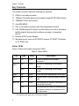
Status LEDs
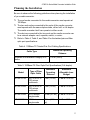
Figure 3 defines the media converter’s LEDs.
1 This LED does not apply to the AT-MC104xx models.
Table 3. Status LEDs
LED State Color Description
PWR ON Green Power is applied to the media
converter.
FDX
1
ON Green The port is operating in full-duplex
mode.
OFF The port is operating in half-duplex
mode.
LINK ON Green A link has been established on the port.
ACT ON Green Network traffic is being received on the
port.
M/L ON ON Green The MissingLink feature is activated on
the media converter.
OFF The MissingLink feature is disabled and
the media converter is operating in the
link test mode.

AT-MC10x Series Media Converters Installation Guide
7
Auto MDI/MDI-X
An RJ-45 twisted pair port on an 100 Mbps Ethernet network device can
have one of two possible wiring configurations: MDI or MDI-X. The RJ-45
port on a PC, router, or bridge is typically wired as MDI, while the twisted
pair port on a switch or hub is usually MDI-X.
The AT-MC10x Series media converters feature automatic MDI/MDI-X.
The 100Base-TX port automatically determines the configuration of the
port on the device to which it is connected and then configures itself
appropriately. For example, if a port on a media converter is connected to
a port on a bridge, which is typically wired as MDI, the port on the media
converter automatically configures itself as MDI-X. This feature allows
you to use a straight-through cable when connecting any type of device to
the media converter.
Link Test (LINK TST)/MissingLink
TM
(M/L) Button
The LINK TST/M/L button allows you to perform a link test on the ports on
the media converter. This button also allows you to activate the
MissingLink feature on the unit. Both features are describe in the
following section.
Link Test
The link test is a fast and easy way for you to test the connections
between the ports on the media converter and the nodes that are
connected to the ports. If a network problem occurs, you can perform a
link test to determine which port is experiencing a problem, and be able to
focus on the port and end-node where the problem resides.
A link test is performed when the button is in the LINK TST (OUT)
position. For instructions on performing a link test, refer to
“Troubleshooting” on page 33.
Note
Leaving the media converter in the LINK TST (OUT) position will
not interfere with the units ability to pass network traffic.

Chapter 1: Overview
8
MissingLink
The MissingLink feature enables the fiber optic ports on the media
converter to pass the “Link” status of their connections to each other.
When the media converter detects a problem with one of the ports, such
as the loss of connection to an end-node, the media converter shuts down
the connection to the other port, thus notifying the node that the
connection has been lost.
For example, if the twisted pair cable to the 100Base-TX port on the
media converter were to fail, the media converter would respond by
dropping the link on the 100Base-FX fiber optic port. In this way, the
media converter notifies the end-node connected to the fiber optic port
that the connection on the twisted pair port has been lost. If the failure had
started with the fiber optic cabling, the unit would drop the link to the
twisted pair port.
The value to this type of network monitoring and fault notification is that
some hubs and switches can be configured to take a specific action in the
event of the loss of connection on a port. In some cases, the unit can be
configured to seek a redundant path to a disconnected node or send out a
trap to a network management station, and so alert the network
administrator of the problem.
Note
The MissingLink feature is disabled when you perform a link test
with the Link Test/MissingLink button. Consequently, to ensure that
the MissingLink feature is activated on the media converter, always
set the button to the M/L ON (IN) position during normal network
operations.
Auto-Negotiation Button
The Auto-Negotiation (A/N) button, located on the front panel of the
AT-MC101XL, AT-MC102XL, and AT-MC103XL/LH, enables and
disables the Auto-Negotiation feature (IEEE 802.3u) of the media
converter. The media converter uses Auto-Negotiation to determine the
duplex mode of the ports. The duplex mode refers to the manner in which
an end-node sends and receives data on the network. An end-node can
operate in either half- or full-duplex mode. A node operating in half-duplex
can either send or receive data, but not both at the same time. An end-
node operating in full-duplex can send and receive data simultaneously.
The best network performance is achieved when an end-node can
operate in full-duplex mode.

AT-MC10x Series Media Converters Installation Guide
9
In most configurations, you will want to leave the Auto-Negotiation button
activated so the unit can determine the appropriate duplex mode, based
on the capabilities of the end-nodes. For example, the Auto-Negotiation
feature on the media converter should be left activated in situations where
both end-nodes are also capable of Auto-Negotiation, or where both end-
nodes have been pre-set to the same mode or are capable of operating in
only one duplex mode, such as half-duplex.
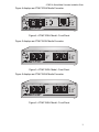
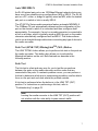
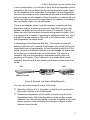
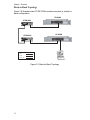
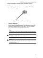
There is one situation where it may be necessary to disable the Auto-
Negotiation feature, and that is to prevent a mismatch from occurring
between the duplex modes of the end-nodes. For example, Figure 8
shows two units that have been connected with a media converter. Unit 1
is a repeater that is capable of operating in half-duplex mode only. Unit 2
is a switch that can operate in either half- or full-duplex mode, and will
Auto-Negotiation the duplex mode.
In attempting to Auto-Negotiate with Unit 1, the media converter will
determine that the unit is capable of half-duplex only and will set the port
connected to the unit appropriately. In Auto-Negotiating with Unit 2, the
media converter will determine that the unit can manage full-duplex and
will set the port connected to the unit to full-duplex. The result is a
mismatch, with one unit operating in half-duplex and the other unit
operating in full-duplex. This is referred to as a classic duplex mode
mismatch and will result in poor network performance between the end-
nodes.
Figure 8. Example of a Duplex Mode Mismatch
You can resolve the mismatch in one of two ways:
Manually configure Unit 2, if possible, so that the port connected to
the media converter is set to half-duplex.
Disable Auto-Negotiation on the media converter using the Auto-
Negotiation button. With Auto-Negotiation on the media converter
disabled, Unit 2 will assume that the converter is capable of only half-
duplex operation, thus eliminating the mismatch in duplex modes
between the end-nodes.
LINK TST
M/L
ON
4
100Base-FX
LINK
ACT A/N OFF
A/N ON
100Base-TX
FDX
LINK
ACT M/L O N
PWR
TX RX
CLASS 1
LASER PRODUCT
AT-MC103XL SINGLE MODE FIBER FAST ETHERNET MEDIA CONVERTER
750
Unit 1 Unit 2
100Base-FX Repeater
Media Converter
100Base-TX Switch

Chapter 1: Overview
10
Note
After a configuration change, you must reset the media converter
by powering OFF then powering ON the unit
On the AT-MC101XL, AT-MC102XL, AT-MC103XL, and
AT-MC103LH models, set the Auto-Negotiation feature as follows:
If both end-nodes will use Auto-Negotiation to determine the
duplex mode, or if both are pre-set to operate with the same
duplex mode, such as half-duplex, set the switch to the A/N ON
(IN) position. This is the default setting.
If one end-node is capable of operating at only half-duplex mode
while the other node will determine its duplex mode through Auto-
Negotiation, set the switch to the A/N OFF (OUT) position.
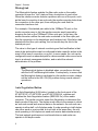
External AC/DC Power Adapter
An external AC/DC power adapter is included with the media converter
for standalone operation. The power adapter supplies 12V DC to the
media converter. Allied Telesyn supplies an approved safety compliant
AC power adapter for the 120 and 240V AC versions with an unregulated
output of 12V DC at 1 A. The power required for the media converter is
12V DC, 500 mA.
La page est en cours de chargement...
La page est en cours de chargement...
La page est en cours de chargement...
La page est en cours de chargement...
La page est en cours de chargement...
La page est en cours de chargement...
La page est en cours de chargement...
La page est en cours de chargement...
La page est en cours de chargement...
La page est en cours de chargement...
La page est en cours de chargement...
La page est en cours de chargement...
La page est en cours de chargement...
La page est en cours de chargement...
La page est en cours de chargement...
La page est en cours de chargement...
La page est en cours de chargement...
La page est en cours de chargement...
La page est en cours de chargement...
La page est en cours de chargement...
La page est en cours de chargement...
La page est en cours de chargement...
La page est en cours de chargement...
La page est en cours de chargement...
La page est en cours de chargement...
La page est en cours de chargement...
La page est en cours de chargement...
La page est en cours de chargement...
La page est en cours de chargement...
La page est en cours de chargement...
La page est en cours de chargement...
La page est en cours de chargement...
La page est en cours de chargement...
La page est en cours de chargement...
La page est en cours de chargement...
La page est en cours de chargement...
La page est en cours de chargement...
La page est en cours de chargement...
La page est en cours de chargement...
La page est en cours de chargement...
La page est en cours de chargement...
La page est en cours de chargement...
La page est en cours de chargement...
La page est en cours de chargement...
La page est en cours de chargement...
La page est en cours de chargement...
La page est en cours de chargement...
La page est en cours de chargement...
La page est en cours de chargement...
La page est en cours de chargement...
La page est en cours de chargement...
La page est en cours de chargement...
La page est en cours de chargement...
La page est en cours de chargement...
La page est en cours de chargement...
La page est en cours de chargement...
La page est en cours de chargement...
La page est en cours de chargement...
La page est en cours de chargement...
La page est en cours de chargement...
La page est en cours de chargement...
La page est en cours de chargement...
La page est en cours de chargement...
La page est en cours de chargement...
-
 1
1
-
 2
2
-
 3
3
-
 4
4
-
 5
5
-
 6
6
-
 7
7
-
 8
8
-
 9
9
-
 10
10
-
 11
11
-
 12
12
-
 13
13
-
 14
14
-
 15
15
-
 16
16
-
 17
17
-
 18
18
-
 19
19
-
 20
20
-
 21
21
-
 22
22
-
 23
23
-
 24
24
-
 25
25
-
 26
26
-
 27
27
-
 28
28
-
 29
29
-
 30
30
-
 31
31
-
 32
32
-
 33
33
-
 34
34
-
 35
35
-
 36
36
-
 37
37
-
 38
38
-
 39
39
-
 40
40
-
 41
41
-
 42
42
-
 43
43
-
 44
44
-
 45
45
-
 46
46
-
 47
47
-
 48
48
-
 49
49
-
 50
50
-
 51
51
-
 52
52
-
 53
53
-
 54
54
-
 55
55
-
 56
56
-
 57
57
-
 58
58
-
 59
59
-
 60
60
-
 61
61
-
 62
62
-
 63
63
-
 64
64
-
 65
65
-
 66
66
-
 67
67
-
 68
68
-
 69
69
-
 70
70
-
 71
71
-
 72
72
-
 73
73
-
 74
74
-
 75
75
-
 76
76
-
 77
77
-
 78
78
-
 79
79
-
 80
80
-
 81
81
-
 82
82
-
 83
83
-
 84
84


Allied Telesis AT-MC104LH Guide d'installation
- Catégorie
- Convertisseurs de média réseau
- Taper
- Guide d'installation
- Ce manuel convient également à
dans d''autres langues
Documents connexes
Autres documents
-
 Davis Instruments #6810 Troubleshooting guide
-
 IMC Networks iMcV-S2SM/1250 Manuel utilisateur
-
Transition Networks E-100BTX-FX-05(100) Manuel utilisateur
-
LG-Ericsson ipecs ES-5048XG Guide d'installation
-
Transition Networks Switch CERTXFX01(SM) Manuel utilisateur
-
-
SMC Networks SMCGS26C-Smart Manuel utilisateur
-
Korenix JetCon 1501 Series Quick Installation Manual
-
-
 Davis Instruments 6800 Troubleshooting guide


