
Owner's Manual
Hand-Held Bidet Holster
with Integrated Shut O
BIDET SPRAYER ACCESSORY
MODELS MBH10/MBH37/MBH40

2
Table of Contents
MBH10/MBH37/MBH40 OWNER'S MANUAL
This manual contains important safety information.
Before operating your Hand-Held Bidet Holster with
Integrated Shut O, please read this manual thoroughly
and retain it for future reference.
01
01
02
03
PRODUCT INFORMATION
Product Features
Product Dimensions
Product Parts
04
04
05
PRODUCT INSTALLATION
Before Installation
Installation
07
07
PRODUCT OPERATION
Using the Hand-Held Bidet Holster
with Integrated Shut O
08 MAINTENANCE
09 PRODUCT SPECIFICATIONS
10 WARRANTY
11 CONTACT
01 ENGLISH
12 SPANISH
24 FRENCH
GENERAL INFORMATION
PRODUCT INSTALLATION
PRODUCT OPERATION
TRANSLATIONS
TECHNICAL INFORMATION

1
Polished Stainless Steel Hand-Held Bidet
Sprayer Mount
Integrated Chrome Water Shut O Handle
Universal Hand-Held Sprayer Holster Works
With Any Sprayer
High-Quality Metal ⅞" T-Valve
Durable Braided Metal Cold Water Hose
No Electricity Or Batteries Required
Easy Installation And Adjustable Toilet Fit
One-Year Warranty
Product Features
PRODUCT INFORMATION

2
Product Dimensions
PRODUCT INFORMATION
2.24 in 1.97 in
15.75 in
11.81 in
3.15 in
0.08 in thick
0.45 in

3
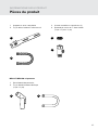
Product Parts
PRODUCT INFORMATION
1. Stainless Steel Mount
2. Cold Water Braided Metal Hose
1. Sprayer Head
2. Metal Sprayer Hose (½" X ½")
3. Large Rubber Washer (1)
4. Cold Water T-Valve Connector
(⅞" x ⅞" x ⅜")
1
1
2
2
3
4
MBH-37/MBH-40 Only

4
You must have a CleanSpa hand-held bidet or
equivalent product with a ½" connection sprayer hose
in order to install the Hand-Held Bidet Holster with
Integrated Shut O.
IMPORTANT
Please be advised that the provided cold water T-valve
should be installed at the fill valve under the toilet tank,
NOT at the cold water supply coming from the wall.
Check Water Supply Line
If the pipe that connects the toilet tank fill valve to the
water shuto valve at the wall is rigid, you will need
to purchase a flexible water supply hose to replace
it before installing the Hand-Held Bidet Holster with
Integrated Shut O. The length of the hose may vary
and the top connection size should be ⅞" ballcock to
connect to the T-valve that you will install under the
toilet tank and the bottom connection will vary (most
common are ⅜" and ½” female compression).
Before Installation
PRODUCT INSTALLATION
INCORRECT
Cold Water Supply
Fill Valve
CORRECT

5
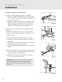
Installation
PRODUCT INSTALLATION
Please read these instructions carefully before installing
your Hand-Held Bidet Holster with Integrated Shut
O. Failure to do so could result in flooding, leaking or
damage to the product.
1. Existing Toilet Seat Removal
a. Lift hinge covers and use flathead or Phillips
head screwdriver to remove the mounting bolts.
Alternatively, you may need to loosen mounting
bolts underneath the seat.
b. Remove the toilet seat and set the seat, mounting
bolts and hardware aside.
2. Turn O Water Supply Valve and Flush Toilet
a. Turn water supply valve o to stop the flow of water.
b. Flush toilet and hold down handle to completely
empty tank.
c. Disconnect water supply hose from toilet tank.
Do not disconnect from the water supply valve.
d. If you have a hand-held bidet sprayer already
connected to your toilet tank, remove the existing
T-valve and hand-held bidet sprayer connection
hose.
3. Connect Cold Water T-Valve to the Toilet Tank Fill Valve
a. Install the included ⅞" cold water T-valve with the
large rubber washer provided to the incoming water
connection on the bottom of your toilet tank.
b. Connect the cold water supply line coming from the
wall to the bottom of the T-valve.
4. Connect Cold Water Hose to T-Valve
Connect one end of the Cold Water Braided Metal
Hose to the remaining open side of the installed
T-valve.
Step 3a
Step 3b
Step 1b
Step 2c
Step 4

6
Installation
PRODUCT INSTALLATION
Installing the Hand-Held Bidet Holster
1. Install Hand-Held Bidet Holster on Toilet
a. Place Hand-Held Bidet Holster on the toilet so the
mounting slots line up with the holes in the toilet
fixture.
b. Replace the toilet seat on top of Hand-Held Bidet
Holster and secure using original toilet seat
hardware. Make sure to tighten so that the holster
and seat do not move.
2. Connect Cold Water Hose to Hand-Held Bidet Holster
Attach the open end of the Cold Water Braided Metal
Bidet Hose to the incoming water connection on the
side of the holster.
3. Connect Hand-Held Bidet Sprayer to Holster
a. Connect your hand-held bidet sprayer to the
sprayer hose.
b. Connect the open end of the sprayer hose to the ½"
connection at the bottom of the holster.
c. Place the hand-held bidet sprayer in the holster slot.
4. Turn on Water Supply & Check for Leaks
a. Open the main water supply valve slowly and check
for leaks.
b. Wait 5-10 minutes, check again, and if there are no
leaks, continue.
Step 1a
Step 1b
Step 2
Step 3b
NOTE: If there is any leaking, check all rubber washers
and make sure all water connections are tight and
secure. If necessary, you can use plumbers tape for any
leaking connections.

7
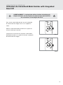
Using the Hand-Held Bidet Holster with Integrated Shut O
PRODUCT OPERATION
To engage your hand-held bidet, turn on the
integrated shut o faucet handle located on the
metal holster.
Remove the sprayer from the holster and use in
normal fashion.
When finished, replace the sprayer in the holster
and turn o the integrated shut o faucet handle.
WARNING: The faucet handle must be turned o after each use.
Failure to turn o after each use may cause flooding and water damage.
On
O

8
Maintenance
TECHNICAL INFORMATION
To clean the Hand-Held Bidet Holster with
Integrated Shut O, use a mild cleaner such as
Simple Green or Windex spray. Do not scrub
or use harsh, abrasive products to clean the
Hand-Held Bidet Holster with Integrated Shut
O, which may scratch the product.
Short Term Non-Use
If the product will not be used for more than
a few weeks, you may consider shutting the
water supply o at the wall as an additional
precaution.

9
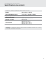
NOTE: The specifications listed above are subject to change without prior notice for reasons of improving
the product performance.
HANDHELD BIDET HOLSTER WITH INTEGRATED SHUT OFF
Models MBH10, MBH37, MBH40
Supply Water Pressure 20 psi–100 psi / 0.14 MPa–0.69 MPa
Incoming Water Temperature Range 32 °F–158 °F / 0 °C–70 °C
Product Dimension 15.75 in x 2.24 in / 40 cm x 6 cm
Product Thickness 0.08 in / 0.2 cm
Product Weight
MBH10: 1.14 lb / 0.7 kg
MBH37: 2.23 lb / 1.02 kg
MBH40: 2.29 lb / 1.04 kg
TECHNICAL INFORMATION
Product Specifications

10
Warranty
TECHNICAL INFORMATION
Brondell products are backed by some of the most comprehensive warranties in the industry. Brondell
warrants that all products (excluding consumable items) shall be free from defects in material and
workmanship under normal use and service.
MBH-10/MBH-37/MBH-40 RESIDENTIAL ONE-YEAR LIMITED WARRANTY
100% Coverage of all parts and labor for the entire product for the first year from original date of purchase.
MBH-10/MBH-37/MBH-40 COMMERCIAL WARRANTY
Warranty period 1 year from original purchase date for all Brondell products. Warranties may not apply to
products that are used for heavy commercial, hospital, or other high use non-residential applications.
EXCLUSIONS AND LIMITATIONS
1. Brondell warrants its products to be free from manufacturing defects under normal use and service. This
warranty is extended only to the ORIGINAL PURCHASER.
2. Brondell’s obligations under this warranty are limited to repairs or replacement, at Brondell’s option, of
products or parts found to be defective, provided that such products were properly installed and used in
accordance with instructions. Brondell reserves the right to make such inspections as may be necessary
in order to determine the cause of the defect.
3. Brondell is not responsible for the cost of removal, return (shipping) and/or re-installation of products.
This warranty does NOT apply to:
• Damage or loss which occurs during shipment.
• Damage or loss sustained through any natural or man-made causes beyond the control of
Brondell, including but not limited to fire, earthquake, floods, etc.
• Damage or loss resulting from sediments or foreign matter contained in a water system.
• Damage or loss resulting from negligent or improper installation including installation of a unit in a
harsh or hazardous environment.
• Damage or loss resulting from removal, improper repair, modification of the product, or improper
maintenance including damage caused by chlorine or chlorine related products.
4. This warranty gives you specific legal rights. You may have other rights which vary from state to state.
THIS WRITTEN WARRANTY IS THE ONLY WARRANTY MADE BY BRONDELL. REPAIR OR REPLACEMENT
AS PROVIDED UNDER THIS WARRANTY SHALL BE THE EXCLUSIVE REMEDY AVAILABLE TO THE
PURCHASER. BRONDELL SHALL NOT BE RESPONSIBLE FOR LOSS OF USE OF THE PRODUCT OR FOR
OTHER INCIDENTAL, SPECIAL, FOR CONSEQUENTIAL DAMAGES OR EXPENSES INCURRED BY THE
PURCHASER OR FOR LABOR OR OTHER COSTS DUE TO INSTALLATION OR REMOVAL OR COSTS OF
REPAIRS BY OTHERS, OR FOR ANY OTHER EXPENSE NOT SPECIFICALLY STATED ABOVE. EXCEPT
TO THE EXTENT PROHIBITED BY APPLICABLE LAW, ANY IMPLIED WARRANTIES, INCLUDING THAT OF
MERCHANTABILITY, ARE EXPRESSLY LIMITED TO THE DURATION OF THIS WARRANTY. SOME STATES
DO NOT ALLOW LIMITATIONS, SO THE ABOVE LIMITATION AND EXCLUSION MAY NOT APPLY TO YOU.
HOW TO OBTAIN SERVICE
To obtain repair service under this warranty, you must contact an authorized Brondell Service Center to
obtain an RMA (Return Merchandise Authorization) number. Proof of purchase in the form of a copy of the
original receipt must accompany the returned unit for the warranty to be valid. Take or ship the unit pre-
paid to the closest Brondell authorized service center along with the RMA number and proof of purchase.
To obtain the RMA number and locate the Brondell Service Center location nearest you, please call 1-888-
542-3355, Mon–Fri, 9am–5pm PST.

11
CONTACT:
Brondell, Inc.
PO Box 470085
San Francisco, CA 94147-0085
Email: [email protected]
Web: www.brondell.com
For questions, contact
Brondell Customer Service:
1-888-542-3355
Monday – Friday
9am – 5pm PST
MANUFACTURED BY:
Brondell, Inc.
PO Box 470085
San Francisco, CA 94147-0085
Made in China
Please retain receipt records for any
warranty claims.

12
Indices
MANUAL DE INSTRUCCIONES DEL MBH10/MBH37/MBH40
Este manual contiene información de seguridad
importante. Lea este manual atentamente antes de
utilizar su Hand-Held Bidet Holster with Integrated Shut
O y guárdelo para futuras consultas.
13
13
14
15
INFORMACIÓN DEL PRODUCTO
Características del producto
Dimensiones del producto
Piezas del producto
16
16
17
INSTALACIÓN DEL PRODUCTO
Antes de la instalación
Instalación
19
19
FUNCIONAMIENTO DEL PRODUCTO
Uso de Hand-Held Bidet Holster with
Integrated Shut O
20 MANTENIMIENTO
21 ESPECIFICACIONES DEL PRODUCTO
22 GARANTÍA
23 CONTACTO
01 INGLÉS
24 FRANCÉS
INFORMACIÓN GENERAL
INSTALACIÓN DEL PRODUCTO
FUNCIONAMIENTO DEL
PRODUCTO
TRADUCCIONES
INFORMACIÓN TÉCNICA

13
Montaje para rociador de bidé manual de acero
inoxidable pulido
Mango cromado e integrado de cierre de agua
La funda universal para el rociador de mano funciona
con cualquier rociador
Válvula en T de ⅞" de metal de alta calidad
Manguera de agua fría de metal trenzado resistente
No se necesita suministro de electricidad ni baterías
Instalación sencilla y ajuste adaptable al inodoro
Garantía de un año
Características del producto
INFORMACIÓN DEL PRODUCTO

14
Dimensiones del producto
INFORMACIÓN DEL PRODUCTO
5,69cm 5cm
40cm
30cm
8cm
0,20cm de ancho
1,14cm

15
Piezas del producto
INFORMACIÓN DEL PRODUCTO
1. Montaje de acero inoxidable
2. Manguera de agua fría de metal trenzado
1. Cabeza del rociador del bidé
2. Manguera rociadora de metal (½" x ½")
3. Arandela grande de goma (1)
4. Conector de agua fría de válvula en T
(⅞" x ⅞" x ⅜")
1
1
2
2
3
4
Solo para el MBH-37/MBH-40

16
Debe tener un bidé manual CleanSpa o un producto
equivalente con una manguera rociadora de conexión de
½" para instalar Hand-Held Bidet Holster with Integrated
Shut O.
IMPORTANTE
Tenga en cuenta que la válvula en T para agua fría
provista se debe instalar en la válvula de llenado debajo
del tanque del inodoro, NO en la entrada del suministro
de agua fría que sale de la pared.
Revisar la línea de suministro de agua
Si la tubería que conecta la válvula de llenado del tanque
del inodoro con la válvula de corte en la pared es rígida,
deberá comprar una manguera flexible de suministro
de agua para reemplazarla antes de instalar Hand-
Held Bidet Holster with Integrated Shut O. El largo de
la manguera puede variar y el tamaño de la conexión
superior debe ser para una válvula de flotador de ⅞"
para conectarla a la válvula en T que instalará debajo del
tanque del inodoro; la conexión inferior variará (las más
comunes son de compresión hembra de ⅜" y ½").
Antes de la instalación
INSTALACIÓN DEL PRODUCTO
INCORRECTO
Suministro de
agua fría
Llenar la
válvula
CORRECTO

17
Instalación
INSTALACIÓN DEL PRODUCTO
Lea atentamente estas instrucciones antes de instalar su
Hand-Held Bidet Holster with Integrated Shut O. De lo
contrario, podrían surgir problemas, como acumulación
de agua, fugas o daños al producto.
1. Cómo retirar el asiento del inodoro existente
a. Levante las tapas de las bisagras y use un
destornillador de cabeza plana o Phillips para quitar
los pernos de montaje. De manera alternativa, es
posible que deba aflojar los pernos de montaje que
se encuentran debajo del asiento.
b. Retire el asiento del inodoro y déjelo a un lado,
junto con los pernos y las herramientas.
2. Cierre la válvula de suministro de agua y descargue el
inodoro.
a. Cierre la válvula de suministro de agua para
detener el flujo de agua.
b. Descargue el inodoro y mantenga la manija
presionada para que el tanque se vacíe por
completo.
c. Desconecte la manguera del suministro de agua del
tanque del inodoro.No la desconecte de la válvula
de suministro de agua.
d. Si ya tiene un rociador de bidé manual conectado al
tanque del inodoro, retire la válvula en T existente
y la manguera de conexión del rociador de bidé
manual.
3. Conecte la válvula en T de agua fría a la válvula de
llenado del tanque del inodoro
a. Instale la válvula en T de ⅞" de la entrada de
agua fría incluida con la arandela de goma grande
incluida en la conexión de agua entrante en la parte
inferior del tanque del inodoro.
b. Conecte la línea de suministro de agua fría que
viene de la pared a la parte inferior de la válvula T.
4. Conecte la manguera de agua fría a la válvula en T
Conecte un extremo de la manguera de metal
trenzado para agua fría al extremo libre de la válvula
en T instalada.
Paso 3a
Paso 3b
Paso 1b
Paso 2c
Paso 4

18
Instalación
INSTALACIÓN DEL PRODUCTO
Instalación de la funda de bidé manual
1. Instale la funda de bidé manual en el inodoro
a. Coloque la funda de bidé manual en el inodoro de
modo que las ranuras de montaje queden alineadas
con los orificios del accesorio del inodoro.
b. Vuelva a colocar el asiento del inodoro en la parte
superior de la funda de bidé manual y asegúrelo
con los materiales originales del asiento del inodoro.
Asegúrese de ajustarlos para que la funda y el
asiento no se muevan.
2. Conecte la manguera de agua fría a la funda de bidé
manual
Conecte el extremo libre de la manguera de bidé de
metal trenzado de agua fría a la conexión de agua
entrante en el lateral de la funda.
3. Conecte el rociador de bidé manual a la funda
a. Conecte el rociador de bidé manual a la manguera
rociadora.
b. Conecte el extremo libre de la manguera rociadora a
la conexión de ½" en la parte inferior de la funda.
c. Coloque el rociador de bidé manual en la abertura
de la funda.
4. Encienda el suministro de agua y verifique si hay fugas
a. Abra lentamente la válvula principal de suministro de
agua y compruebe si hay fugas.
b. Espere de 5 a 10 minutos, vuelva a verificar y, si no
hay fugas, continúe.
Paso 1a
Paso 1b
Paso 2
Paso 3b
NOTA: Si hay alguna fuga, revise todas las arandelas de
goma y asegúrese de que todas las conexiones de agua
estén ajustadas y seguras. Si es necesario, puede usar
cinta de teflón para las conexiones con fugas.
La page charge ...
La page charge ...
La page charge ...
La page charge ...
La page charge ...
La page charge ...
La page charge ...
La page charge ...
La page charge ...
La page charge ...
La page charge ...
La page charge ...
La page charge ...
La page charge ...
La page charge ...
La page charge ...
La page charge ...
La page charge ...
La page charge ...
La page charge ...
-
 1
1
-
 2
2
-
 3
3
-
 4
4
-
 5
5
-
 6
6
-
 7
7
-
 8
8
-
 9
9
-
 10
10
-
 11
11
-
 12
12
-
 13
13
-
 14
14
-
 15
15
-
 16
16
-
 17
17
-
 18
18
-
 19
19
-
 20
20
-
 21
21
-
 22
22
-
 23
23
-
 24
24
-
 25
25
-
 26
26
-
 27
27
-
 28
28
-
 29
29
-
 30
30
-
 31
31
-
 32
32
-
 33
33
-
 34
34
-
 35
35
-
 36
36
-
 37
37
-
 38
38
-
 39
39
-
 40
40


brondell MBH-37-S Le manuel du propriétaire
- Taper
- Le manuel du propriétaire
- Ce manuel convient également à
dans d''autres langues
- English: brondell MBH-37-S Owner's manual
- español: brondell MBH-37-S El manual del propietario
Documents connexes
-
brondell CSL 40 Clean Spa Luxury Handheld Bidet Spray Le manuel du propriétaire
-
-
-
-
brondell S1400-RW Manuel utilisateur
-
-
-
brondell LES512 Le manuel du propriétaire
-
brondell CSG15-RW Le manuel du propriétaire
-