
START 28 KI
START 24-28-35 KIS
EN - INSTALLER AND USER MANUAL
FR - MANUEL D’INSTALLATION ET D’UTILISATION
UA - GE КЕРІВНИЦТВО З УСТАНОВКИ ТА ЕКСПЛУАТАЦІЇ

START KI - KIS
2
Installer’s - User’s manual ..................................... 3-14
Boiler operating elements ...................................... 56
Hydraulic circuit ..................................................... 58
Electric diagrams ................................................... 60
Circulator residual head......................................... 63
The following symbols are used in this manual:
CAUTION = operations requiring special care and
adequate preparation
NOT ALLOWED = operations that MUST NOT be
performed
START boiler complies with basic requirements of the
following Directives:
- Gas directive 2009/142/EC;
- Efficiency directive: Article 7(2) and Annex III of directive
92/42/EEC;
- Electromagnetic compatibility directive 2014/30/EU;
- Low-voltage directive 2014/35/EU.
EN
Manuel d’installation - Manuel de l’utilisateur ........ 20-32
Éléments fonctionnels de la chaudière .................. 56
Circuit hydraulique ................................................. 58
Schémas électriques ............................................. 60
Prévalence résiduelle du circulateur...................... 63
Керівництво з установки та експлуатації ............ 38-50
Функціональні елементи котла............................ 56
Гідравлічна схема ................................................ 58
Електричні схеми ................................................. 60
Висота нагнітання циркуляційного насосу ......... 63
Dans certaines parties du manuel on utilise les symboles:
ATTENTION = actions demandant une certaine
prudence et une préparation adéquate
INTERDICTION = actions NE DEVANT absolument PAS
être exécutées
В даному керівництві використовуються наступні символи:
УВАГА = дії, що потребують підвищеної уваги та
відповідної підготовки
ЗАБОРОНЕНО = дії, які НЕ МОЖНА ВИКОНУВАТИ ні
в якому разі
La chaudière START respecte les conditions de base
requises par les Règlements suivants:
- Directive sur le gaz 2009/142/CEE;
- Directive sur le rendement: Article 7(2) et Annexe III de la
directive 92/42/CEE;
- Directive sur la compatibilité électromagnétique 2014/30/
EU;
- Directive sur la basse tension 2014/35/EU.
Котел START відповідає основним вимогам наступних
Директив:
- Газова директива 2009/142/EC;
- Директива з питань ефективності: Розділ 7(2) та
Додаток III директиви 92/42/EEC;
- Директива з електромагнітної сумісності 2014/30/EU;
- Директива ЄС з низьковольтного електротехнічного
обладнання 2014/35/EU.
FR
UK

ENGLISH
3
EN ENGLISH
INSTALLER MANUAL
1 - WARNINGS AND SAFETY INSTRUCTIONS
After removing the packaging, make sure that the product is
integral and complete with all its parts. If it does not correspond
with the order made, please contact the Riello Agency that sold
the boiler.
The boiler must be installed by a qualified company in
accordance with the regulations in force and in observance of
applicable legislation and of the indications provided by Riello
in the present instructions booklet.
The installer explains how the appliance operates to the user,
and the basic safety regulations.
The boiler must be used for the purpose envisaged by the
producer, for which it was expressly made. No contractual
or extracontractual liability is accepted by Riello for damage
caused to people, animals, or objects due to errors in installation,
adjustment, or maintenance or by improper use.
In the event of a water leak, shut-off the water supply
and promptly notify the Technical Assistance Service or a
professionally qualifi ed technician.
Check regularly that the hydraulic system operating pressure
is between 1 and 1.5 bar. If the pressure is not between these
values, fi ll the system as indicated in the specifi c chapter. In the
event of frequent pressure drops, please seek assistance from
the Technical Assistance Service or a professionally qualifi ed
technician.
If the boiler will not be used for a prolonged period of time, you
must:
- turn the main switch of the device and the general system
switch to “off”
- shut off the heating system gas and water cocks
- empty the heating system and the domestic hot water (DHW)
system if there is a risk of freezing.
Boiler maintenance must be carried out at least once a year.
This manual and the user manual are an integral part of the device.
They must be carefully preserved and must always accompany
the boiler, even if it is sold to another owner or user, or transferred
to another facility. If lost or damaged, please request another copy
from the Technical Assistance Service for your area.
The boilers are designed to protect both the user and installer
from any accidents. After any intervention on the product, take
care to restore the electrical connections. Take special care with
stripped sections of wire, which must never protrude from the
terminal board.
Dispose of packaging materials in the relevant containers at
authorised waste collection centres.
Waste must be disposed of without any risk to personal health
and safety and without adopting procedures or methods that
may be harmful to the environment.
At the end of its lifetime, the product must not be disposed of as
solid urban waste but must be delivered to a specialised waste
disposal centre for recycling.
The air vents are essential for correct combustion and for safety
(only KI model).
Please remember that in using products which involve gas, electricity
and water, you must adhere to some basic safety requirements:
Children and unassisted disabled persons must not use the
boiler.
Do not operate devices or electrical appliances such as switches
or domestic appliances, etc. if you can smell gas or unburned gas.
Should this occur:
- open the doors and windows to ventilate the room
- close the gas shut-off device
- call the Technical Assistance Service or a professionally
qualifi ed technician immediately.
Do not touch the boiler when barefoot or with any wet parts of
the body.
Do not clean the boiler without having disconnected it from the
mains power supply by setting the power switch to “off”.
Do not modify the safety or adjustment devices without prior
authorisation or instructions from the boiler manufacturer.
Do not pull, disconnect or twist the electrical cables coming from
the boiler, even if it is disconnected from the mains electricity
supply.
Do not seal off or reduce the size of the air vents (if present) in
the room where the boiler is installed.
Do not leave containers of fl ammable substances in the room
where the boiler is installed.
Dispose of packaging responsibly and keep all packaging
material out of the reach of children, as this is a potential source
of danger.
2 - DESCRIPTION
START is a wall-mounted gas boiler for central heating and domestic
hot water, with a monothermal exchanger.
The boiler is controlled electronically with automatic ignition, ionisation
fl ame control, modulating in heating and DHW mode.
START KI: it is fi tted with an open combustion chamber and classed
in category B11BS.
START KIS: has a sealed combustion chamber and, based on the
gas discharge accessory used, is classifi ed in B22P,B52P; C12,C12x;
C22 (where required); C32,C32x; C42,C42x; C52,C52x; C82,C82x;
C92,C92x categories.
To guarantee the correct water fl ow in the exchanger, the boiler is fi tted
with an automatic bypass device.
It is also complete with the safety, expansion and distribution
accessories.
START boiler is fi tted with:
- microprocessor control and management with self-diagnostics
- pump anti-block function and 3-way valve
- fi rst level anti-freeze (suitable for indoor installations)
- provision for room thermostat or timer or zone valve
- digital display indicating operating temperature and fault codes.
2.1 Safety devices
START boiler is equipped with the following safety devices:
- Safety valve and water pressure switch, which intervene in the
event of insuffi cient or excessive water pressure (min. 0.7 bar -
max. 3 bar).
- Water temperature limit thermostat, which intervenes setting the
boiler to safety stop status if the temperature exceeds the values
envisaged by current standards.
- START KI: Fumes thermostat, which intervenes setting the boiler
to safety stop status if combustion products return in the hood. It is
located on the right tile of the draught diverter mechanism.
- START KIS: Differential air pressure switch, which intervenes by
placing the boiler in a state of security stop in case of faults in the
fume exhaust circuit.
If a safety device is tripped, there is a boiler fault. Please contact
the Technical Assistance Service immediately.
The fumes thermostat and the differential air pressure switch
are tripped not only by a defect in the combustion product evacuation
circuit, but also by random atmospheric conditions.
Therefore, after a short wait, the boiler can be restarted (see the
chapter “First start-up”).
START KI: If the fumes thermostat trips repeatedly, this
means combustion products are evacuated towards the boiler
installation area. This means combustion may be incomplete
and there is a risk of carbon monoxide forming. This is a serious
hazard. In this case, please contact the Technical Assistance
Service immediately.

START KI - KIS
4
The boiler must not be operated, even temporarily, if the safety
devices are not functioning or have been tampered with.
The safety devices must be replaced by the Technical Assistance
Service, using original manufacturer components only. Please
see the spare parts catalogue supplied with the boiler.
After repairs, always perform an ignition test.
3 - INSTALLATION
START KI: In existing buildings, this natural draught boiler must
only be connected to a fl ue system shared by several homes to
evacuate the combustion residue outside the room where the
boiler is installed. For combustion, the boiler takes in air directly
from the room and is equipped with a draught diverter. Due to
reduced effi ciency, any other use of this boiler must be avoided
at all times, as this would lead to increased energy consumption
and higher operation costs.
3.1 Product delivery
The START boiler is supplied in a single box protected by carton
packaging.
The boiler is supplied with the following material:
- installer’s and user’s instructions booklet
- bar code labels
- fl ange Ø 42 (START 24 KIS)
- fl anges Ø 43-47 (START 28 KIS)
The instruction manuals are an integral part of the boiler. Please
read the manuals and store them in a safe place.
3.2 Dimensions and weight (fig. 1)
START
28 KI
START
24 KIS
START
28 KIS
START
35 KIS
L 450 405 400 505 mm
P 332 248 332 332 mm
H 740 715 740 780 mm
Net
weight 31 29 32 41 kg
3.3 Handling
After removing all packaging, the boiler is handled manually using the
support frame (fi g. 2).
3.4 Installation room
START KI
Boiler must be installed in rooms having aeration openings in
compliance with the Technical Standards and of adequate dimensions.
START KIS
In confi guration C, the appliance can be installed in any type of room
and there are no limitations due to ventilation conditions or room
volume since the boiler has an “airtight” combustion circuit in relation
to the installation environment.
In confi guration B22P and B52P the appliance cannot be installed in
bedrooms, bathrooms, showers or where there are open fi replaces
without a proper air fl ow. The room where the boiler is installed must
have proper ventilation.
Consider the clearances necessary to access safety and
adjustment devices and to perform maintenance operations.
Check that the electric protection level of the appliance is suitable
for the installation room characteristics.
In case the boilers are supplied with fuel gas of a specifi c weight
greater than that of the air, the electric parts will have to be placed
at a level above the ground greater than 500 mm.
3.5 Installation in older systems or circuits requiring
renovation
When START boilers are installed in older systems or systems
requiring renovation, ensure that:
- the fl ue exhaust is suitable for the temperatures produced by
combustion, calculated and built in line with the regulations, and is as
straight as possible, airtight, insulated and not blocked or constricted
- the electrical system complies with the specifi c regulations and is
installed by qualifi ed technicians
- the gas conveyance line and any tanks (LPG) comply with specifi c
regulations
- the expansion tank ensures full absorption of the expansion of the
fl uid in the system
- the fl ow rate and useful head of the pump are suitable for the system
- the system is washed, free of all dirt and build-up, de-aerated and
correctly sealed
- the boiler condensate drain system (siphon) is connected and routed
to the collection of “white” water (KIS models)
- there is a treatment system when the supply/top-up water is of a
specifi c type (see the table for possible reference values).
Supply water values
pH 6-8
Electrical conductivity less than 200 μS/cm (25°C)
Chloride ions less than 50 ppm
Sulphuric acid ions less than 50 ppm
Total iron less than 0.3 ppm
Alkalinity M less than 50 ppm
Total hardness less than 35°F
Sulphur ions None
Ammonia ions None
Silicon ions less than 20 ppm
The manufacturer declines all liability for possible damage
caused by incorrect installation of the fl ue outlet system.
If the supply water has a total hardness of between 25°F and
50°F, install the domestic water kit (polyphosphate dispenser). If
the total hardness is above 50°F, the kit progressively decreases
in effi ciency and a higher performing appliance or a water
softening system should be installed. In case of total hardness
below 25°F, a suitably sized fi lter should be installed if the water
supplied form the mains is not perfectly clean/cannot be cleaned.
3.6 Boiler installation
For a correct installation, keep in mind that:
- the boiler must not be placed above a stove or other cooking
appliance;
- it is forbidden to leave fl ammable products in the room where the
boiler is installed;
- heat-sensitive walls (e.g. wooden walls) must be protected with
suitable insulation;
- the minimum clearances for technical and maintenance interventions
must be respected.
START KI
Installation must be carried out by qualifi ed personnel, in accordance
with the regulations in law. In particular UNI 7129-7131 and CEI 64-8
and 64-9 must be respected.
START KIS (fi g. 3a)
The boiler can be installed indoor and outdoor.
Indoor installation: they may be installed in numerous rooms as
long as the combustion product outlet and combustion air suction are
brought outside the room itself. In this case, the room does not require
any ventilation opening because these are boilers with an “airtight”
combustion circuit in relation to the installation environment.
If, instead, the combustion air is picked up from the installation room,
the latter must be equipped with ventilation openings compliant with
Technical Standards and suitably dimensioned.
Consider the clearances necessary to access safety and adjustment
devices and to perform maintenance operations.
Check that the electric protection level of the appliance is adapted to
the installation room characteristics.
In case the boilers are supplied with fuel gas of a specifi c weight greater
than that of the air, the electric parts will have to be placed at a level
above the ground greater than 500 mm.
Outdoor installation: The boiler can be installed outdoor, in a partially
protected place (i.e. a place where the boiler is not exposed to direct
contact or infi ltration of rain, snow or hail).
The boiler is fi tted as standard with an automatic anti-freeze system
that actives when the water temperature in the primary circuit falls
below 6°C. To take advantage of this protection, based on the burner
operation, the boiler must be able to switch itself on; any lockout
condition (i.e. due to a lack of gas or electrical supply, or the intervention
of a safety device) therefore deactivates the protection.

ENGLISH
5
FIXING THE BOILER
The START boiler has been designed and produced to be installed in
heating and domestic hot water production systems.
The position and dimensions of the hydraulic fi ttings are stated in the
illustrations.
- Position the support plate using a spirit level. Check it is horizontally
level and that the boiler support surface is fl at. If necessary, add
shims to level the surface correctly.
- Mark the fi xing points referring to the indication “plug the hole”.
- Remove the plate and drill the holes
- Fit the plugs.
- Use a spirit level to check the plate is level.
- Hook up the boiler to the plugs (fi g. 4).
3.7 Hydraulic connections (fig. 5)
We recommend connecting the boiler to the systems introducing both
the DHW shut-off valve as well as the shut-off valves for the heating
system; for this purpose a heating system valves kit and heating valves
kit with fi lter is available.
M heating delivery
AC hot water outlet
G gas
R heating return
AF cold water inlet
The choice and installation of system components is left to the
discretion of the installer, who must operate according to the
rules of good technical practice and current legislation.
If the supply water has a total hardness of between 25°F and
50°F, install the domestic water kit. If the total hardness is above
50°F, the kit progressively decreases in effi ciency and a higher
performing appliance or a water softening system should be
installed. In case of total hardness below 25°F, a suitably sized
fi lter should be installed if the water supplied form the mains is
not perfectly clean/cannot be cleaned.
The boiler safety valve outlet must be connected to an adequate
collection and drainage system. The boiler manufacturer declines
all liability for any fl ooding caused by the safety valve.
A carry case kit is available so that connections can be made
quickly, without wasting time on each system.
3.8 Electrical connections (fig. 6 - 7 - 8)
The START boiler is factory-wired and the electrical power cable
is already connected. The room thermostat/s (TA) must simply be
connected to the relative terminals.
- Turn the main system switch to “OFF”.
- Unscrew the case fi xing screws (A).
- Move the bottom of the case forward and then upwards to detach
it from the frame.
- Unscrew the panel screws (B).
- Turn the control panel forwards.
- Open the cover (C) to access the control board.
The boiler operates with alternating current at 230 V/50 Hz and is
compliant with standard EN 60335-1.
Low-voltage safety room thermostat (voltage-free contact).
When using a phase-phase power supply, use a tester to
determine which of the two wires has the greater potential
compared to the earth and connect it to the L terminal. Connect
the remaining wire to the N terminal.
The boiler can also operate with a phase-neutral or phase-phase
power supply. For fl oating power supplies, i.e. those which
have no earth connection, use an insulation transformer with a
secondary circuit connected to the earth.
The earth wire must be approximately 2 cm longer than the other
wires.
YOU MUST:
- use a general trip-switch to disconnect the line in compliance with
Italian CEI-EN 60335-1 standards (contact opening at least 3.5
mm, category III)
- use cables with a cross-section of ≥ 1.5 mm2 and respect the L
(phase) - N (neutral) connection
- ensure that the amperage on the switch is adequate for the boiler’s
electrical power rating. Please refer to the technical data to check
the electrical rating of the model installed
- connect the appliance to an effi cient earthing system
- ensure that the power socket can be accessed after installation.
Do not use gas or water pipes to earth this appliance.
The manufacturer declines any liability for damage caused by
failure to comply with the wiring diagrams.
The installer is responsible for ensuring that the appliance has an
effi cient earthing system. The manufacturer declines all liability
for any damage caused by a faulty earthing circuit or the lack
of an effi cient earthing circuit.
3.9 Gas connections
The START boilers must be connected to the main gas supply in
compliance with current installation standards.
Before connecting the appliance, ensure that:
- the type of gas is compatible with the boiler model being installed.
- all pipelines are thoroughly cleaned.
The gas supply system must be suited to the fl ow rate of the
boiler and must be fi tted with all safety and control devices as
envisaged by current standards. A suitable sized fi lter should
also be used.
At the end of installation, check all connections are properly
sealed.
3.10 Flue gas outlet and combustion air suction
START KI (fig. 9)
The discharge pipeline and connection to the fl ue must comply with
current local and national standards and legislation.
Use rigid ducts. Joints between parts must be airtight. All components
must be resistant to high temperatures, condensate and mechanical
stress.
These boilers are equipped with a fumes thermostat positioned
on the right side of the hood. If combustion products are returned,
this device immediately shuts down operation of the boiler.
The combustion air vents must comply with current technical
standards.
Discharge ducts without insulation are a potential source of
danger.
Do not seal off or reduce the size of the air vents in the room
where the boiler is installed.
START KI
22 22
START KIS (fig. 10a-b-c-d-e-f-g-h)
The boilers must have appropriate ducts for fumes outlet and air intake,
according to the type of installation. Ducts are an integrant part of
the boiler but are supplied in separate kits, for improved installation
fl exibility.
The maximum lengths of the ducts refer to fl ue systems available
in the catalogue.
“FORCED OPEN” INSTALLATION (TYPE B22P-B52P)
Fumes outlet duct ø 80 mm (fi g. 10c)
The fumes outlet duct can be aimed in the most suitable direction for
installation needs. To install follow the instructions supplied with the kit.
In this confi guration, the boiler is connected to the Ø 80 mm fumes
outlet duct by means of a Ø 60-80 mm adaptor.

START KI - KIS
6
When necessary, the fl ue gas fl ange (A), must be removed or replaced
using a screwdriver as a lever.
In this case, the combustion supporting air is taken from the
room in which the boiler is installed, which must be a suitable
and ventilated technical room.
Non-insulated fumes outlet ducts are potential sources of danger.
It is appropriate to install a condensate collector and specifi c
pipes. In this case realize an inclination of 3° to the condensate
collector.
24 KIS
Max length fumes
outlet duct Ø 80 mm
Flue gas
flange (ø)
Load losses
45° bend 90° bend
up to 8m 44 (*) 1,2m 1,7m
from 8m to 25m not installed
28 KIS
Max length fumes
outlet duct Ø 80 mm
Flue gas
flange (ø)
Load losses
45° bend 90° bend
up to 4m 43
1,2m 1,7m
from 4m to 9m 45 (*)
from 9m to 15m 47
from 15m to 21m not installed
35 KIS
Max length fumes
outlet duct Ø 80 mm
Flue gas
flange (ø)
Load losses
45° bend 90° bend
up to 5m 49 (*) 1,2m 1,7m
from 5m to 12m not installed
(*) fi tted in the boiler
“SEALED” INSTALLATION (TYPE C)
The boiler must be connected to concentric or twin fumes discharge
and air intake ducts which must both be taken outside. Do not use
the boiler without them.
Concentric outlets (ø 60-100, fi g. 10d)
The concentric outlets can be placed in the most suitable direction
according to room requirements.
For installation, follow the instructions supplied with the kit.
When necessary, the fl ue gas fl ange (A), must be removed or replaced
using a screwdriver as a lever.
It is appropriate to install a condensate collector and specifi c
pipes. In this case realize an inclination of 3° to the condensate
collector.
24 KIS
Max linear length
concentric
duct Ø 60-100 mm
Flue gas
flange (ø)
Load losses
45° bend 90° bend
up to 2,35m 44 (*) 1,0m 1,5m
from 2,35m to 4,25m not installed
28 KIS
Max linear length
concentric
duct Ø 60-100 mm
Flue gas
flange (ø)
Load losses
45° bend 90° bend
up to 0,85m 43
1,0m 1,5m
from 0,85m to 1,70m 45 (*)
from 1,70m to 2,70m 47
from 2,70m to 3,40m not installed
35 KIS
Max linear length
concentric
duct Ø 60-100 mm
Flue gas
flange (ø)
Load losses
45° bend 90° bend
up to 0,85m 49 (*) 1,0m 1,5m
from 0,85m to 2,3m not installed
(*) fi tted in the boiler
Concentric outlets (ø 80-125, fi g. 10g)
The boiler has been designed to be connected to concentric outlet/
suction pipes and with the opening for air suction closed.
The concentric outlets can be placed in the most suitable direction
according to room requirements, complying with the maximum lengths
indicated in the table.
For installation, follow the instructions supplied with the kit.
To go through the wall, drill a hole of Ø 130 mm.
According to the length of the pipes used, it is necessary to insert a
fl ange selecting from those contained in the boiler.
Pay special attention to external temperature and pipe length. Refer
to the diagram (fi g. 10h) in order to establish if it is compulsory or not
to use a condensation collector. In case of operation at temperature
lower than 60 °C, it is compulsory to use a condensation collector. If
a condensation collector is used, provide a slope of the fl ue exhaust
pipe of 3° towards the collector.
Connect the condensation trap syphon to a white water outlet pipe.
Non insulated outlet pipes are potential sources of danger.
24 KIS
Max linear length
concentric duct
Ø 80-125 mm
Flue gas
flange (ø)
Load losses
45° bend 90° bend
from 0,96 to 7,85 m 44 (*) 1,35m 2,2m
from 7,85 to 12,4 m not installed
28 KIS
Max linear length
concentric duct
Ø 80-125 mm
Flue gas
flange (ø)
Load losses
45° bend 90° bend
from 0,96m to 2,9m 43
1,35m 2,2m
from 2,9m to 5,20m 45 (*)
from 5,20m to 7,10m 47
from 7,10m to 10m not installed
35 KIS
Max linear length
concentric duct
Ø 80-125 mm
Flue gas
flange (ø)
Load losses
45° bend 90° bend
from 0,96m to 2m 49 (*) 1,35m 2,2m
from 2m to 5,85m not installed
(*) fi tted in the boiler
START 24 KIS - reduced concentric bend
86,5
86,5
If it is necessary to install the boiler on systems already existing (replacement
types Residence KIS), there is a “reduced concentric bend kit” available that
allows positioning the boiler by keeping the same fl ue gas hole.
Pipe length with
reduced bend
(m)
Flue gas
flange (A)
Load losses fort esch
bend (m)
45° 90°
up to 1,85 Ø 44 (**) 1 1,5
from 1,85 to 4,25 not installed
Twin outlets (ø 80, fi g. 10e)
Twin outlets can be placed in the most suitable direction according to
the room requirements.
Remove the closure plug secured with the screws and use the specifi c
adaptor for the combustion air intake pipe (E).
The air inlet adaptor Ø 80 (E) must be correctly directed, it is
necessary to fasten it with the appropriate screws, so that the
positioning fl ap does not interfere with the shell.
When necessary, the fl ue gas fl ange (A), must be removed using a
screwdriver as a lever. The table indicates the permitted linear lengths.
According to the length of the pipes used, it is necessary to insert a fl ange,
selecting one from those contained in the boiler (see the following table).
It is appropriate to install a condensate collector and specifi c pipes.
In this case realize an inclination of 3° to the condensate collector.

ENGLISH
7
24 KIS
Max length
twin duct Ø 80 mm
Flue gas
flange (ø)
Load losses
45° bend 90° bend
up to 6 + 6m 44 (*) 1,2m 1,7m
from 6m + 6m to 16m + 16m not installed
28 KIS
Max length
twin duct Ø 80 mm
Flue gas
flange (ø)
Load losses
45° bend 90° bend
up to 3m + 3m 43
1,2m 1,7m
from 3m + 3 tom 7m + 7m 45 (*)
from 7m + 7m to 11m + 11m 47
from 11m + 11m to
14,5m + 14,5m not installed
35 KIS
Max length
twin duct Ø 80 mm
Flue gas
flange (ø)
Load losses
45° bend 90° bend
up to 4m + 4m 49 (*) 1,2m 1,7m
from 4m + 4m to 8m + 8m not installed
(*) fi tted in the boiler
POSSIBLE OUTLET CONFIGURATIONS (fi g. 10a)
B22P-B52P Suction indoors and discharge outdoors.
C12-C12x Discharge via concentric wall outlet. The pipes may
leave the boiler independently, but the outlets must be concentric
or suffi ciently close together to be subjected to similar wind condi-
tions (within 50 cm).
C32-C32x Discharge via concentric roof outlet. Outlets as for C12.
C42-C42x Discharge and suction in common separate smoke
pipes, but subjected to similar wind conditions.
C52-C52x Separate discharge and suction lines on wall or roof
and in areas with different pressures. The discharge and suction
lines must never be positioned on opposite walls.
C82-C82x Discharge via single or common smoke pipe and wall
suction line.
C92-C92x Discharge on roof (similar to C32) and air suction from
a single existing smoke pipe.
3.11 System filling and emptying (fi g. 11)
Once the hydraulic connections have been made, the system can
be fi lled.
FILLING
- Open the automatic air vent valve cap by two or three turns (A)
- Ensure that the cold water inlet valve is open
- Open the fi lling tap (B) until the pressure on the hydrometer is
between 1 and 1.5 bar
- Close the fi lling tap.
NOTE: air in the boiler is bled automatically via the automatic air vent
valve on the pump. Ensure that the valve of the air vent valve is open.
EMPTYING
- Before emptying, disconnect the electric power supply by switching
the main system switch to “OFF”.
- Close the cold water inlet valve.
a) Heating system:
- Close all shut-off devices of the heating circuit
- Connect the pipe supplied as standard to the discharge valve (C)
- Loosen the discharge valve (C)
b) DHW system:
- Open the hot and cold water utility valves and empty from the
lowest points.
The safety valve outlet (D) must be connected to a suitable
disposal system. The manufacturer declines all liability for any
fl ooding caused by the safety valve.
4 - COMMISSIONING AND MAINTENANCE
4.1 Preparation for initial commissioning
Before the ignition and functional testing of the boiler, it is essential
to check that:
- the system gas and water valves are open
- the type of gas and the supply pressure comply with the boiler
specifi cations
- the vent valve cap is open
- the hydraulic circuit pressure, when cold, is between 1 and 1.5 bar
and the circuit is de-aerated
- preloading of the expansion tank is adequate (refer to the data table)
- the electrical connections have been made correctly
- the fl ue gas discharge ducts and the combustion air suction vents
have been fi tted correctly
- the pump can rotate freely: unscrew the inspection screw and use
a slotted screwdriver to check that the rotor shaft moves freely.
Before loosening or removing the pump cap, protect the electric
devices underneath from any leaks.
4.2 First start-up
To turn on the boiler:
- Connect the boiler to the mains
- Open the gas valve, to enable the gas supply
- Adjust the room thermostat to the desired temperature (~20°C)
Turn the function selector to the required setting:
WINTER: turn the function selector to within the adjustment range.
The boiler produces domestic hot water and heating water. The boiler
lights automatically in response to a heat request. The digital display
indicates the heating water temperature. The boiler lights automatically
in response to a request for domestic hot water. The display indicates
the domestic hot water temperature
WINTER MODE
ADJUSTMENT OF HEATING WATER TEMPERATURE
To adjust the heating water temperature, turn the mode selector to
within the adjustment range (turn clockwise to increase the value and
anticlockwise to reduce the value).

START KI - KIS
8
HEATING WATER
TEMPERATURE
DOMESTIC HOT WATER
TEMPERATURE
SUMMER: the standard domestic hot water-only mode is activated
by turning the selector to the summer symbol , the boiler lights
automatically in response to a request for domestic hot water. The
digital display indicates the temperature of the domestic hot water.
SUMMER
MODE
PRE-HEATING (faster hot water)
Turning the domestic hot water adjustment knob to the symbol
activates the pre-heating function. Bring the domestic hot water
temperature adjustment knob back to the required position. This
function keeps the water in the domestic hot water exchanger to reduce
standby times when a request is made. When the pre-heating function
is enabled, the display shows the symbol . The display indicates
the outlet temperature of the heating water or the domestic hot water
based upon the request in progress. During burner ignition, following
a pre-heating request, the monitor shows the fl ashing symbol. To
deactivate the pre-heating function, rotate the domestic hot water
temperature adjustment knob back to the symbol . The symbol
switches off. Return the domestic hot water temperature adjustment
knob to the desired position. The function is not active when the boiler
is OFF: function selector on OFF
PRE HEATING
MODE
DHW temperature adjustment
To adjust the domestic hot water temperature (for baths, showers,
kitchen etc.), turn the dial with the symbol clockwise to increase
the value, or anticlockwise to decrease the value (mi. value 37°C -
max. value 60 °C). The boiler is in standby until the burner switches
on following a heat request. The boiler continues to function until
the temperatures set on the boiler are reached, or the heat request
terminates; it will then go back to standby. In the case of a temporary
stop the digital display shows the fault code.
DHW TEMPERATURE
ADJUSTMENT
Heating Temperature Control function (C.T.R.)
Turn the heating water temperature selector into sector highlighted with
white markers to activate the H.T.C. self-adjusting system: based on the
temperature set on the ambient thermostat and the time employed to
reach it, the boiler varies automatically the heating water temperature
reducing the operating time, allowing great operation comfort and
energy saving.
C.T.R. FUNCTION
Unblock function
To restore operation, turn the function selector to OFF, wait 5-6
seconds and then set the function selector to the required position.
The boiler restarts automatically.
NOTE: if the unblock attempts do not restart the boiler, contact the
Technical Support Centre.
4.3 Checks during and after commissioning
After commissioning, ensure that the START boiler runs the start-up
and subsequent shutdown procedure correctly using the:
- function selector
- calibration of the heating water temperature selector and DHW
temperature selector
- required room temperature (adjusting the room thermostat or timer).
Check operation in DHW mode by opening a hot water tap with the
function selector set to Summer mode and to Winter mode.
Check that the boiler stops completely when turning the main system
switch to “OFF”.
Operate the appliance continuously for a few minutes by turning the
main switch to “ON”, setting the function selector to Summer and
keeping the DHW utility tap on. The processing binders and residue
evaporate and the following can be checked:
- supply gas pressure
- combustion.
Supply gas pressure check
- Turn the main system switch to “OFF”.
- Unscrew the case screws (A).
A
START
28 KI-28 KIS
A
START
24 KIS

ENGLISH
9
A
START
35 KIS
- Move the bottom of the case forward and then upwards to detach
it from the frame.
- Unscrew the panel screws (B).
- Turn the control panel forwards.
START 24 KIS
B
B
B
START 28 KI
28 KIS
START 35 KIS
- Unscrew the tapping point screw upstream of the gas valve by
approximately two turns and connect a pressure gauge.
On the control panel:
- set the function selector to Summer mode and the DHW
temperature selector to the maximum
- turn the boiler on by setting the main switch to “ON”
- open the hot water cock to the maximum fl ow rate
- with the burner lit at the maximum output, check that the gas
pressure is between the minimum and the nominal supply values
as specifi ed in the multigas table
- turn off the hot water tap
- disconnect the pressure gauge and tighten the pressure tapping
point upstream of the gas valve.
Pressure tapping
point upstream
of valve
Combustion check
START KI
- Install the “Flue analysis collection” kit in the straight pipe section
after the hood output, at least 400-500 mm from the hood (as
envisaged by current standards). To install, follow the instructions
supplied with the kit.
- Turn the main system switch to “OFF”.
- Set the function selector to “Summer mode” and the DHW
temperature selector to the maximum.
- Turn the boiler on by setting the main switch to “ON”.
- Open the hot water tap to the maximum fl ow rate.
- With the boiler at the maximum output, you can check combustion.
START KIS
- Open the hot water tap to the maximum fl ow rate
- Set the function selector to “Summer mode” and the DHW
temperature selector to the maximum
- Turn the boiler on by setting the main switch to “ON”
- With the boiler at the maximum output, you can check combustion
- On completion of the check, shut off the hot water tap.
- Remove the tester sensor and close the test point.
- Close the panel and refi t the case, following the disassembly
procedure described above in reverse order.
Hole for fl ue analysis
tester
START
28 KI
START
24 KIS
START
28 KIS

START KI - KIS
10
START
35 KIS
At the end of the checks:
- set the function selector to Summer or Winter according to the
current time of year
- adjust the selectors as required by the client.
The START boiler is supplied to operate with natural gas and
can be converted for use with LPG. It has been factory set as
specifi ed on the technical data plate and does not require any
calibration.
All checks and inspections must be carried out exclusively by
the Technical Assistance Service.
4.4 Display and fault codes
BOILER STATUS DISPLAY ALARM TYPE
OFF status OFF None
Stand-by - Warning
ACF module block alarm A01 Permanent block
ACF electronics fault alarm
Limit thermostat alarm A02 Permanent block
Fumes thermostat alarm (KI)
Differential air pressure
switch alarm (KIS) A03 Permanent block
Water pressure switch alarm A04 Permanent block
DHW NTC fault A06 Warning
NTC fault (heating)
A07
Temporary stop
Heating delivery sensor
over-temperature
Temporary then
permanent
Delivery/return sensor
differential alarm Permanent block
Parasite flame A11 Temporary stop
Low temperature systems
thermostat alarm A77 Temporary stop
Transitory awaiting ignition 80°C
(flashing) Temporary stop
Water pressure switch trip
(flashing) Temporary stop
Service calibration ADJ Warning
Installer calibration
External sensor detected Warning
DHW request 60°C Warning
Heating request 80°C Warning
Anti-freeze heat request Warning
Flame detected Warning
To restore operation (unblock alarms):
Faults A01-02-03
Set the function selector to OFF , wait 5-6 seconds and return to
the required setting.
If the unblock attempts do not reactivate the boiler, please request
support from the Technical Assistance Service.
Fault A04
The digital display shows the fault code together with the symbol .
Check the pressure shown on the water gauge:
If the pressure is less than 0.3 bar, set the function selector to (OFF)
and adjust the filling valve until the pressure is between 1 and 1.5 bar.
Turn the function selector back to the required setting.
If there are frequent drops in pressure, please request support from
the Technical Assistance Service.
Fault A06
The boiler operates normally but does not guarantee a stable domestic
hot water temperature, which is set to around 50°C.
Please request support from the Technical Assistance Service.
Fault A07
Please request support from the Technical Assistance Service.
4.5 Temporary shutdown
During temporary absences, weekends, short holidays etc., set the
function selector to (OFF).
With the power mains ON and the gas supply active, the boiler is
protected by the systems:
- Anti-freeze
This function is activated if the boiler water temperature falls below
5°C. The pump runs a 15 minute cycle every 2 hours as follows:
the pump stops when the boiler water temperature exceeds 10°C;
the burner is ignited to the minimum in heating mode when the
boiler water temperature falls below 5°C until the water temperature
reaches 30°C, after which a post-pump phase runs for 30 seconds.
- Pump anti-block function
The pump is activated every 24 hours of standby and, in any event,
3 hours after the last DHW request.
4.6 Shutdown for long periods
If the START boiler will not be used for a long period of time:
- set the function selector to (OFF-unblock)
- turn the main system switch to “OFF”
- close the heating and domestic hot water system gas and water
cocks.
The anti-freeze and pump anti-block functions are disabled.
Empty the heating and DHW circuit if there is a risk of freezing.
4.7 Maintenance
Periodic maintenance is an “obligation” required by law and is essential
to the safety, effi ciency and lifetime of the boiler.
It allows for the reduction of consumption, polluting emissions and
keeping the product reliable over time.
Before starting maintenance operations:
• Perform the analysis of the combustion products to check the boiler
operation status then cut the electrical supply by turning off the
system’s general switch
• Close the fuel and water taps of the heating and domestic hot water
system.
The appliance must be systematically controlled at regular intervals
to make sure it works correctly and effi ciently and conforms to
legislative provisions in force.

ENGLISH
11
The frequency of controls depends on the conditions of installation and
usage, it being anyhow necessary to have a complete check carried
out by authorized personnel from the Servicing Centre every year.
• Check and compare the boiler’s performance with the relative
specifi cations. Any cause of visible deterioration must be immediately
identifi ed and eliminated.
• Closely inspect the boiler for signs of damages or deterioration,
particularly with the drainage and aspiration system and electrical
apparatus.
• Check and adjust – where necessary – all the burner’s parameters.
• Check and adjust – where necessary – the system’s pressure.
• Analyze combustion. Compare results with the product’s
specifi cation. Any loss in performance must be identifi ed and
corrected by fi nding and eliminating the cause.
• Make sure the main heat exchanger is clean and free of any residuals
or obstruction; if necessary clean it.
• Check and clean – where necessary – the condensation tray to
make sure it works properly.
Always switch off the power to the appliance and close the gas by
the gas cock on the boiler before carrying out any maintenance
and cleaning jobs on the boiler.
After performing the necessary maintenance operations, the
original adjustments must be restored and the combustion
product analysis must be performed to check the correct
operation.
Do not clean the appliance or any latter part with fl ammable
substances (e.g. petrol, alcohol, etc.).
Do not clean panelling, enamelled and plastic parts with paint
solvents.
Panels must be cleaned with ordinary soap and water only.
4.8 Adjustments
START boilers are supplied for operation with natural gas and are
factory-set as specifi ed on the technical data plate.
However, if it is necessary to repeat the adjustments, for example
after non-scheduled maintenance, replacing the gas valve or after
conversion from natural gas to LPG, or vice versa, proceed as
described below.
The minimum and maximum output and the maximum heating settings
must be set in the specifi ed sequence and exclusively by qualifi ed
technicians.
- Turn the main system switch to “OFF”.
- Remove the case unscrewing the fi xing screw.
- Unscrew the panel screw and turn the control panel forwards.
- Unscrew the tapping point screw downstream of the gas valve by
approximately two turns and connect a pressure gauge.
- Disconnect the compensation tube from the air chamber (only KIS
model).
Compensation
tube
Pressure
tapping point
downstream of
gas valve
Protection
cap
Maximum output
adjustment nut
Minimum DHW
adjustment Allen screw
Faston
connectors
Maximum and minimum DHW output setting
- Open the hot water tap to the maximum fl ow rate.
- On the control panel, set the function selector to “Summer mode”
and set the DHW temperature selector to the maximum.
- Turn the boiler on by setting the main switch to “ON”.
- Check that the pressure reading on the gauge is stable. If the reading
is not stable, use a milli-ammeter (in series with a modulator wire)
to check that the maximum available current is delivered to the
modulator (120 mA for G20, and 165 mA for LPG).
- Remove the protection cap from the adjustment screws carefully
using a screwdriver.
- Using a fork wrench CH10, turn the adjustment nut for maximum
output to obtain the value specifi ed in table 1.
TABLE 1
Maximum pressure
downstream of valve
(tolerance ±10%)
NATURAL
GAS
(G20)
LIQUID GAS
BUTANE
(G30)
PROPANE
(G31)
START 28 KI 12,70 27,00 35,20 mbar
START 24 KIS 11,80 27,80 35,80 mbar
START 28 KIS 11,30 28,00 36,00 mbar
START 35 KIS 9,60 - 35,00 mbar
- Disconnect a faston clamp from the modulator.
- Wait for the pressure on the gauge to stabilise at the minimum value.
- Use a hex wrench – taking care not to press the internal shaft – to
adjust the red screw for the DHW minimum setting and calibrate
until the gauge shows the value specifi ed in table 2.
TABLE 2
Minimum pressure
downstream of valve
(tolerance ±10%)
NATURAL
GAS
(G20)
LIQUID GAS
BUTANE
(G30)
PROPANE
(G31)
START 28 KI 1,00 2,30 2,90 mbar
START 24 KIS 1,50 3,30 4,30 mbar
START 28 KIS 1,60 3,60 4,80 mbar
START 35 KIS 1,10 - 4,40 mbar
- Reconnect a faston clamp on the modulator.
- Close the domestic hot water tap.
Electrical setting of minimum and maximum heating
The “electrical setting” function is activated and deactivated
exclusively by the jumper (JP1).
The function can be enabled by:
- powering up the board with jumper JP1 wired in, and the function
selector set to Winter, regardless of whether other operating requests
are active or not
- wiring in jumper JP1, with the function selector set to Winter, without
any heating requests in progress.
Activating the function involves starting up the burner by
simulating a heating request.
To calibrate:
- turn the boiler off
- remove the casing, press the side buttons on the control panel and
then rotate it forward

START KI - KIS
12
C
START KI START KIS
C
- unscrew the screws to access the board
- wire in jumper JP1 to enable the dials on the control panel for setting
the minimum and maximum heating values.
- ensure that the function selector is set to Winter
- connect the boiler to the mains
Electrical board powered (230 V).
-
Minimum
heating
setting
Maximum
heating
setting
Turn the heating water temperature dial to the minimum heating
value as specifi ed in table 3
TABLE 3
Minimum pressure
in heating mode
downstream of valve
(tolerance ±10%)
NATURAL
GAS
(G20)
LIQUID GAS
BUTANE
(G30)
PROPANE
(G31)
START 28 KI 2,60 5,50 7,10 mbar
START 24 KIS 1,50 3,30 4,30 mbar
START 28 KIS 2,25 5,20 6,80 mbar
START 35 KIS 1,10 - 4,40 mbar
- Wire in jumper JP2
- Turn the DHW temperature adjustment dial to the maximum heating
value as specifi ed in table 4.
TABLE 4
Maximum pressure
in heating mode
downstream of valve
(tolerance ±10%)
NATURAL
GAS
(G20)
LIQUID GAS
BUTANE
(G30)
PROPANE
(G31)
START 28 KI 12,70 27,00 35,20 mbar
START 24 KIS 11,80 27,80 35,80 mbar
START 28 KIS 11,30 28,00 36,00 mbar
START 35 KIS 9,60 - 35,00 mbar
- Remove jumper JP2 to memorise the maximum heating value
- Remove jumper JP1 to memorise the minimum heating value and
to exit the calibration procedure
- Connect the compensation tube to the air chamber (only KIS model)
- Disconnect the pressure gauge and refi t the tapping point screw.
JP1
JP2
JP3
JP4
JP5
JP6
CN8
CN7
CN6 CN5
CN12
1
CN13
P1 P3
P2
JP2 - JP1
To terminate calibration without memorising the set values either:
a) set the function selector to (OFF-unblock)
b) turn off the power supply.
Calibration is completed automatically, without memorising the
minimum or maximum values, 15 minutes after activation.
The function is also terminated automatically in the event
of a shutdown or permanent block. Again, values are NOT
memorised.
NOTE: to calibrate only the maximum heating value, remove jumper
JP2 (to memorise the maximum value) and then exit the function
without memorising the minimum value by setting the function selector
to OFF or by turning the boiler off at the mains.
After any intervention on the gas valve adjustment component,
seal with sealing paint.
4.9 Converting from one gas type to another
The boiler is supplied to operate with natural gas according to the
specifi cations on the technical data plate.
However, it may be converted from one type of gas to another by using
the special kits available on request.
- Natural gas conversion kit
- LPG conversion kit.
This conversion procedure must only be carried out by the
Technical Assistance Service or by personnel authorised, also
once the boiler has been installed.
For information on assembly, please refer to the instructions
supplied with the kit.
After converting the boiler, it must be adjusted again. Follow
the instructions in the relevant paragraph and apply the new
identifi cation data plate supplied in the kit.
START 24 - 28 - 35 KIS

ENGLISH
13
START 28 KI
If converting from natural gas to LPG:
- Turn off the power to the boiler and shut off the gas valve
- Remove the following in sequence:
START KI: case, lower shell and combustion chamber cover
START KIS: case, air chamber cover and combustion chamber
cover
- Disconnect the spark plug wire
- START KI: unscrew the burner screws and remove the burner with
the spark plug attached
- START KIS: remove the cable gland from the air chamber, unscrew
the burner screws and remove the burner with the spark plug and
cables attached
- Using a box spanner or fork wrench, remove the nozzles and
washers and replace them with those supplied in the kit
Use and fi t the washers supplied in the kit only, even for manifolds
without washers.
- Refi t the burner in the combustion chamber and tighten the screws
securing it to the gas manifold
- START KIS: position the cable gland with the spark plug wires on
the air chamber
- Reconnect the spark plug wire
- Refi t:
START KI: combustion chamber cover and the lower shell
START KIS: combustion chamber cover and air chamber cover
- Turn the control panel forwards
- Remove the cover (C) to access the control board
C
START KI START KIS
C
To convert from natural gas to LPG: wire in a jumper in position
JP3.
To convert from LPG to natural gas: remove the jumper from
position JP3.
- Turn the boiler on again and reopen the gas valve.
- Adjust the boiler as explained in the chapter “Adjustments”. This must
be done exclusively by the Technical Assistance Service.
- Close the cover.
- Apply the adhesive gas identifi cation label supplied in the kit, to
replace the previous version.
- Refi t the case.
4.10 Boiler cleaning
Before cleaning, disconnect the electric power supply by switching the
main system switch to “OFF”.
External cleaning
Clean the casing, the control panel, the painted parts and the plastic
parts with damp, soapy cloths.
For stubborn stains, dampen the cloth with a 50% water and denatured
alcohol mixture, or use specifi c products.
Never use fuel and/or sponges soaked in abrasive solutions or
powder detergents.
Internal cleaning
Before cleaning the inside:
- shut off the gas valves
- close the system taps.

START KI - KIS
14
USER
A - General instructions
When you receive the product, make sure that it is integral and
complete with all its parts. If it does not correspond with the
order, please contact the Riello Agency that sold the appliance.
The boiler must be installed by a qualifi ed company. Once the
appliance has been installed, this company must issue the owner
with an installation declaration of conformity, certifying that the
installation has been performed professionally, in compliance
with all national and local regulations in force, and with the Riello
instruction manual supplied with the appliance.
The START KI boiler must be used for the purpose for which it
was designed and produced by the manufacturer. Riello does not
accept any contractual or extra-contractual liability for damage
caused to people, animals or property, due to incorrect installa-
tion, setting, or maintenance, or due to improper use.
In the event of a water leak, disconnect the boiler from the elec-
tric mains supply, shut-off the water supply and promptly notify
the Technical Assistance Service or a professionally qualifi ed
technician.
Periodically check that the operating pressure of the water supply
system is above 1 bar and below the maximum limit specifi ed for
the appliance. If this is not the case, please contact the Technical
Assistance Service or a professionally qualifi ed technician.
START KI boilers are equipped with a fumes thermostat posi-
tioned on the right side of the hood. If combustion products are
returned, this device immediately shuts down operation of the
boiler.
If the fumes thermostat is tripped, there is a boiler fault. Please
contact the Technical Assistance Service immediately.
If the boiler will not be used for a prolonged period of time, you
must:
- turn the main appliance switch to “OFF”
- turn the main system switch to “OFF”
- shut off the heating system gas and water cocks
- empty the heating system and the domestic hot water (DHW)
system if there is a risk of freezing.
Boiler maintenance is to be carried out at least once a year.
This manual and the Installer and Technical Assistance Service
manual are an integral part of the device and therefore should
be carefully preserved and must always accompany the boiler
even in the event of its sale to another owner or user or transfer
to another facility. If lost or damaged, please request another
copy from the Technical Assistance Service for your area.
The pump anti-block function is activated after 24 hours of
inactivity, with the function selector on any setting.
For information on installation, please contact specialist techni-
cians.
The air vents are essential for correct combustion and for safety
(only KI model).
At the end of its lifetime, the product must not be disposed of as
solid urban waste but must be delivered to a specialised waste
disposal centre for recycling.
B - Basic safety rules
Please remember that in using products which involve gas, electricity
and water, you must adhere to some basic safety requirements:
Do not operate electrical devices or appliances such as switches
or domestic appliances, etc. if you can smell gas or unburned
gas. Should this occur:
- open the doors and windows to ventilate the room;
- close the gas shut-off device;
- call the Technical Assistance Service immediately, or a profes-
sionally qualifi ed technician.
Do not touch the appliance when barefoot or with any wet parts
of the body.
Disconnect the appliance from the mains power supply before
carrying out any technical intervention or cleaning the appliance.
To disconnect the appliance, turn the main system switch to
“OFF” and the main boiler switch to “OFF”.
Do not modify the safety or adjustment devices without prior
authorisation or instructions from the manufacturer.
Do not pull, disconnect or twist the electrical cables coming from
the appliance, even if the appliance is disconnected from the
mains electricity supply.
Do not seal off or reduce the size of the air vents in the room
where the boiler is installed. The air vents are essential for cor-
rect combustion.
Do not expose the appliance to weathering. It is not designed
to operate outdoors.
Do not leave containers of fl ammable substances in the room
where the boiler is installed.
This appliance may not be used by persons (including children)
with reduced physical, sensorial or mental ability or by those
with little experience or knowledge of this device, unless they
are supervised or trained by the person responsible for its use
in complete safety.
Dispose of packaging responsibly and keep all packaging mate-
rial out of the reach of children, as this is a potential source of
danger. The packaging material is to be disposed of in accord-
ance with applicable laws.
Do not disconnect the boiler from the electrical mains or shut
off the gas valve if the temperature could fall below zero, as the
fi rst level anti-freeze system (see “Temporary shutdown”) would
be disabled.
Do not modify sealed components.
Do not place potentially hazardous objects on the boiler.
C - Commissioning
The boiler should be started up the fi rst time by the Technical As-
sistance Service, after which the boiler can operate automatically.
However, you may need to start up the boiler again at a later date
without involving the Technical Service, for example after a long period
of absence.
In these cases:
- Ensure that the heating and domestic hot water system gas and
water cocks are open.
- Check the operating status of the fi ltering and/or water treatment
devices.
- Ensure that the water circuit pressure, in cold conditions, is always
between 1 and 1.5 bar.
- Adjust the room thermostat to the required temperature (~20°C) or,
if the systems are equipped with a programmable thermostat or a
timer, check that it is ON and set (~20°C).
Turn the function selector to the required setting:
Winter mode
When the function selector is set to within this range, the boiler sup-
plies domestic hot water and heating. In the event of a heating request,
the boiler turns on.
WINTER
FUNCTION
The digital display indicates the heating water temperature. In the
event of a DHW request, the boiler turns on. The display indicates
the temperature of the domestic hot water.

ENGLISH
15
HEATING WATER
TEMPERATURE
DOMESTIC HOT WATER
TEMPERATURE
Summer mode
By turning the function selector to the Summer symbol , the con-
ventional function of only DHW is activated. In the event of a DHW
request, the boiler turns on. The digital display indicates the domestic
hot water temperature.
SUMMER
FUNCTION
Heating Temperature Control function (C.T.R.)
When the heating water temperature selector is positioned in the sec-
tor indicated in the fi gure, the C.T.R. self-control function is activated.
According to the temperature set on the room thermostat and the time
taken to reach this value, the boiler automatically varies the heating
water temperature, reducing operating time and enabling increased
comfort and energy savings.
D -
C.T.R.
FUNCTION
Heating temperature adjustment
To adjust the temperature of the heating water, turn the function
selector within the adjustment range (clockwise to increase and anti-
clockwise to decrease).
E -
-+
DHW temperature adjustment
To adjust the domestic hot water temperature (bathrooms, showers,
kitchens etc.), turn the dial with the symbol :
- clockwise to increase the value;
- anti-clockwise to decrease the value (min. 37°C, max. 60°C).
-+
The boiler remains on standby until the burner ignites following a
heat request.
The boiler operates until the controlled temperatures are reached or
the heat demand is met, after which it returns to standby status.
F - Temporary shutdown
During temporary absences, weekends, short trips, etc.:
- set the function selector to (OFF).
With the power mains connected and the gas supply active, the boiler
is protected by the systems:
Anti-freeze
This function is activated if the boiler water temperature falls below
5°C. The pump runs a 15 minute cycle every 2 hours as follows: the
pump stops when the boiler water temperature exceeds 10°C; the
burner is ignited to the minimum in heating mode when the boiler water
temperature falls below 5°C until the water temperature reaches 30°C,
after which a post-pump phase runs for 30 seconds.
During the anti-freeze cycle, the symbol is shown on the digital
display.
Pump anti-block function
The pump is activated every 24 hours of standby and, in any event,
3 hours after the last DHW request.
G - Shutdown for long periods
If the boiler is not used for a long period of time, proceed as follows:
- set the function selector to (OFF).
- turn the main system switch to “OFF”.
- close the heating and domestic hot water system gas and water
cocks.

START KI - KIS
16
In this case, the anti-freeze and pump anti-block functions are
disabled. Empty the heating and DHW system if there is a risk
of freezing.
The Technical Assistance Service is available in the event of
problems in carrying out the above procedure.
H - Display and fault codes
The boiler operating status is shown on the digital display. The different
displays are listed below.
BOILER STATUS DISPLAY ALARM TYPE
OFF status OFF None
Stand-by - Warning
ACF module block alarm A01 Permanent block
ACF electronics fault alarm
Limit thermostat alarm A02 Permanent block
Fumes thermostat alarm (KI)
Differential air pressure
switch alarm (KIS) A03 Permanent block
Water pressure switch alarm A04 Permanent block
DHW NTC fault A06 Warning
NTC fault
(heating)
A07
Temporary stop
Heating delivery sensor
over-temperature
Temporary then
permanent
Delivery/return sensor
differential alarm Permanent block
Parasite flame A11 Temporary stop
Low temperature systems
thermostat alarm A77 Temporary stop
Transitory awaiting ignition 80°C
(flashing) Temporary stop
Water pressure switch trip
(flashing) Temporary stop
Service calibration ADJ Warning
Installer calibration
External sensor detected Warning
DHW request 60°C Warning
Heating request 80°C Warning
Anti-freeze heat request Warning
Flame detected Warning
I - Fault resets
To restore operation (unblock alarms).
Faults A01-02-03
Set the function selector to OFF , wait 5-6 seconds then turn the
selector back to the required setting.
If the unblock attempts do not reactivate the boiler, please request
support from the Technical Assistance Service.
Fault A04
The digital display shows the fault code together with the symbol .
Check the pressure shown on the water gauge:
if the pressure is less than 0.3 bar, set the function selector to (OFF)
and adjust the fi lling tap until the pressure is between 1 and 1.5 bar.
Filling tap
Then turn the function selector back to the required setting. If there are
frequent drops in pressure, please request support from the Technical
Assistance Service.
Fault A06
The boiler operates normally but does not guarantee a stable domestic
hot water temperature, which is set to around 50°C.
Please request support from the Technical Assistance Service.
Fault A07
Please request support from the Technical Assistance Service.
J - Periodic scheduled maintenance
OPERATIONS 1st
YEAR
2nd
YEAR
Sealing component check °°
Flue-side primary exchanger cleaning °°
Water and gas safety device check °°
Gas flow rate check and adjustments where necessary °°
Flue duct and draught check °°
Burner cleaning and ignition efficiency check °°
Hydraulic efficiency check ° °
Combustion analysis -°
Check and lubrication of hydraulic system components -°
System sealing efficiency check -°
Exchanger washing -°
Electrical and electronic component efficiency check -°
N.B.: the above maintenance operations must be performed in compli-
ance with current standards.
K - Cleaning
Clean the external boiler panels only, using a damp, soapy cloth.
For stubborn stains, dampen the cloth with a 50% water and denatured
alcohol mixture, or use specifi c products.
Never use fuel and/or sponges soaked in abrasive solutions or
powder detergents.
Do not clean the boiler without having disconnected it from the
mains power supply, by setting the power switch to “off”.

ENGLISH
17
DESCRIPTION START 28 KI START 24 KIS START 28 KIS START 35 KIS
Gas G20 G30 G31 G20 G30 G31 G20 G30 G31 G20 G31
Appliance category ●
Country of destination (+)
II2H3+ ● JO-SRB-
MK-LB-EG-AL
II2H3+ ● JO-SRB-
MK-LB-EG-GE II2H3+ ● JO-SRB-
MK-LB-EG-AL-GE
II2H3P ● JO-SRB-
MK-LB-EG-AL-GE
II2H3B/P ● AL
Device type B11BS
B22P-B52P; C12-C12x;
C32-C32x; C42-C42x;
C52-C52x; C62- C62x;
C82-C82x; C92-C92x
B22P-B52P; C12-C12x;
C32-C32x; C42-C42x;
C52-C52x; C62- C62x;
C82-C82x; C92-C92x
B22P-B52P; C12-C12x;
C32-C32x; C42-C42x;
C52-C52x; C62- C62x;
C82-C82x; C92-C92x
Heating
Nominal heat input kW 31,90 25,80 30,50 37,60
Nominal heat output kW 28,71 23,71 27,85 34,55
Reduced heat input kW 14,00 8,90 12,70 12,90
Reduced heat output kW 11,93 7,52 10,82 10,82
Domestic hot water
Nominal heat input kW 31,90 25,80 30,50 37,60
Nominal heat output kW 28,71 23,71 27,85 34,55
Reduced heat input kW 8,70 8,90 10,50 12,90
Reduced heat output kW 7,41 7,52 8,95 10,82
Useful efficiency Pn
max - Pn min % 90,0 - 85,2 91,9 - 84,5 91,3 - 85,2 91,9 - 83,9
Useful efficiency
30% (47° return) % 89,5 84,0 87,2 85,2
Combustion efficiency % 91,2 93,0 92,5 93,0
Flue gas mass flow
rate maximum power g/s 18,855 17,868 18,484 14,308 13,985 14,120 18,210 17,960 18,590 21,091 21,147
Flue gas mass flow rate
minimum power (CH) g/s 16,978 15,833 16,423 16,247 16,429 16,683 19,700 19,490 19,980
21,749 22,093
Flue gas mass flow rate
minimum power (DHW) g/s 10,550 9,839 10,206 ------
Air flow rate Nm3/h 50,960 48,088 49,811 39,613 40,249 40,454 50,438 48,415 50,211 56,894 56,920
Flue flow rate Nm3/h 54,160 50,432 52,285 42,204 41,008 41,455 53,496 50,650 52,567 60,666 59,837
Excess air index (λ)
maximum power 1,668 1,653 1,687 1,608 1,715 1,699 1,725 1,750 1,791 1,580 1,636
Excess air index (λ)
minimum power 3,484 3,403 3,481 5,335 5,741 5,734 4,512 4,667 4,724 4,866 5,112
Flue temperature
(max/min power)* °C 132/97 132/100 138/102 142/109 143/108 143/108 160/125 160/124 159/124 148/113 145/115
CO2 at maximum*/
minimum* % 6,7/3,1 8,2/3,9 7,8/3,7 7,3/2,2 8,2/2,5 8,1/2,4 6,8/2,6 8,0/3,0 7,65/2,9 7,1/2,2 8,1/2,5
CO S.A. at max*/
min* less than p.p.m. 90/20 180/20 80/30 120/200 140/220 120/200 80/150 80/160 70/150 100/200 70/250
NOx S.A. at max*/
min* less than p.p.m. 170/80 280/140 220/130 200/100 270/110 260/110 140/110 180/120 180/120 140/100 200/120
NOx Class 2 3 3 3
Maximum heating
operating pressure bar3333
Minimum pressure for
standard operation bar 0,25-0,45 0,25-0,45 0,25-0,45 0,25-0,45
Maximum temperature
allowed °C 90 90 90 90
Boiler water temp.
selection range (±3°C) °C 40/80 40/80 40/80 40/80
Electrical power supply Volt-Hz 230-50 230-50 230-50 230-50
Pump head available
to the system mbar 227 227 227 227
at a flow rate of l/h 1.000 1.000 1.000 1.000
Maximum electric
power consumption W 89 115 131 163
Pump electrical
output (1.000 l/h) W75757575
Electrical protection
rating IP X5D X5D X5D X5D
Expansion vessel l 8 8 8 10
Expansion vessel
pre-load bar1111
Maximum DHW
operating pressure bar6666
Minimum DHW
operating pressure bar 0,15 0,15 0,15 0,15
TECHNICAL DATA
(+) The installation of this product is allowed only in the destination Countries contained in the data plate, regardless of the present translation language.

START KI - KIS
18
DESCRIPTION Methane gas (G20) Butane (G30) Propane (G31)
Lower Wobbe index (at 15°C-1013 mbar) MJ/m3S 45,67 80,58 70,69
Net Calorific Value MJ/m3S 34,02 116,09 88
Supply minimum pressure mbar (mm H2O) 13,5 (137,7)
START 28 KI
Supply nominal pressure (II2H3+) mbar (mm H2O) 20 (203,9) 28 - 30 (285,5 - 305,9) 37 (377,3)
Burner: number of nozzles n° 14 14 14
diameter of nozzles ø mm 1,30 0,78 0,78
CH maximum gas capacity Sm3/h 3,37
kg/h 2,51 2,48
DHW maximum gas capacity Sm3/h 3,37
kg/h 2,51 2,48
CH minimum gas capacity Sm3/h 1,48
kg/h 1,10 1,09
DHW minimum gas capacity Sm3/h 0,92
kg/h 0,69 0,68
CH maximum pressure (mbar) 12,70 27,00 35,20
(mm H2O) 129,50 275,32 358,94
DHW maximum pressure (mbar) 12,70 27,00 35,20
(mm H2O) 129,50 275,32 358,94
CH minimum pressure (mbar) 2,60 5,50 7,10
(mm H2O) 26,51 56,08 72,40
DHW minimum pressure (mbar) 1,00 2,30 2,90
(mm H2O) 10,20 23,45 29,57
START 24 KIS
Supply nominal pressure (II2H3+) mbar (mm H2O) 20 (203,9) 28 - 30 (285,5 - 305,9) 37 (377,3)
Supply nominal pressure (II2H3B/P) mbar (mm H2O) 20 (203,9) 30 (305,9) 30 (305,9)
Burner: number of nozzles n° 11 11 11
diameter of nozzles ø mm 1,35 0,78 0,78
CH maximum gas capacity Sm3/h 2,73
kg/h 2,03 2,00
DHW maximum gas capacity Sm3/h 2,73
kg/h 2,03 2,00
CH minimum gas capacity Sm3/h 0,94
kg/h 0,70 0,69
DHW minimum gas capacity Sm3/h 0,94
kg/h 0,70 0,69
CH maximum pressure (mbar) 11,80 27,80 35,80
(mm H2O) 120,33 283,48 365,06
DHW maximum pressure (mbar) 11,80 27,80 35,80
(mm H2O) 120,33 283,48 365,06
CH minimum pressure (mbar) 1,50 3,30 4,30
(mm H2O) 15,30 33,65 43,85
DHW minimum pressure (mbar) 1,50 3,30 4,30
(mm H2O) 15,30 33,65 43,85
MULTIGAS TABLE
* KI model: Pipe diameter 130 mm - length 0.5 m. - check performed in heating mode with water temperature 80°C-60°C
KIS model: Checked carried out with concentric pipe ø 60-100 - length 0,85m - water temperature 80°C-60°C - fl ue gas fl ange of suitable
diameter installed
DESCRIPTION START 28 KI START 24 KIS START 28 KIS START 35 KIS
Quantity of hot
water with ∆t 25°C l/min 16,5 13,6 16,0 19,8
Quantity of hot
water with ∆t 30°C l/min 13,7 11,3 13,3 16,5
Quantity of hot
water with ∆t 35°C l/min 11,8 9,7 11,4 14,2
Domestic hot water
temperature selection
range (±3°C)
°C 37-60 37-60 37-60 37-60
Minimum DHW
flow rate l/min 2 2 2 2
Flow rate limiter l/min 12 10 12 15

ENGLISH
19
All pressures are measured with compensation tube disconnected (if present).
DESCRIPTION Methane gas (G20) Butane (G30) Propane (G31)
START 28 KIS
Supply nominal pressure (II2H3+) mbar (mm H2O) 20 (203,9) 28 - 30 (285,5 - 305,9) 37 (377,3)
Burner: number of nozzles n° 13 13 13
diameter of nozzles ø mm 1,35 0,78 0,78
CH maximum gas capacity Sm3/h 3,23
kg/h 2,40 2,37
DHW maximum gas capacity Sm3/h 3,23
kg/h 2,40 2,37
CH minimum gas capacity Sm3/h 1,34
kg/h 1,00 0,99
DHW minimum gas capacity Sm3/h 1,11
kg/h 0,83 0,82
CH maximum pressure (mbar) 11,30 28,00 36,00
(mm H2O) 115,23 285,52 367,10
DHW maximum pressure (mbar) 11,30 28,00 36,00
(mm H2O) 115,23 285,52 367,10
CH minimum pressure (mbar) 2,25 5,20 6,80
(mm H2O) 22,94 53,03 69,34
DHW minimum pressure (mbar) 1,60 3,60 4,80
(mm H2O) 16,32 36,71 48,95
START 35 KIS
Supply nominal pressure (II2H3P) mbar (mm H2O) 20 (203,9) - 37 (377,3)
Burner: number of nozzles n° 16 - 16
diameter of nozzles ø mm 1,40 - 0,80
CH maximum gas capacity Sm3/h 3,98
kg/h - 2,92
DHW maximum gas capacity Sm3/h 3,98
kg/h - 2,92
CH minimum gas capacity Sm3/h 1,36
kg/h - 1,00
DHW minimum gas capacity Sm3/h 1,36
kg/h - 1,00
CH maximum pressure (mbar) 9,60 - 35,00
(mm H2O) 97,89 - 356,90
DHW maximum pressure (mbar) 9,60 - 35,00
(mm H2O) 97,89 - 356,90
CH minimum pressure (mbar) 1,10 - 4,40
(mm H2O) 11,22 - 44,87
DHW minimum pressure (mbar) 1,10 - 4,40
(mm H2O) 11,22 - 44,87
[EN] Data plate
DHW operation
Heating operation
Qn Nominal capacity
Pn Nominal output
IP Protection level
Pmw Maximum pressure, domestic hot water
Pms Maximum pressure, heating
T Temperature
D Specifi c capacity
NOx NOx class
DATA PLATE
Pmw = bar T= °C
Qn =
N.
00000000000
230 V ~ 50 Hz W
****
NOx:
D: l/min
IP X5D
Pms = bar T= °C
Pn =
COD.
TN-DZ-MA:
kW
kW
kW
kW
SRB-MK:
AL-GE:
JO-LB-EG:
EUROPEAN DIRECTIVE
2009/142/EC
UA:
RIELLO S.p.A. - Via Ing. Pilade Riello, 7 - 37045 Legnago (Vr)

START KI - KIS
20
FR FRANÇAIS
MANUEL INSTALLATEUR
1 - MISES EN GARDE ET SÉCURITÉ
Après avoir retiré l'emballage, vérifi ez que la fourniture soit
en bon état et complète et, en cas d'absence de conformité,
contactez l'Agence Riello qui a vendu la chaudière.
L’installation de la chaudière doit être effectuée, conformément
aux normes en vigueur, par une entreprise autorisée qui délivrera
au propriétaire à la fi n des travaux la déclaration de conformité
d'installation réalisée selon les règles de l'art, c'est à dire
conformément aux Normes Nationales et Locales en vigueur
et aux indications fournies par Riello dans le présent manuel
d'instructions.
Il est conseillé de former l'utilisateur sur le fonctionnement de
l'appareil et sur les consignes de sécurité fondamentales.
Cette chaudière doit être destinée à l’utilisation prévue par Riello
pour laquelle elle a été expressément réalisée. Le constructeur
décline toute responsabilité contractuelle et extracontractuelle
pour tout dommage causé à des personnes, des animaux ou des
biens découlant d’erreurs d’installation, de réglage ou d’entretien
ou d’une mauvaise utilisation.
En cas de fuite d'eau, coupez l'alimentation hydrique et contactez
immédiatement le Service d'Assistance Technique ou bien du
personnel professionnellement qualifi é.
Vérifi ez périodiquement que la pression de fonctionnement de
l'installation hydraulique soit comprise entre 1 et 1,5 bar. Dans le
cas contraire, procédez au remplissage de l'installation comme
il est indiqué dans le chapitre spécifi que. En cas de pertes de
pression fréquentes, faites intervenir le Service d'Assistance
Technique ou bien du personnel professionnellement qualifi é.
La non-utilisation de la chaudière pendant une longue période
comporte la réalisation des opérations qui suivent:
- positionnez l'interrupteur principal de l'appareil et celui général
de l'installation sur "éteint"
- fermez les robinets du combustible et de l'eau de l'installation
thermique
- videz l'installation thermique et sanitaire s'il y a un risque de gel.
L'entretien de la chaudière doit être effectué au moins une fois
par an.
Ce manuel et celui pour l'Utilisateur font partie intégrante de
l'appareil; par conséquence, ils doivent être conservés avec
soin et devront toujours accompagner la chaudière, même s'ils
sont cédés à un autre propriétaire ou utilisateur dans le cas d'un
transfert vers une autre installation. En cas d'endommagement
ou de perte, demandez un autre exemplaire au Service
d'Assistance Technique de votre zone.
Les chaudières sont construites de façon à protéger l'utilisateur
ou l'installateur des éventuels accidents. Après chaque
intervention effectuée sur le produit, faites particulièrement
attention aux branchements électriques, surtout en ce qui
concerne la partie dénudée des conducteurs, qui ne doit en
aucun cas sortir du bornier.
Éliminez les matériaux d'emballage dans les conteneurs
appropriés auprès des centres de tri sélectif appropriés.
Les déchets doivent être éliminés sans danger pour la santé de
l'homme et sans utiliser de procédures ou méthodes susceptibles
de nuire à l'environnement.
Le produit en fi n de vie ne doit pas être éliminé comme un déchet
solide urbain, mais doit être remis à un centre de tri sélectif.
Les ouvertures d’aération sont indispensables pour une bonne
combustion (uniquement modèle KI).
Nous rappelons que l'utilisation d'appareils qui emploient des
combustibles, de l'énergie électrique et de l'eau comporte le respect
de certaines règles de sécurité fondamentales telles que:
L'utilisation de la chaudière est interdite aux enfants et aux
personnes handicapées non assistées.
Il est interdit d'actionner des dispositifs ou des appareils
électriques, tels que des interrupteurs, des électroménagers, etc.
si vous sentez une odeur de combustible ou de gaz imbrûlés.
Dans ce cas:
- aérez la pièce en ouvrant les portes et les fenêtres
- fermez le dispositif d'interception du combustible
- contactez immédiatement le Service d'Assistance Technique
ou un personnel professionnellement qualifi é.
Il est interdit de toucher la chaudière en étant pieds nus ou en
ayant des parties du corps mouillées.
Toute opération de nettoyage est interdite avant d'avoir
débranché la chaudière du courant électrique en positionnant
l'interrupteur général de l'installation dur "éteint".
Il est interdit de modifi er les dispositifs de sécurité ou de réglage
sans l'autorisation et les indications du constructeur de la
chaudière.
Il est interdit de tirer, détacher ou tordre les câbles électriques qui
sortent de la chaudière, même si cette dernière est débranchée
du réseau d'alimentation électrique.
Il est interdit de boucher ou réduire les bouches d'aération de
la pièce d'installation, si présentes.
Il est interdit de laisser des récipients et des substances
infl ammables dans la pièce d'installation de la chaudière.
Il est interdit de disperser et de laisser à la portée des enfants le
matériel d'emballage qui peut constituer une source de danger
potentielle.
2 - DESCRIPTION
START c'est une chaudière murale à gaz conçue pour le chauffage
de pièces et pour l'utilisation sanitaire en disposant d'un échangeur
monothermique.
C'est une chaudière à gestion électronique avec allumage automatique,
contrôle de fl amme à ionisation, modulants en chauffage et sanitaire.
START KI: elle a une chambre de combustion ouverte et est classée
dans la catégorie B11BS.
START KIS: elle a une chambre de combustion étanche et, en
fonction de l’accessoire d’évacuation du gaz utilisé, est classée dans
les catégories B22P,B52P; C12,C12x; C22 (si requis); C32,C32x;
C42,C42x; C52,C52x; C82,C82x; C92,C92x.
Pour garantir un débit d'eau correct dans l'échangeur, la chaudière
est dotée d'un by-pass automatique.
Elle est dotée des accessoires de sécurité, expansion et distribution.
La chaudière START est dotée de:
- gestion et contrôle à micro-processeur avec auto-diagnose
- anti-blocage circulateur et vanne à trois voies
- antigel de premier niveau (adapté pour des installations internes)
- prédisposition pour thermostat ambiant ou programmateur horaire
ou vannes de zone
- affi cheur numérique qui signale la température de fonctionnement
et des codes d'anomalie.
2.1 Dispositifs de sécurité
La chaudière START est dotée des dispositifs de sécurité suivants:
- Soupape de sécurité et pressostat eau, ils interviennent en cas
de pression hydraulique insuffi sante ou excessive (min 0,7 bar -
max 3 bar).
- Thermostat limite température eau, il intervient en mettant la
chaudière en état d'arrêt de sécurité lorsque la température dépasse
les valeurs prévues par la réglementation en vigueur.
- START KI: Thermostat des fumées, il intervient en mettant la
chaudière en état d'arrêt de sécurité s'il y a un refl ux des produits
de combustion dans la hotte, il est situé sur le panneau droit du
dispositif coupe-tirage anti-vent.
- START KIS: Pressostat d’air différentiel, qui intervient en mettant
la chaudière en arrêt de sécurité en cas d’anomalie du circuit
d’évacuation des fumées.
La page est en cours de chargement...
La page est en cours de chargement...
La page est en cours de chargement...
La page est en cours de chargement...
La page est en cours de chargement...
La page est en cours de chargement...
La page est en cours de chargement...
La page est en cours de chargement...
La page est en cours de chargement...
La page est en cours de chargement...
La page est en cours de chargement...
La page est en cours de chargement...
La page est en cours de chargement...
La page est en cours de chargement...
La page est en cours de chargement...
La page est en cours de chargement...
La page est en cours de chargement...
La page est en cours de chargement...
La page est en cours de chargement...
La page est en cours de chargement...
La page est en cours de chargement...
La page est en cours de chargement...
La page est en cours de chargement...
La page est en cours de chargement...
La page est en cours de chargement...
La page est en cours de chargement...
La page est en cours de chargement...
La page est en cours de chargement...
La page est en cours de chargement...
La page est en cours de chargement...
La page est en cours de chargement...
La page est en cours de chargement...
La page est en cours de chargement...
La page est en cours de chargement...
La page est en cours de chargement...
La page est en cours de chargement...
La page est en cours de chargement...
La page est en cours de chargement...
La page est en cours de chargement...
La page est en cours de chargement...
La page est en cours de chargement...
La page est en cours de chargement...
La page est en cours de chargement...
La page est en cours de chargement...
La page est en cours de chargement...
La page est en cours de chargement...
La page est en cours de chargement...
La page est en cours de chargement...
La page est en cours de chargement...
La page est en cours de chargement...
La page est en cours de chargement...
La page est en cours de chargement...
-
 1
1
-
 2
2
-
 3
3
-
 4
4
-
 5
5
-
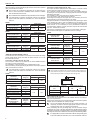 6
6
-
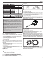 7
7
-
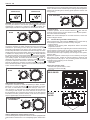 8
8
-
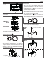 9
9
-
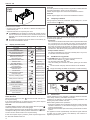 10
10
-
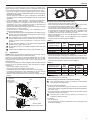 11
11
-
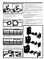 12
12
-
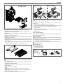 13
13
-
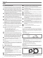 14
14
-
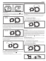 15
15
-
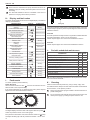 16
16
-
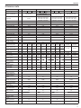 17
17
-
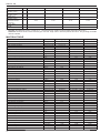 18
18
-
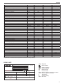 19
19
-
 20
20
-
 21
21
-
 22
22
-
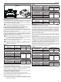 23
23
-
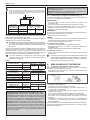 24
24
-
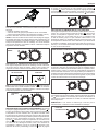 25
25
-
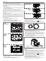 26
26
-
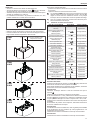 27
27
-
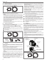 28
28
-
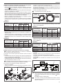 29
29
-
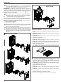 30
30
-
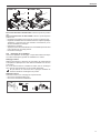 31
31
-
 32
32
-
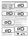 33
33
-
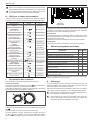 34
34
-
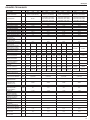 35
35
-
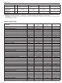 36
36
-
 37
37
-
 38
38
-
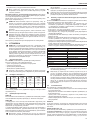 39
39
-
 40
40
-
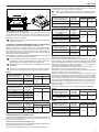 41
41
-
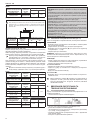 42
42
-
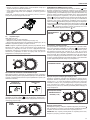 43
43
-
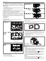 44
44
-
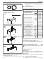 45
45
-
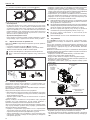 46
46
-
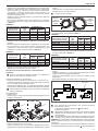 47
47
-
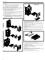 48
48
-
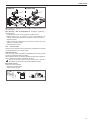 49
49
-
 50
50
-
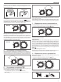 51
51
-
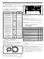 52
52
-
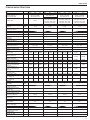 53
53
-
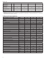 54
54
-
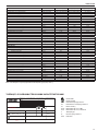 55
55
-
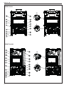 56
56
-
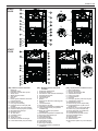 57
57
-
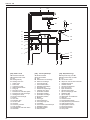 58
58
-
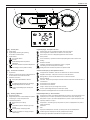 59
59
-
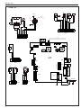 60
60
-
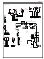 61
61
-
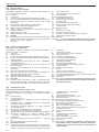 62
62
-
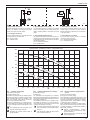 63
63
-
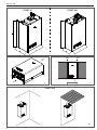 64
64
-
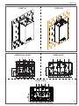 65
65
-
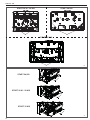 66
66
-
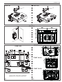 67
67
-
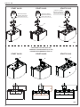 68
68
-
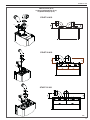 69
69
-
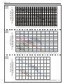 70
70
-
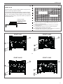 71
71
-
 72
72


Riello START 28 KI NG Manuel utilisateur
- Taper
- Manuel utilisateur
- Ce manuel convient également à
dans d''autres langues
- English: Riello START 28 KI NG User manual
