
Instructions
for the use and installation
of gas cookers
Notice d’emploi
pour l’installation et l’utilisation
des cuisinieres à gaz
F
GB


GB 3
MODELS SPECIFICATIONS
Fig. 1
INSTRUCTION FOR USE
COOK-TOP
This owner’s manual is valid for the Country mentioned
on the appliance.
Keep this manual close to hand and preserve it for any
further consultation.
The packing components (plastic bags, foamed polystyrene,
nails, etc...) are a source of potential risk; never leave them
within the reach of children.
If you use the grill keep the oven door half-open and the
grill deflector assembled as shown in the instructions booklet.
The glass cover (only on some models), before lighting the
over burners of the top and until their turning off, shall be
in open position; it is important to avoid any contact with
cookware during the cooking in order to save from a
dangerous overheating.
Important
After the cooker use it is recommended to:
1) always check that the knobs are in the “ ” position.
2) close the cock of the gas cylinder (if you use liquefied
gas) or the supply cock (in case of natural gas).
3) periodically check the wear of the hosepipe and replace
it if necessary. Do not repair it.
IMPORTANT:
The appliance must be installed only by qualified and
competent technicians in compliance with the national
provisions in force. Any modification that should be
necessary to the domestic system in order to install
the appliance shall be carried out by qualified technicians
only. The manufacturer declines all responsibility for
any damage caused by the non-observance of the rules
in force or due to an improper installation.
For any intervention please apply to an authorised aftersales
servicing centre and ask for original spare parts.
REMARK: during and after the use, the glass of the
oven door and accessible parts can be very hot; it is
therefore necessary to keep children away from the
appliance.
- Make sure that there is a regular air circulation around the
gas appliance. A poor ventilation reduces the oxygen.
In case of doubts consult the installer.
- The forming of fat or other food can start a fire. Carefully
mind the cooking with oils and fats.
- This appliance has been designed exclusively for the
cooking of food. Any other use (e.g. environment hating)
is considered improper and dangerous.
- Do not install the cooker near flammable material (e.g.
curtains, tea towels, etc...)
- Never clog the holes on the bottom of the oven. Do not
cover with aluminium sheets the oven walls, especially the
lower side.
- Always close the cock of gas supply before any cleaning
and maintenance operations.
- The oven parts in contact with food are made with materials
in compliance with the provisions of Directive EEC 89/109
dated 21/12/88.
- The cooker complies with the European Directives as to
gas EEC 90/395, EEC 93/88 and provisions EN 30-11 and
EN 2-1.
- Before operating on the unit remove the plastic films.
COOKER DIMENSIONS 90x60 90x60
AND CHARACTERISTICS with cylinder
compartment
Height of top a1 85 ± 2 cm 85 ± 2 cm
Depth c1 60 cm 60 cm
Width B 90 cm 90 cm
Height of topof open lid a2 141 ± 2 cm 141 ± 2 cm
Depth with oven door open c2 98 cm 104 cm
Working capacity 58 dm
3
135 dm
3
Class 2 subclass 1 2 subclass 1
Burners Burners adaptable for operation with LPG - natural gas
Operating voltage 230 Volt - 50 Hz
ATTENTION
Fig. 2
gas supply closed
maximum
gas position
minimum
gas position
★
BURNERS USE
MANUAL LIGHTING OF THE COOK-TOP BURNERS
Put a lighted match to the burner, hold down and press the
proper knob to the left up to the max .
Turn the knob to the minimum position in order to reduce
the flame (small flame).
On the control panel next to each knob is drawn a flame
schema where it is indicated the burner position to which
the knob refers to. (fig. 2).
B
a
2
a
1
100
C
2
C
1
B
a
2
a
1
100
C
2
C
1

REMARKS
The gas cooker during its
operating produces heat and
humidity in the room where it
is installed.
Therefore the local needs a
good airing; keep unclogged
the opening of the natural
ventilation and activate the
airing mechanical device
(extractor hood or electric fan).
In case of an intensive or long use of the appliance it is
necessary additional airing, e.g. open a window or more
effective ventilation increasing the power of the mechanical
aspiration (if any).
If the appliance is equipped with cover in tempered glass,
this can burst if overheated.
Turn off any burner before closing the cover.
The cooker with enamelled support grids are supplied with
a small reduction grid which shall be used for heating
cookware of small diameter, exclusively on the auxiliary
burner.
In case of convex pots (wook-type) it is necessary to use
on the Kwali triple-crown burner grid, the special reduction
grid, while if you use normal cookware with flat bottom it is
necessary to put on the grid a ring in order improve the
burner functioning.
USING ELECTRIC PLATES
The electric heating plates can be put on by turning the
proper knob on the control panel (fig. 4). A yellow light
indicates its functioning. The cooker is equipped with the
following plates:
Fig. 4
6
4
5
3
2
1
LIGHTING THE BURNERS OF THE COOK-TOP
EQUIPPED WITH SAFETY THERMOCOUPLE
(automatic stop of gas supply in case of accidental flame
putting out).
In case of lack of electricity light the burner with a match,
following the instructions given in the previous paragraph.
After lighting keep hold down the knob for about 10 seconds.
The gas supply can be cut off by turning the knob clockwise
on the position (gas supply closed).
Suggestions for saving energy
Avoid using pans that are too small for the burner, so that
the flames don’t reach high up the sides of the pan. When
the contents has boiled, reduce the flame setting to a simmer
by turning the knob anticlockwise. To facilitate saving gas,
the hob has burners with different diameters and power
ratings. Use the appropriate burner for each type of pan,
as detailed below:
The Oven and Grill Configuration
Rapid burner R Pan diameter from 24/25 cm
Semi-rapid burner B Pan diameter from 16/18 cm
Auxiliary burner A Pan diameter from 12/14 cm
Kwali triple flame burner BK Pan diameter from 24/25 cm
Fig. 3
RIGHT WRONG
Standard plate: Ø 110 P = 800 ÷ 700 W
Ø 145 P = 1000 W Rapid P = 1500W
Ø 180 P = 1500 W Rapid P = 2000W
Every plate is controlled by a 7 positions selector (6 working
position + 0). The highest position corresponds to the max
power, while the position 1 is the minimum.
The right quantity of heat for cooking can be obtained by
selecting intermediate positions.
PRACTICAL ADVICE
During the first plate insertion and in order to eliminate any
trace of residual humidity in the insulator, arrange for its
drying by switching on the plate for 30 minutes in position
1 without cookware.
It is possible to save energy consumption by using cookware
with flat and thick bottom (fig. 5). Never use cookware with
diameter lower than the plate.
Do not forget the plates on without cookware or with
empty vessels and make sure that the bottom of the
cookware is perfectly dry.
For a good preservation, after the use the plate shall be
lightly greased with a cloth soaked with oil so that the surface
appears clean and shining.
OVEN AND GRILL
USING THE GAS OVEN
Manual lighting of the oven
Open the oven door. Put a flame to the proper holes present
on the bottom of the oven (fig. 6), hold down and turn to the
left the proper knob on the control panel marked by the
symbol up to the maximum position (big flame).
Once it is on, keep pressed the knob for about 10 seconds
and make sure that the burner is lighted observing it by the
hole (fig. 6). The flame can be reduced turning the knob up
to the minimum position (small flame) and acting on the
temperature selected.
Before introducing food it is
recommended to heat the oven
for 15 minutes at the maximum
position. For the lighting of the
oven burner equipped with
thermostat, follow the above
mentioned instructions, keeping
in mind that the indicator of the
control knob shall be turned to
the max. position (fig. 7).
YES NO
Fig. 5
Fig. 6
4 GB

POSITION OVEN COOKING
FOOD
OF THE TEMPERATURE TIME
OVEN GRID °C
Meringue - Sweets 40 min.
HIGH 150 - 170°C
Legumes - Flat bread 45 min.
MEDIUM Soufflè - Puddings 35 min.
180 - 200°C
HIGH Pigeon - Pheasant 65 min.
MEDIUM Cakes - Short pastry 30 min.
210 - 230°C
HIGH Chicken - Veal 80 min.
Lamb - Pork 60 min.
MEDIUM 240 - 260°C
Dentex - Lasagne 90 min.
MEDIUM Pizza - Gratins 30 min.
270 - 280°C
LOW Bread - Fish 50 min.
Fig. 9/1
Fig. 8 Fig. 9
The oven burners are provided
with safety thermocouple
(automatic stop of gas supply
in case of accidental flame
putting out).
Therefore keep pressed the
knob for about 10 seconds.
If the burner is off, release
the knob and wait for a
minute before trying again
with the lighting.
In case of accidental burner put out, turn the knob in
closed
position and wait for one minute before relighting it.
REMARK
During and after the use, the glass of the oven door
and accessible parts can be very hot, it is therefore
necessary to keep children away from the appliance.
The oven parts in contact with food are made with
materials in compliance with the provisions of Directive
EEC 89/109 dated 21/12/88.
INDICATIVE TABLE FOR USING THE OVEN
The data reported are purely as and indication: experience
and personal taste will suggest you any variations for the
best use of the appliance.
285
205
235
min
150
175
max
Fig. 7
USING THE GAS GRILL
Manual lighting of the grill burner
Open the oven door completely. Put a lighted match to the
grill burner which is on the upper side of the oven (fig. 8).
Press and turn to the right the oven knob up to the grill
position (fig. 7). Check that the flames of the burner are
regularly lighted on both sides.
Using the turnspit
(available on some models)
The turnspit is operated by turning the oven knob to encounter
the symbol together with the grill.
First of all, place the food on the spit, using the two special
forks to hold it in place. Take care to distribute the weight
evenly, to prevent unnecessary strain on the motor (fig. 9/1).
Then place the end of the spit in the motor hole, and the
opposite end on its special support. Unscrew and remove
the plastic handle and turn on the grill. The oven burners
are provided with safety thermocouple (automatic stop of
gas supply in case of accidental flame putting out). Therefore
keep pressed the knob for about 10 seconds.
If the burner is off, release the knob and wait for a minute
before trying again with the lighting.
In case of accidental burner put out, turn the knob in closed
position and wait for one minute before relighting it.
ATTENTION
During the use of the grill the door of the oven shall be
opened. It is besides necessary to insert the grill deflector
- D- as shown in fig. 9. Put the tongues in the slots F or P
placed on the upper front side of the oven. Then fix the
deflector pressing it downwards.
This prevents an overheating of the control panel available.
IN SOME MODELS IT'S POSSIBLE TO GRILL WITH THE
OVEN DOOR CLOSED ,IN THIS CASE READ THE
ALLEGATE INSTRUCTION "COOL DOOR SYSTEM"
ATTENTION
During the grill functioning, the accessible parts can be
hot. Keep the children at a safe distance.
COOKING WITH THE GRILL
Before introducing the dishes, let the radiant plate grow
redhot, and then arrange the dishes on the grid and position
the dripping-pan on the immediately lower guides for the
dripping collection. The oven parts in contact with food
are made with materials in compliance with the
provisions of Directive EEC 89/109 dated 21/12/88.
COOL DOOR SYSTEM
During use of the grill burner on its own or simultaneously
with theoven burner, the oven door must be SHUT.
This prevents overtheating of the control panel.
CAUTION: Check that the gas pressure at the cooker
inlet isas required:
LPG: 280-300 mm H
2O
Natural Gas: 180-200 mm H
2O
Pressure different from those indicated may cause the
applianceto overheat dangerously.
GB 5

Thermostat function orange pilot light lamp it indicates
the phase of oven heating.
HOW TO COOK
The red pilot light signals that a heating element is operated.
At the first use of the oven, it’s normal to smeel the protective
oils used in manufacture burning off.
Leave oven on maximum setting for approximately one hour
before use.
N.B. Before carryng out cleaning, disconnect the
appliance from electrical supply.
At the end of the initial heating, let the oven cool down and
clean he inside with detergent and warm water. Before
using, wash all grid accessories, baking-pan and trays.
General information and use precautions
- Always hold the handle in the middle, to open the oven
door.
- When you open the oven door, beware hot vapour.
- Use protective gloves to insert or to extract containers
from the oven.
- Use containers resistant to the temperatures indicated on
the thermostat knob.
- After use of the oven, be sure that all controls are in the
off position.
Oven light
The symbols present on the oven control knob are different
according to the models. The first function common to all
is the oven light bulb switching on, identified by the symbol
. Once selected, the bulb light is on during other oven
functions.
Turnspit
The turnspit, marked with the symbol is an optional
available only in some models. Its symbol is next to the
oven function symbols, for example when
selecting the function “simple grill” the “turnspit” will
automatically operate too.
Cooking functions
Simple grill
This function operates the top central element which radiates
heat directly over the foods. Set the max temperature by
means of the thermostat. The oven door must be kept
closed.
Double grill
This function switches on both top elements to radiate heat
directly over the foods it is possible to use this function
turning the thermostat knob to the max temperature 200°c
The oven door must be kept closed.
Static oven
Traditional cooking with natural convention. This function
operates the top and bottom elements and the foods are
evenly cooked. Turn the thermostat knob to the chosen
temperature.
This function is suitable for cooking most food (meat, fish,
bread, pizza and so on).
Fan oven
This function operates the back circular element and the
heat is very quickly spread in the oven by means of an
electric/motor fan. The foods are rapidly and evenly cooked
even if placed on more than one shelf.
It is possible to use this cooking mode turning the thermostat
knob to the chosen temperature.
Fan double Grill
This function operates both top elements to radiate the heat
directly over the food; the heat is spread very quickly in the
oven by means of an electric fan.
It is possible to use this function, turning the thermostat
knob to the temperature 200 °C.
This cooking mode is particularly suitable to get an evenly
and crisp browning.
Conventional electric fan cooking
This function operates top and bottom elements and the
heat is spread over the foods by means of an electric fan.
Turn the thermostat knob to the chosen temperature. This
cooking mode is suitable for cooking foods on a single shelf.
Delicate cooking
This function operates the bottom element. Turn the
thermostat knob to the chosen temperature.
This mode is suitable for re-cooking, if it is necessary to
increase the cooking degree in the lower side of foods.
6 GB
WARNING LIGHTS
USING THE ELECTRIC OVEN

GB 7
Caution:
Model 90x60 with cylinder compartment
Gas oven and electric grill
When using the grill, open the oven door and fit the guard
as shown in the diagram.
The guard becomes very hot during use; keep children well
away. After cooking, allow the guard to cool.
Warning:
Model 90x60
Gas oven and electric Grill
when using the electric grill turn the oven dial to 0, keep the
oven door closed, turn the energy setting (fig A) to the
highest position 5 for 90x60 models (fig B) .
USING THE ELECTRIC GRILL
Fig. A
Fig. B

ATTENTION
- During the functioning the oven door is hot. It is
recommended to keep children at safe distance.
The use of detergents, abrasive powders or paste, can
damage the surfaces.
It is recommended to clean immediately any lemon spots,
vinegar and acid substances, in order to preserve the enamel
brightness.
The grids and burners can be taken away and easily washed
in warm water and soda.
OVEN
It is advisable to clean the oven periodically. While it is still
warm clean with a cloth soaked with warm water and
detergent, followed by a careful rinsing and drying.
The bottom of the oven can be easily extracted and washed
in the washbasin together with dripping-pan and gridiron
shelf.
IMPORTANT:
Check the wear of the gas hosepipe connecting the
cooker to the cylinder and replace it in case of anomalies.
It is recommended to change it yearly; in any case within
the date impressed on the hose.
The replacement of spare parts and maintenance
operations shall be carried out by qualified personnel
only.
8 GB
GENERAL GUIDELINES
All servicing operations described in this section must be
carried out by qualified personnel only.
Before starting any servicing operations on a cooker, it must
be unplugged or switched off at the mains supply. If work is
to be carried out on the electrical or gas components
underneath the hob (e.g. switches, thermostat taps, etc.)
follow the order shown in Fig. 11 below.
1) remove the pan supports.
2) remove the burners and unscrew the screws as shown
in Fig. 11.
3) unscrew the 4 screws on the back of the cooker (Fig. 12).
Having completed the above, remove the hob.
Fig. 11
Fig. 12
Fig. 13
To remove the control panel, follow the instructions in
Fig. 13, removing knobs “A” and unscrewing the screws
“B”. To replace the hob and control panel, repeat the
operation in reverse.
Fig. 14
Fig. 15
REPLACEMENT OF THE TAPS
When replacing a tap, follow the instructions below:
- Remove the knobs by pulling.
- Remove the hob and the control panel following the
sequence of instructions in Fig. 11-12-13.
- Unscrew the lock nuts “C” from the junction ramp between
the burner (Fig. 14).
- Lift the mounting support and unscrew screws “E” (Fig.15).
- Partially lift the ramp.
- Unscrew screws “F” to remove the tap.
- Replace the seal when replacing a tap to ensure a perfect
seal between the body and the ramp.
REPLACEMENT OF THE BURNERS AND SWITCHES
- To replace these accessories, remove the hob following
the sequence of instructions in Fig. 11-12-13.
- To take the burners apart follow the sequence of instructions
in Fig. 15b.
Unscrew the lock nuts “C” and “D” and screws “E” (Fig.15b)
Fig. 15b

USE OF ACCESSORIES
Timer
Your range can be fitted with this accessory that you can
wind by rotating the corresponding knob clockwise by one
complete turn and set the pointer to the desired cooking
time (expressed in minutes) by rotating the knob
counterclockwise.
The set time running out will be signaled by a bell.
Electric timer
Your range can be fitted with this accessory acting both as
a clock and as a timer as well. To set hour push and rotate
the small knob counterclockwise. To set minutes rotate the
small knob counter clockwise without pushing it.
Timer with cooking end function
Your range can be fitted with this double functional accessory:
it can show the cooking time that has already passed and
automatically turn off the oven. You can set the desired
cooking time by rotating the timer knob clockwise by one
complete turn and set the pointer to the desired cooking
time (expressed in minute); when this time has passed the
acoustic warning signal switches on and contemporaneously
the automatic cooking end device starts.
As far as the oven connection modes are concerned please
refer to the handbook specific paragraphs.
If you desire to use the oven without the timer function you
should turn the knob to the symbol (manuel).
N.B. When the knob pointer is set to “0” position, oven
cannot work.
Electric clock supplied with cooking end device
Range can be fitted with this double functional accessory:
it consists of a clock able to turn off oven automatically when
the set cooking time has run out.
To set hour push and rotate the small knob counterclockwise.
To set minutes rotate the small knob counterclockwise
without pushing it. When the set time has run out the acoustic
warning signal starts to inform that oven is off.
Turn the knob to the symbol to stop it.
If you desire to use oven without setting a cooking time you
should rotate the knob pointer counterclockwise to the
symbol (manuel).
N.B. When the knob pointer is set to “0” position and to
symbol, oven cannot work.
Electronic programmer
Your range can be fitted with this accessory whose main
functions are:
- Clock (to be set with push buttons 2 and 3).
- Timer (to be set with push button 1).
- Cooking time (to be set with push button 2).
- Cooking end time (to be set with push button 3).
- Manual working (to be set with push button 4).
- Regulation of times “backward” (to be set with push button
5).
- Regulation of times “forward” (to be set with push button
6).
The digital display “D” (see pict. 4 at the end of this handbook)
shows the hour, the cooking time and the cooking end time.
Time setting
After the electric connection or a lack of current, on the
display the “AUTO” e “0.00” signals will flash at the same
time. Push and release contemporaneously push buttons
2 and 3 and start setting the current hour by pushing either
button 4 or 5 within 4 seconds. Once the setting is over no
symbol will be on.
Timer
Push button 1 and select your cooking time by means of
either button 4 or 5.
The symbol will lit up.
When the set time has run out, the acoustic warning signal
starts and the symbol will flash. After the bell disconnection
that symbol will disappear.
Half-automatic working mode (cooking time)
By pushing button 2 and setting the cooking time by means
of button 5, both the “AUTO” and the symbol will lit up.
When the set time has run out, the symbol will switch off
while the “AUTO” symbol flashes and the acoustic warning
signal starts.
Half-automatic working mode (end of cooking time)
By pushing button 3 and setting the end of cooking time by
means of button 5, both the “AUTO” and the symbols will
lit up. When the set time has run out, the symbol will switch
off while the “AUTO” symbol flashes and the acoustic warning
signal starts.
Automatic working mode (postponed cooking start time)
First you should set your cooking time (both the “AUTO”
and the symbols will lit up) and then the cooking end time,
the symbol will switch off as previously stated.
The symbol will lit up again when the oven starts baking.
When cooking time has run out, the symbol will switch
off while the ”AUTO” symbols flashes and the acoustic
warning signal starts.
Manual working
Manual working is possible only after having cleared the
automatic program by pushing button 3. The “AUTO” symbol
disappears and no other symbols lit up.
Acoustic warning signal
The acoustic warning signal starts at the end of a program
and lasts about two minutes. To interrupt it you should push
one of the function buttons.
Program start and check
Program starts after about 4 seconds from the setting. It is
possible to check the set program at any time by pushing
the corresponding button.
Correction and cancellation of program
It is possible to correct the set program at any time by first
pushing the relative programming button and then buttons
4 or 5. It is possible to cancel a program by changing the
set time to “0.00”. By cancelling the working time you will
automatically cancel the working end time and vice versa.
Oven automatically switches off while the “AUTO” symbol
flashes. Push button 3 to set the programmer to manual
working mode. Time cannot be corrected when the automatic
working program is on.
FEED CABLES TYPES TYPE OF INPUT
AND SECTION CABLE 220 V~
TOTAL GAS H05 RR-F 3x0,75 mm
2
MIXED UP TO 660 W H05 RR-F 3x1 mm
2
MIXED UP TO 1320 W H05 RR-F 3x1,5 mm
2
MIXED UP TO 2200 W H05 RR-F 3x2,5 mm
2
MIXED UP TO 3520 W H05 RR-F 3x4 mm
2
GB 9

TECHNICAL INFORMATION
FOR THE INSTALLATION
The installation and regulations shall be carried out by
qualified technicians only. After removing external packaging
and inside packing of movable parts, make sure of the
integrity of the appliance. In case of doubts do not use the
appliance and turn to qualified technicians.
Never leave packing components (carton, bags, foamed
polystyrene, nails.....) within the reach of children as they
represent potential dangers.
ASSEMBLY OF ADJUSTABLE LEVELLING FEET
Remove the packaging of the cooker. Assemble the feet
which are in the accessories kit, fitting them in the proper
fixed seats placed on the four corners of the cooker.
(fig. 16 – fig. 16/a). Align or level the cooker with other
furniture by adjusting the foot.
Fig. 16 Fig. 16/A
REMARKS FOR THE INSTALLATION
The installation shall be carried out in compliance with the
national rules in force. Install the appliance in a well-aired
room. Check that the flux of the gas meter and the diameter
of the ducts have enough capacity for all the appliances and
that the connectors are water-tightness. The gas cookers
belong to Class I and therefore they shall not be put closer
to furniture. The walls next to the cooker shall be resistant
to a temperature of 75° C. (fig. 17) or covered with insulating
material. The cooker shall be installed at a distance of 20
mm from the walls and the cook-top 650 mm from the
suspended wall unit (fig. 17/a). The gas cookers belong to
class II can be lean agains the walls ( fig.17/b )
150 mm Min
650 mm Min
0 mm Min
CLASS II under Class I
Type Y
Dimensions
shown apply
to BOTH
sides of the
appliance
Applies
to base
&wall units
(if fitted)
Fig. 17/b
ROOMS VENTILATION
Attention: this appliance can be installed and used only
in constantly ventilated rooms according to the national
rules in force. The right functioning of the cooker is ensured
by the installation in a constantly ventilated room. The flow
of air for a regular gas combustion and ventilation shall not
be less than 20 m
3
. The natural influx of air shall be directly
from the outside through openings on the wall of the room
with a cross section of at least 100 cm
2
. These openings
shall be made in a way that can’t be clogged. It is allowed
the indirect airing through the extraction of air from adjacent
rooms (fig. 18) in compliance with the national regulations
in force.
ATTENTION:
The section of the ventilation opening of a cooker with
burners not fitted with safety thermocouple should be
at least 200 cm
2
.
POSITIONING
The gas cookers shall discharge smokes and gases from
combustion by means of hoods connected to chimneypots,
flues or directly outside. In absence of a hood it is permitted
the use of a ventilator installed on a window or on a wall to
the outside, which shall be operate simultaneously with the
appliance on condition that the national rules in force are
complied with.
Wider opening
between door
and floor
Fig. 18
CONNECTION TO THE GAS SYSTEM
Important: the installation shall be made according to the
national rules in force. Install the appliance in a well-ventilated
room; check that the capacity of the gas meter and the
hosepipes diameter are enough to supply power to all
appliances connected. Do not forget to install, upwards
the appliance, a gas cock of at least 1/2”, visible and
reachable.
Before connecting the appliance check the data reported
on the plate placed inside the chafing dish door or on the
back of the cooker reporting the type of gas, pressure and
capacity of the cooker.
Connection to canalized gas system: the cooker shall be
connected as indicated (fig. 19), by using:
- non-flexible steel metal pipe, copper pipe, flexible stainless
steel hosepipe, rubber flexible hosepipe, the hosepipes.
Shall be in compliance with the national rules in force. In
case of natural gas the supply pipe shall be put on the big
tubeholder (B) after screwing and taking away the reduction
unit (A) (liquefied gas tubeholder) (fig. 19.)
CONNECTION TO LIQUEFIED GAS-CYLINDER SPACE
The cookers with support for cylinders are regulated for
being used with LPG.
The support cylinder space is 620 mm high and 325 mm
wide and can contain standard cylinders of 10 kg.
10 GB
150 Min
650 Min
20 Min
25 cm60 cm
Fig. 17 Fig. 17/A

Fig. 20 Fig. 21
Provide the cylinder with a gas pressure reducer.
By a hosepipe of 8 mm. connect it to the reducer A, screwed
on the cylinder support B (fig. 19) of the cooker ready for
the connection, arranging then the cylinder in the special
space (fig. 20).
IMPORTANT: follow these guidelines:
1) The flexible hosepipe shall be from 400 mm up to 800
mm. long and conform to the standards.
2) The cylinder support of the reducer shall be faced to the
right side of the cylinder support space.
3) The hosepipe connection to the reducer/cooker cylinder
supports shall be
carried out as indicated
in fig. 20, i.e.: entering
the support place
upright and coming out
from the cooker by the
special back hole. For
the fastening operation
use clamps conform to
the standards.
4) Arrange the cylinder in the special space not in contact
with the oven wall.
5) During the cylinder change, do not remove the tube from
its crossing.
6) Before inserting the cylinder take away the plastic base
as shown in fig. 21.
Fig. 19
Fig. 22
IMPORTANT:
The hosepipe shall not present narrowing and be far
from heat sources, especially the back of the oven.
After the connection, check that the pipes are properly
sealed, using a soapy water solution on the joints.
The flexible hosepipe shall never cross from one side
of the appliance to the other and be visible. In the need
of a connection on the opposite side of the one provided,
ask the manufacturer (see the address in the overleaf)
for additional metal hosepipe D (fig. 20-22).
The additional pipe can be assembled as follows:
a) remove the
tubeholder of fig. 19
and turn the “cross”
coupling C fig. 22.
b) Screw the metal
pipe to the coupling
putting in the seal G
and fix it on the back
of the cooker by the
screw E.
c) Assemble the tubeholder on the other end of the pipe
putting in the seal G.
Carry out the connection by a proper pipe in conformity with
the regulations making sure that it is perfectly put on the
tubeholder and tightened by a proper fixing clamp.
Remark: the gas supply connector of the appliance is a
threaded male 1/2” for round gas pipe and conforms to
UNI-ISO 228-1.
The flexible hosepipe shall be replaced within the date
indicated on the pipe.
Attention: the installer must ascertain that the national
provisions in force have been complied with.
The manufacturer declines all responsibility for the
nonobservance of the above mentioned regulations.
GB 11
CHANGING THE INJECTORS
FOR THE DIFFERENT TYPES OF GAS
Hob Burners:
- remove the pan stands, the flame dividers and the burner
heads from their mountings;
- select from the pack of injectors, checking the corresponding
indication on the injector, the appropriate one for each
burner and for the desired type of gas;
- using a 7 mm spanner unscrew the injectors fitted (Fig.
23). Replace them with the appropriate injectors and tighten
them without excessive force;
- replace the heads and the caps of the burners on the
burner cap supports;
- adjust the low settings as indicated in the chapter “Adjusting
the low settings” below.
Fig. 23b
Fig. 23
ADAPTATION FOR DIFFERENT TYPES OF GAS
To adapt the cooker for a different type of gas than that for
which it was designed (see the labels on the inside of the
Plate Warming Door), carry out the following operations:
a) disconnect the appliance from the mains to avoid any
accidental contact.
b) replace the burner injectors on the hob:
c) adjusting the minimum settings of the hob burners
No adjustment of the burner primary air is required.
Once the gas regulation is completed, replace the data
plate inside the plate warming door with the correct one
supplied with the injector set.

BEFORE CALLING
THE AFTER-SALES
SERVICING CENTRE
If the appliance does not function correctly, before turning
to after-sales servicing centre check the following:
The gas flux is not regular.
Make sure that:
- the holes of the burners are not clogged
- in the cylinder there is still enough gas
- the pressure regulator is functioning
- the valve of the cylinder is completely open
There is smell of gas in the room
Make sure that:
- a cock is not open
- the gas supply pipe is well positioned or in good condition,
remember to replace it once per year.
Do not search a lack of gas with a match; check the
seal by soapy water.
The oven or the grill do not heat
Make sure that the oven knob is ON
Cooking times too long
Check that the temperature set is the most suitable for the
food to be cooked.
The oven sends out smokes
It is recommended to clean it after any use. During meat
cooking it is possible the forming of fat splashes that, if not
cleaned, could case smoke and smell to the following cooking
(see the paragraph regarding the cleaning). If after the above
mentioned check the appliance does not function turn to
the nearest servicing centre, supplying any data relative to
the appliance model and serial number.
COOKERS:
90x60
90x60
grill with
doorclosed
90x60
with cylinder
compartment
OVEN AND GRILL BURNER
Oven
with thermostat
Grill
Oven
with thermostat
Grill
Oven
with thermostat
Grill
5000 1800 107 305 160 400
3200 - 82 230 120 323
5000 1800 107 305 160 400
3000 - 80 218 115 285
3100 950 85 225 115y 294
2000 - 70 145 102z 190
GAS CONNECTION
L.P.G. 30 mbar
NATURAL
THERMAL CAPACITIES DETERMINED WITH THE HIGH HEATING VALUE OF THE GAS AT 15°C-1013mbar
12 GB
Fig. 24
GRILL
OVEN
b - Oven burners
Remove the oven accessories,
the lower plate and unscrew the
back screw D, fixing the burner
to the bottom of the oven, in
order to take it away and enter
the injector (fig. 24)
By means of the socket wrench
of 7 mm. unscrew the injector.
Once the proper injector has
been assembled, remount the
burner of the oven.
c - Grill burner
It is possible to enter the injector
taking away the burner fixed on
the top of the oven by the front
screw D (fig. 24).
Change the injector in the same way as per the oven and
reassemble the grill.
It is recommended to put the replaced injector in the proper
accessory kit and preserve them.
WARNING
Check that the gas pressure at the entry of the appliance
is the correct one.
L.P.G. 30 mbar Natural gas 20 mbar
ADJUSTING THE LOW SETTINGS (REDUCED FLOW)
Adjusting the low settings of the hob burners (Fig. 23b)
- light one burner at a time, in the fully on position, remove
the knob using a screwdriver, unscrew by approximately
three turns minimum screw H located on the right hand
side of the stem, turn the tap to the left to the reduced gas
flow position and turn screw H until a small regular flame
is obtained.
With butane or propane gas the screw will be screwed fully
down. These screws are pierced and mounted on the tap
according to the type of burner.
BUNERS TYPE
Max power 1,0 kW - 73 g/h (G30) - 71 g/h (G31)
Min power 0,45 kW
Gas G20 G30/31
Pressure (mbar) 20 28-30/37
Injector (1/100 mm) 77 50
by-pass (1/100 mm) Regulated 32
Max power 1,75 kW - 127 g/h (G30) - 125 g/h (G31)
Min power 0,5 kW
Gas G20 G30/31
Pressure (mbar) 20 28-30/37
Injector (1/100 mm) 101 66
by-pass (1/100 mm) Regulated 34
Max power 3,0 kW - 218 g/h (G30) - 214 g/h (G31)
Min power 0,8 kW
Gas G20 G30/31
Pressure (mbar) 20 28-30/37
Injector (1/100 mm) 129 87
by-pass (1/100 mm) Regulated 42
Max power 3,8 kW - 276 g/h (G30) - 271 g/h (G31)
Min power 1,35 kW
Gas G20 G30/31
Pressure (mbar) 20 28-30/37
Injector (1/100 mm) 145 98
by-pass (1/100 mm) Regulated 57
Max power 3,5 kW - 255 g/h (G30) - 250 g/h (G31)
Min power 1,35 kW
Gas G20 G30/31
Pressure (mbar) 20 28-30/37
Injector (1/100 mm) 144 94
by-pass (1/100 mm) Regulated 57
UR TC
A
SR
R

FR 13
RENSEIGNEMENTS
TECHNIQUES
CARACTERISTIQUES DIMENSIONNELLES
DES CUISINIERES
INSTRUCTIONS POUR L’UTILISATEUR
LA TABLE DE CUISSON GAZ
ATTENTION
Ce mode d’emploi est valide quand le pays de destination
est le même que celui indiqué ci-dessous et sur
l’appareil.
• L’installation, la mise en service et la vérification de l’état
de bon fonctionnement doivent être effectuées
exclusivement par une personne qualifiée, suivant les
normes en vigueur et conformément aux instructions du
constructeur. Les instructions spécifiques sont données
au chapitre des informations destinées à l’installateur.
Important
Après l’usage de la cuisinière:
1) Fermer le robinet de débit placé à mont de l’appareil.
2) Contrôler périodiquement que le tuyau de caoutchouc
soit en bon état et éventuellement le remplacer.
Il ne faut absolument jamais le réparer.
Respecter la date limite d’utilisation.
N.B.:
Le modèle des cuisinières, les valeurs techniques
(puissance, tension d’alimentation ect.) se trouvent sur
une étiquette au dos de la cuisinière, ou dans l’étuve.
L’étiquette avec les indications pour le réglage est placée
sur le couvercle de la cuisinière.
REMARQUE
Attention: “la porte est chaude pendant le
fonctionnement.
Eloigner les jeunes enfants”.
ATTENTION. “les parties accessibles peuvent être
chaudes quand le grilloir est utilisé. Eloigner les jeunes
enfants”.
CONDITIONS REGLEMENTAIRES D’INSTALLATION ET
D’ENTRETIEN
L’installation et l’entretien de l’appareil doivent être effectués
par un professionnel qualifié conformément aux
textes réglementaires et règles de l’art en vigueur,
notamment:
- Arrêté du 2 août 1977
Règles Techniques et de Sécurité applicables aux installations
de gaz combustible et d’hydrocarbures liquéfiés situées à
l’intérieur des bâtiments d’habitation et de leur dépendances.
- Norme DTU P 45-204 - Installations de gaz (anciennement
DTU n° 61-1 - Installations de gaz - Avril 1982+ additif n°
1 Juillet 1984).
- Règlement Sanitaire Départemental
Pour les appareils raccordés au réseau électrique:
- Norme NF C 15-100 - Installations électriques à basse
tension - Règles.
- Cet appareil doit être installé conformément aux
réglementations
en vigueur, et utilisé seulement dans un endroit
bien aéré. Consulter les notices avant d’installer et
utiliser cet appareil. Le volume de renouvellement d’air
necessaire est de 2 m
3
/h par kW.
- Tous nos appareils sont projetés et construits selon
les normes Européennes EN 30-1-1 et EN 30-2-1.
- Les appareils sont conformes aux prescriptions de la
directive gaz communautaire CEE 90/396 et 93/68 CEE.
-Avant d'operer sur la cuisiniere il faut enlever les
protections en plastique.
Fig. 2
fermé
ouvert
au MAX
MIN ralenti
Fig. 1
B
a
2
a
1
100
C
2
C
1
B
a
2
a
1
100
C
2
C
1
CUISINIERE DIMENSIONS 90x60 90x60
SELON LES avec porte
bouteille
Hauter à la table de cuisson a1 85 ± 2 cm 85 ± 2 cm
Profondeur (tout compris) c1 60 cm 60 cm
Largeur (tout compris) B 90 cm 90 cm
avec porte bouteille
Hauter à couvercle ouvert a2 141 ± 2 cm 141 ± 2 cm
Profondeur avec porte c2 98 cm 104 cm
du four ouverte
Capacité utile du four 58 dm
3
135 dm
3
Classe 2 subclass 1 2 subclass 1
Brûleurs
Brûleurs adaptables pour gaz Butane - Propane et gaz naturel
Voltage 230 Volt - 50 Hz
BRULEURS GAZ
Sécurité - Chaque brûleur est contrôlé par un robinet à
verrouillage de sécurité dont l’ouverture s’effectue en poussant
puis en tournant la manette vers la gauche.
Au-dessous de chaque manette figure le point de repére du
brûleur correspondant fig. 2.
Signification des symboles:
: ouvert au maximum : ralenti l: fermé

HAUTEUR DE LA FLAMME
Réglez la flamme en variant la position de la manette entre
les positions “ouvert” et “ralenti” .
ALLUMAGE DES BRÛLEURS
• Pour allumer:
Présentez une flamme au brûleur puis poussez et tournez
la manette du brûleur choisi, de la droite vers la gauche
jusqu’au repére .
• Pour éteindre, tournez la manette de la gauche vers la
droite jusqu’à la butée, sur la position “l” (arrêt). Le verrouillage
de sécurité est en place.
- ALLUMAGE DES BRÛLEURS DE LA TABLE DOTÉS
DE THERMOCOUPLE DE SÉCURITÉ (Arrêt automatique
du gaz en cas d’extinction accidentelle de la flamme).
Répéter les opérations indiquées au paragraphe précédent
et utiliser une allumette en cas de panne d’électricité. Après
avoir allumé, laisser la manette enfoncée pendant 10
secondes environ.
Brûleur rapide R1 diamètre à partir de 24/26 cm
Brûleur semi-rapide B diamètre à partir de 16/18 cm
Brûleur auxiliaire A diamètre à partir de 12/14 cm
Brûleur à triple couronne diamètre à partir de 24/26 cm
Kwali BK
BON MAUVAIS
Fig. 3
Plaques en fonte
Les cuisinières peuvent être équipées de deux types de
plaques électriques:
- normales
- rapides (rond rouge au milieu)
Les deux types de plaques sont contrôlés par des
commutateurs.
La plaque rapide offre l’avantage d’une cuisson plus rapide.
En tournant le bouton dans le sens des aiguilles d’une
montre nous trouverons les symboles inscrits ci-dessous:
0 = Plaque ou élément chauffant NON
BRANCHE
de 1 à 6 = Positions de la puissance MINIMALE
à la puissance MAXIMALE
Lors du premier branchement de l’appareil ou de
nonutilisation prolongée, il faut convient de faire fonctionner
la plaque pendant 30 minutes sur la position numéro 1 du
commutateur afin d’éliminer toute humidité accumulée.
Fig. 5
285
205
235
min
150
175
max
Fig. 4
LE FOUR GAZ
ALLUMAGE DU FOUR
Très important
- Lorsque le four ne fonctionne
pas veillez à laisser la
manette en position “fermé”
(repère l) (fig. 4).
- Respectez rigoureusement
l’ordre ci-dessous pour
procéder à l’allumage.
FOUR AVEC ROBINET THERMOSTAT
- Ouvrez la porte du four.
- Présentez une flamme devant
l’orifice d’allumage (fig. 5).
- Placez la manette du robinet
thermostat sur la position
max.
- Contrôlez l’allumage du
brûleur.
- Refermez la porte du four.
- Tournez la manette sur la
position choisie.
CONSEILS
Réglez la couronne de la
flamme pour qu’elle ne
déborde pas du pourtour du
récipient (Fig. 3).
Le plan de travail est en effet
équipé de brûleurs de
différent diamètre (et
puissance).
L’emploi des brûleurs doit
être réglé selon le type de
casserole c’est à dire:
NOTES
- L’utilisation d’un appareil de cuisson au gaz produit chaleur
et humidité dans le local où il est installé. Veillez à assurer
une bonne aération du local. Laisser ouverts les orifices
d’aération naturelle ou installer un dispositif mécanique
d’aération (hotte d’aspiration, ou électroventilateur).
Une utilisation intensive et prolongée de l’appareil demande
une aération supplémentaire par exemple l’ouverture d’une
fenêtre ou une aération plus efficace par exemple en
augmentant la puissance de la ventilation mécanique si elle
existe.
- Sur les appareils équipés de couvercle en verre il pourrait
y avoir des risques d’éclatement lorsqu’ils sont chauffés.
Eteindre tous les brûleurs avant de fermer le couvercle.
Les cuisinières avec grilles émaillées sont fournies avec
une grille de réduction qui doit être utilisée pour réchauffer
des récipients de diamètre inférieur à 10 cm et exclusivement
sur le brûleur auxiliaire. En utilisant des casseroles
convexes (type wook) il faut placer sur la grille du brûleur
à triples couronnes (kwali) la réduction spéciale, tandis que
si l’on utilise sur le même brûleur des casseroles
traditionnelles (fond plat) il faut interposer sur la grille un
anneau entretoise. Cet anneau augmente la performance
du brûleur.
FOUR ET GRILLOIR
Mise en service - conseils
Avant d’utiliser votre four pour la première cuisson, le laisser
chauffer à vide, pendant une demi-heure environ (manette
sur la position max). La laine minérale qui entoure le four
peut dégagerau début une odeur peu agréable due à sa
composition.
Logement chauffe-plats (si prevu)
Le logement chauffe-plats est destiné à recevoir la
casserolerie du four, moules à gâteaux, à tartes, etc.
Vous pouvez aussi l’utiliser comme chauffe-assiettes (four
allumé). Nous vous recommandons de ne pas y ranger de
casserolerie comportant des parties bois ou plastique ou
des matières combustibles (brosses, chiffons, etc.).
Pour ouvrir la porte du chauffe-plats il faut soulever
légèrement la partie inférieure de la porte ou la pousser,
selon les modeles.
Conseils
Manoeuvrez la porte du four doucement et ne la laissez
jamais entrouverte lorsque le four est chaud.
Vous risqueriez d’abîmer les manettes de commande.
Si, pendant la semaine, vous n’avez effectué que des
cuissons au four sans utiliser le grilloir, allumez cellui-ci en
fin de semaine pendant trois minutes.
14 FR

FR 15
UTILISATION DU FOUR A GAZ
Si le brûleur ne s’est pas allumé, lâcher la manette et
attendre au moins 1 minute avant de rallumer. Dans le cas
d’extinction accidentelle du brûleur tourner la manette sur
la position fermé et attendre au moins 1 minute avant de
rallumer. En cas de coupure de courant utiliser une allumette
pour allumer les brûleurs.
ALLUMAGE DU FOUR AVEC SÉCURITÉ
Pour les brûleurs de four avec thermocouple de sécurité
(arrêt automatique du gaz en cas d’extinction accidentelle
de la flamme), il faut maintenir appuyée la manette pendant
10 secondes environ, après avoir allumé le four.
LES ACCESSOIRES DU FOUR ET DU GRILLOIR
La lèchefrite
doit être utilisée uniquement pour recueillir le jus des grillades
et des cuissons au tournebroche.
La tôle à pâtisserie (si prevu)
s’utilise pour la cuisson des petits gâteaux, elle se pose sur
la grille support.
La grille support
est utilisée pour recevoir les plats à rôtir, à gratiner, les
moules à pâtisserie et les pièces à griller. Les gradins vous
permettent de varier la position dans le four.
REMARQUES
- Pendant et après l’utilisation la porte du four et les
parties accessibles peuvent être très chaudes.
Eloigner les jeunes enfants.
- Les accessoires du four qui peuvent entrer en contact
avec les aliments, sont construits avec des matériaux
conformes à la directive CEE 89/109 du 21/12/88.
Pendant et après l’utilisation, le verre de la porte four
et les parties accessibles peuvent être très chaude.
Eloigner les enfants de l’appareil.
TABLEAU D’UTILISATION DU FOUR
Ce tableau est indicatif, les essais ci-dessous reportés ont
été effectués en utilisant la lèchefrite ou la grille normalement
fournies avec l’appareil. Placer la grille ou la léchefrite sur
le 3ème gradin pour les rôtis et sur le 2ème pour les poissons
et la pâtisserie.
POSITION TEMPERATURE TEMPS DE
GRILLE FOUR ALIMENTS CUISSON
FOUR
Meringue - Tarte 40 min.
HAUTE 150 - 170°C
Légumes - Fougasse 45 min.
Soufflé - Flan 35 min.
MI-HAUTE 180 - 200°C
Pigeon - Faisan 65 min.
Tarte - Sablé 30 min.
MI-HAUTE 210 - 230°C
Poulet - Veau 80 min.
Agneau - Porc 60 min.
MOYENNE 240 - 260°C
Poissons - Lasagnes 90 min.
Pizza - Gratins 30 min.
BASSE 270 - 280°C
Pain - Poissons 50 min.
- Insérez le déflecteur (D) du grilloir de la façon suivante:
a) Enfilez les deux pattes du déflecteur dans les fessures
“F” de la partie frontale supérieure du four.
b) Fixez le déflecteur en le poussant vers le bas.
Pour éteindre le grilloir
- Ramenez le repère de la manette face au point “l” du
bandeau.
Contrôler que la flamme, des deux côtés du brûleur se soit
régulièrement allumée (fig. 6). Pour les brûleurs du grilloir
avec thermocouple de sécurité, (arrêt automatique du gaz
en cas d’extinction accidentelle de la flamme) il faut appuyer
sur la manette pendant 10 secondes environ, après avoir
allumé le four. Si le brûleur ne s’est pas allumé, lâcher la
manette et attendre au moins 1 minute avant de rallumer.
Dans le cas d’extinction accidentelle du brûleur tourner la
manette sur la position fermé et attendre au moins 1 minute
avant de rallumer.
TOURNEBROCHE
CONSEILS D’UTILISATION - Ce mode de cuisson est très
pratique et permet d’obtenir des viandes savoureuses et
d’une très grande régularité de cuisson.
- Enfiler une des fourchettes sur la broche. Embrocher la
pièce à rôtir. Enfiler la deuxième fourchette. Centrer et
serrer en vissant les deux fourchettes (fig. 7A).
- Le rôti sera serré et ficelé en l’arrondissant le mieux
possible. Il sera salé et poivré, exception faite du rôti de
boeuf que l’on sale seulement après cuisson.
- Placer la lèchefrite sur le gradin inférieur.
- Introduire les extrémités du support de la broche dans les
fourreaux situés de chaque côté de l’entrée du four.
- Dévisser la poignée de la broche. Engager la pointe de la
broche dans le logement d’entraînement situé au fond du
four. Placer le palier de la broche dans l’encoche support.
- On actionne le tournebroche en tournant la manette
four sur le repère (fig. 7A).
REMARQUE: “ATTENTION: les parties accessibles
peuvent être chaudes quand le grilloir est utilisé.
Eloigner les jeunes enfants”.
COOL DOOR SYSTEM
EMPLOI DU GRILLOIR A GAZ
Lorsque le brûleur du grilloir est allumé seul ou simultanément
aubrûleur du four, la porte du four doit être en position FERMEE,
cequi évite la surchauffe du bandeau.
ATTENTION: Contrôler que la pression du gaz à l’entrée
dul’appareil est bien celle demandée:
Gaz Liquide: 280-300 mm H
2O
Gaz Méthane: 180-200 mm H2O
Des pression différents de celles indiquées peuvent provoquer
dessurchauffes dangereuses de l’appareil.
Fig. 7A
LE GRILLOIR GAZ
POUR ALLUMER LE GRILLOIR:
- Ouvrez la porte du four.
- Présentez une flamme au brûleur (fig. 6).
- Placez la manette du robinet four sur la position
“Grilloir” (fig. 4).
- Attendez quelques minutes après l’allumage.
- Laissez la porte du four entrouverte pendant la cuisson
(fig. 7).
Fig. 6 Fig. 7

Indicateur orange de fonctionnement du thermostat indique
la phase d’échauffement du four.
Voyant rouge signalant qu’un élément chauffant est en
fonctionnement.
VOJANTS DE SIGNALISATION
INSTRUCTIONS POUR CUISINIER
Dès que Vous allumer le four pour la première fois, l’émission
d’odeurs et fumées à cause d’ oeils d’usinage est toute à
fait normale. On conseil donc un premier allumage pendant
une heure environ avec le thermostat au max. et avec le
four vide.
Important:
Positionner l’éventuel compte-minutes, horloge ou
program-mateur sur le fonctionnement manuel (voir
section, page 8).
Avant d’exécuter le nettoyage, débrancher l’appareillage du
réseau d’alimentation électrique Une fois conclu
l’échauffement, laisser refroidir l’appareillage et nettoyer
l’intérieur par l’utilise d’eau chaude et de détersif. Laver aussi
tous les accessoires, grilles, plateaux avant de les utiliser.
Information généraux et précautions d’utilise
- Afin d’ouvrir la porte du four, prendre là poignée toujours
sur sa parte centrale
- Quand on ouvre la porte du four, faire attention à la fuite
de vapeur bouillant
- Utiliser des gants isolants pour entrer et sortir des récipients
du four
- Utiliser des récipients résistants aux températures indiquées
sur le bouton du thermostat
- Après avoir utilisé l’appareillage, s’assurer que toutes les
commandes soient en position d’éteint ou fermé.
Lumière du four
Les symboles que vous trouverez sur le bouton du sélecteur
du four varient en fonction des modèles, mais la première
fonction, qui est commune à tous, est utilisée pour allumer
l’ampoule de la lumière du four qui est identifiée grâce au
symbole . La lumière, une fois sélectionnée, reste toujours
allumée même dans toutes les autres fonctions four.
Il tournebroche
Le moteur tournebroche, identifié par le symbole est
une option qui se trouve seulement sur quelques modèles.
Ce symbole peut se trouver à coté des symboles de fonction
du four, par exemple , cela signifie qu’en sélectionnant
la fonction grill simple le moteur tournebroche se mettra
également en route
automatiquement.
Fonctions de cuisson
Grill simple
En sélectionnant cette fonction la résistance centrale du
haut du
grill qui irradie directement la chaleur sur les aliments est
connectée.
Sélectionnez la température maximum à l’aide du thermostat.
La porte du four doit être fermée.
Double grill
En choisissant cette fonction les deux résistances du haut
sont connectées pour irradier directement la chaleur sur les
aliments.
Pour utiliser cette fonction faites tourner le bouton du
thermostat jusqu'à la tempèrature 200°c. La porte du four
doit toujours être fermée.
Four statique
Cuisson traditionnelle à convention naturelle. En choisissant
cette fonction les deux résistances supérieures et inférieures
sont connectées pour faire cuire les aliments de façon
uniforme.Tourner le bouton du thermostat jusqu’à la
température désirée.
Cette cuisson est adaptée pour faire cuire n’importe quel
type d’aliments (viande, poisson, pain, pizza).
Four ventilé
En choisissant cette fonction la résistance circulaire
postérieure est insérée et la chaleur produite est rapidement
recyclée dans le four par l’intermédiaire d’un motoventilateur,
cuisant les aliments de façon uniforme et rapide, même s’ils
sont placés sur plusieurs étages. Pour utiliser cette fonction,
faites tourner le bouton du thermostat jusqu’à la température
souhaitée.
Double Grill Ventilé
En sélectionnant cette fonction les deux résistances
supérieures sont insérées pour irradier directement la chaleur
sur les aliments, la chaleur produite est rapidement recyclée
dans par l’intermédiaire d’un motoventilateur. Pour utiliser
cette fonction, faites tourner le bouton du thermostat jusqu’à
la température 200 °C. Cette fonction est particulièrement
indiquée pour obtenir un dorage uniforme et croquant.
Cuisson traditionnelle avec motoventilateur
En choisissant cette fonction les deux résistances
supérieures et inférieures sont connectées et la chaleur
produite est rapidement recyclée dans le four par
l’intermédiaire d’un motoventilateur.
Pour utiliser cette fonction, faites tourner le bouton du
thermostat jusqu’à la température souhaitée.
Cette fonction est recommandée pour une cuisson sur un
seul étage.
Four doux
En choisissant cette fonction la résistance inférieure est
connectée.
Pour utiliser cette fonction, faites tourner le bouton du
thermostat jusqu’à la température souhaitée.
Cette cuisson est recommandée pour des retouches au
cas où il serait nécessaire d’augmente le degré de cuisson
sur la partie inférieure des aliments.
16 FR
FOUR ELECTRIQUE

FR 17
ATTENTION:
MODEL 90X60 AVEC PORTE BOUTEILLE
Quand on utilise le grill ouvrir la porte, du four et positionner la protection comme sur la figure.
Pendant le fonctionnement, la protection devient très chaude: ne pas laisser s’approcher les enfantes.
La cuisson étant terminée, laisser refroidir la protection.
INSTRUCTIONS POUR LE GRILL ELECTRIQUE
Attention :
MODEL 90X60
Lors de l’utilisation du grill electrique, positionner le bouton thermostat sur 0, maintenir la porte du four fermee, positionner
le bouton du regulateur d’energie (fig. A) Sur la position maximum 5 pour les modeles 90x60 (fig. B).
Fig. A
Fig. B

18 FR
NETTOYAGE ET ENTRETIEN
DE LA CUISINIERE
REGLE GENERALE
Toutes les opérations d’entretiens mentionnées dans
cette partie doivent être executés exclusivement par
personnel qualifié.
Avant de procéder au nettoyage de votre cuisinière:
- Attendez qu’elle soit complètement refroidie
- Fermer le robinet de debit placé a mont de l’appareil
SURFACE EXTERNE EMAIL VITRIFIE
- Lavez à l’eau tiède savonneuse (détersif ou détergent
neutre). Epongez et rincez à l’eau froide. Séchez à la
peau de chamois.
Evitez les tampons métalliques et les abrasifs qui rayent
les surfaces.
CHAPEAUX DE BRULEUR EN FONTE EMAILEE
Les chapeaux de brûleur sont en fonte émaillée.
Ils auront un rendement optimal si l’on respecte les
indications
suivantes:
- Pour les nettoyer, attendre qu’ils soient froids.
- Les laver avec une éponge et du savon ou détergent.
Ne pas utiliser d’abrasifs ou récurants forts, qui risqueraient
d’endommager l’émail.
- Si les orifices sont obstrués, ne pas utiliser d’objets
métalliques, mais de préférence une allumette.
VITRES
- Pour nettoyer le hublot de la porte du four, utilisez une
éponge imbibée d’une petite dose de détergent mousseux.
- Rincez à l’eau froide
- Même procédé pour le nettoyage du verre intérieur qui
peut être enlevé en dévissant les deux vis.
NETTOYAGE COMPLET DU FOUR AUTO-DEGRAISSANT
Périodiquement il est utile, spécialement après un
débordement accidentel d’aliments sur la sole du four (partie
inférieure du four) de procéder de la façon suivante:
- Essuyez les débordements avec une éponge humide ou
avec une brosse douce en nylon.
ATTENTION, ne jamais gratter les parties auto-
dégraissantes, vous risqueriez d’abîmer l’émail.
- Réglez la manette du thermostat du four gaz sur la position
MAX.
- Fermez la porte du four et la laisser fonctionner pendant
1 h - 1 h 30’ suivant le degré de souillure.
PIECES DE REMPLACEMENT
- Adressez-vous à votre FOURNISSEUR ou à tout
PROFESSIONNEL DETENTEUR DE NOTRE MARQUE.
- Précisez-lui les indications portées sur la PLAQUE
SIGNALETIQUE, celle-ci est visible sur la partie interne
de la porte du four ou du chauffe-plats, ou à l’arrière de
la cuisinière selon le modèle.
- En possession des nomenclatures et de toute la
documentation technique relative à notre fabrication, celui-
ci sera en mesure de vous fournir rapidement toute pièce
de remplacement et procéder aux réparations justiciables
de ses compétences.
REGLE GENERALE
Toutes les opérations d’entretiens mentionnées dans
cette partie doivent être exécutées exclusivement par
personnel qualifié.
Avant de commencer les opérations d’entretien ou de
nettoyage sur une cuisinière il est nécessaire de débrancher
l’appareil en enlevant la prise, ou en déclanchant l’interrupteur
général. Si il faut intervenir sur les parties électriques ou à
gaz placées sous la table de travail, (commutateurs, robinets
thermostat, ect...).
Suivre l’ordre de la figure 8
1) enlever la grille
2) enlever les brûleurs et dévisser les vis 3 comme indiquée
sur la fig. 9
3) dévisser les 7 vis au dos de la cuisinière.
Après avoir effectué les opérations ci-dessus enlever la
table.
Fig. 8
Fig. 9
Pour enlever le tableau de bord suivre les indications de la
fig. 9, enlever les manettes “A”, dévisser les 9 vis “B”.
Pour remettre en place la table de travail et le tableau de
bord refaire l’opération en sens inverse.
GRAISSAGE DES ROBINETS ET DU THERMOSTAT
Si un robinet se bloque ou se durci à la rotation, il faut
remplacer la graisse de la manière suivante:
- fermer la vanne d’entrée du gaz ou le robinet de la
bonbonne.
- enlever la table de travail, suivant l’ordre numérique
progressif des fig. 8-9
- dévisser les vis du tabelau de bord et l’enlever
- enlever l’interrupteur d’allumage “'B” fig. 32 après (si prévu)
avoir ôter la clip “A”
- dévisser les deux vis qui fixent la carotte (A - fig. 10)
- enlever la carotte à l’aide d’une pince
- nettoyer avec soin la carotte ainsi que son siège
- enduire la carotte d’une légère couche de graisse spéciale
pour robine à gaz, la placer dans son siège et la tourner
plusieurs fois
- enlever à nouveau la carotte et éliminer la graisse superflue,
vérifier que le trou de passage du gaz ne soit pas obstrué
Fig. 10

FR 19
CHANGEMENT DES ROBINETS
Pour changer un robinet, il faut suivre les indications
suivantes:
- Enlever les manettes en les tirant simplement.
- Enlever la table de travail, le tableau de bord selon l’ordre
numérique progressif indiqué fig. 8-9.
- Démonter les brûleurs selon fig. 11.
- Enlever l’interrupteur d’allumage (si prévu) “B” fig. 10 après
avoir ôter la clip “A”.
- Dévisser les écrous de blocage “C” des rampes de jonction
entre le brûleur (fig. 11) et pour les cuisinières pourvues
de thermocouple de sécurité, il faut dévisser les écrous
“D” afin d’enlever les robinets.
- Enlever le support de fixage et dévisser les vis E (fig. 11b).
- Enlever en partie la rampe.
- Dévisser les vis “F” afin d’enlever le robinet.
- Changer le joint d’étanchéité au moment du changement
d’un robinet pour assurer une étanchéité parfaite entre le
corps et la rampe.
Fig. 11 Fig. 11 b
Fig. 12 Fig. 12 b
REMPLACEMENT DU BRULEURS
ET DES COMMUTATEURS
- Pour remplacer ces accessoires, enlever la table de travail suivant
l’ordre numérique progressif des fig. 8-9
- Pour démonter les brûleurs suivre les indications de la fig. 12-12b
1) dévisser les écrous de blocage “C” et “D” et les vis “E” (fig. 12b)
2) avec le brûleur libre tourner et devisser le vis “F”.
DESCRIPTION ET MODE D’EMPLOI
DE LA PROGRAMMATION
Minuteur
Le four peut être équipé de cet accessoire. En tournant le
bouton dans le sens des aiguilles d’une montre, on affiche le
temps de cuisson en minutes. Une sonnerie signalera la fin
du temps de cuisson choisi.
Horloge avec minuteur
Le four peut être équipé de cet accessoire qui a la fonction
d’horloge et de minuteur. Pour régler l’heure presser et tourner
le petit bouton dans le sens inverse des aiguilles d’une montre.
Pour régler la sonnerie (donc le temps de cuisson) tourner,
sans pression, le petit bouton dans le sens inverse aux aiguilles
d’une montre, jusqu’à faire coïncider l’aguille compte-minutes
avec le temps demandé jusqu’à un maximum de 50 minutes
(chaque cran du cadre égal 1 minute). Pour arrêter la sonnerie,
tourner le bouton dans le sens envers aux aiguilles d’une
montre, jusqu’à faire coïncider l’aiguille compte minutes avec
le symbole .
Compte-minutes avec dispositif “fin de cuisson”
Le four peut être équipé avec cet accessoire qui a la double
fonction de signaler le temps de cuisson écoulé et d’arrêter
automatiquement le four. En tournant le bouton du
compteminutes dans le sens des aiguilles d’une montre, on
indique le temps de cuisson désiré, après lequel, l’avertisseur
acoustique et en même temps s’active le dispositif de “ fin de
cuisson”. Si on veut utiliser le four sans la fonction de
compteminutes, il faut positionner le bouton sur le symbole:
.
Important: quand le repère est sur la position ‘0’ le four
ne fonctionne pas.
Horloge électrique avec dispositif “fin de cuisson”
Le four peut être équipé avec cet accessoire qui a la double
fonction d’horloge et d’arrêter automatiquement le four, dès
que le temps de cuisson réglé est écoulé. Pour régler la mise
à l’heure presser et tourner le petit bouton dans le sens inverse
aux aiguilles d’une montre. Pour régler le temps de cuisson
tourner, sans pression, le petit bouton dans le sens inverse
aux aiguilles d’une montre, jusqu’à faire coïncider l’aguille
compte-minutes avec le temps demandé jusqu’à un maximum
de 90 minutes. Le temps de cuisson doit être réglé sur le
cadre le plus interne. Régler donc la manette du thermostat
sur la température choisie et le sélecteur de fonctions sur le
type de cuisson désiré. Dès que le temps réglé est passé, le
signale acoustique s’active et informe que le four n’est plus
en fonction. Afin d’arrêter la sonnerie, il faut tourner le bouton
sur le symbole. Si on veut utiliser le four sans programmer le
temps de cuisson, il faut tourner l’aguille dans le sens inverse
aux aiguilles d’une montre jusqu’au symbole: .
Important: Quand le repère est sur “0” le four ne fonctionne
pas.
Programmateur analogique
Le four peut être équipé avec cet accessoire qui, parallèlement
à sa fonction d’horloge, permet la programmation début et fin
de cuisson. Tout d’abord, régler la mise à l’heure exacte:
presser et tourner le bouton dans le sens inverse des aiguilles
d’une montre. Pour utiliser la cuisson programmée il faut régler
l’heure de début et la durée de la cuisson. Réglage de l’heure
de début de cuisson: tirer et tourner le petit bouton jusqu’à
faire coïncider l’aiguille avec le l’heure demandée pour le
début de cuisson. Réglage du temps de cuisson: tourner le
petit bouton dans le sens inverse des aiguilles d’une montre
sans le presser ou le tirer, jusqu’à faire apparaître dans la
petite fenêtre le temps de cuisson demandé. Après, régler le
bouton du thermostat sur la température choisie ainsi que le
sélecteur de type de cuisson choisie. A l’heure indiquée, le
four s’allumera et la cuisson commencera jusqu’à la fin
signalée. En fin de cuisson, le four s’éteint, la sonnerie retentit
et informe de la fin de cuisson. Pour arrêter la sonnerie, tourner
le petit bouton (sans le presser ou le tirer) jusqu’à faire
apparaître le symbole:
stop sonnerie . Pour revenir à une cuisson manuelle, tourner

20 FR
NOTICE TECHNIQUE
RESERVEE A L’INSTALLATEUR
IMPORTANT
L’installation, tous les réglages, et les transformations
mentionnés dans cette partie doivent être executés
exclusivement par personnel qualifié (voir le chapitre:
ATTENTION: Conditions réglementaires d’installation
et d’entretien).
le petit bouton jusqu’à faire apparaître le symbole .
IMPORTANT: quand le temps exprimé est resté sur le
symbôle 0, le four ne fonctionne pas.
PROGRAMMATEUR DIGITAL
Le four peut être équipée de cet accessoire qui a les fonctions
suivantes:
- Horloge (réglable par le bouton 2 et 3)
- Minuteur (réglable par le bouton 1)
- Durée de cuisson (réglable par le bouton 2)
- Fin de cuisson (réglable par le bouton 3)
- Défilement retour (réglable par le bouton 4)
- Défilement accéléré du temps (réglable par le bouton 5)
Dans le display digital “D” on indiquera l’heure, le temps de
cuisson ou la fin de cuisson.
Mise à l’heure
Après le raccordement du four ou lors d’une coupure de
courant, sur le display, clignotent les indications “AUTO” et
“0.00”. Pour assurer la remise à l’heure, appuyer sur les
boutons 2 et 3 en simultané dans les 4 secondes qui suivent,
faire défiler grâce aux boutons 4 ou 5 jusqu’à afficher l’heure
actuelle. Une fois l’heure réglée, aucun symbole ne reste
activé.
Minuteur
Presser sur le bouton 1 et sélectionner le temps de cuisson
désiré grâce aux boutons 4 ou 5. Le symbole s’illumine.
Une fois écoulé le temps de cuisson, la sonnerie retentit et
le symbole clignote. Lorsque l’on arrête la sonnerie, son
symbole disparaît.
Fonctionnement semi-automatique (durée de cuisson)
En pressant le bouton 2, on règle le temps de cuisson par
les boutons 4 et 5. Le symbole “AUTO” et le symbole sont
activés de manière permanente. Régler le thermostat à la
température voulue ainsi que le mode de cuisson désiré.
Dès que le temps de cuisson s’est écoulé, le symbole et
le symbole “AUTO” clignotent, la sonnerie retentit. Pour arrêter
la sonnerie, il suffit d’appuyer sur un des boutons.
Fonctionnement semi-automatique (fin de cuisson)
En appuyant sur le bouton 3, on peut régler l’heure de fin de
cuisson grâce aux boutons 4 ou 5, le symbole “AUTO” et le
symbole s’affichent de manière permanente. Régler le
thermostat à la température voulue ainsi que le mode de
cuisson désiré. Dès que le temps de cuisson s’est écoulé,
le symbole et le symbole “AUTO” clignotent, la sonnerie
retentit. Pour arrêter la sonnerie, il suffit d’appuyer sur un des
boutons.
Fonctionnement automatique
(programmation début et fin de cuisson)
Programmer le temps de cuisson (bouton 2), le symbole
“AUTO” et le symbole s’affichent. Programmer l’heure de fin
de cuisson (bouton 3), le symbole s’éteint. Régler le thermostat
à la température voulue ainsi que le mode de cuisson désiré.
Le symbole s’éclaire dès que la cuisson est enclenchée. En
fin de temps de cuisson, le symbole de la main s’éteint, le
symbole “AUTO” clignote et la sonnerie retentit.
Fonctionnement manuel
Le fonctionnement manuel peut avoir lieu après avoir annulé
la programmation automatique en appuyant sur la touche 3.
Le symbole “AUTO” disparaît et aucun autre symbole n’est
plus activé.
Sonnerie
La sonnerie est active en fin de programme et retentit pendant
2 minutes. On peut l’arrêter en appuyant sur un des 5 boutons
de fonctions.
Début de programme et modifications.
Le programme commence approximativement 4 secondes
après le réglage assuré. Il est toujours possible d’afficher les
programmes établis, en appuyant sur les boutons concernés.
CONSEILS
POUR L’INSTALLATION
L’installateur est dans l’obligation de s’assurer
que les prescriptions indiquées ci-dessous soient
rigoureusement appliquées.
Le fabricant décline toute
responsabilité dérivant de
la non-application de ces
normes.
Prévoir notamment l’installation dans un local bien aéré,
vérifier que le
débit du compteur et le diamètre des canalisations soient
suffisants pour alimenter tous les appareils de l’installation
et que les raccords soient étanches.
Ne pas omettre d’installer un robinet d’arrêt visible et
accessible.
Les cuisinières de classe I ne sont pas encastrables.
Les parois adjacentes à la cuisinière doivent résister à une
température de 75°C (fig. 13). La cuisinière doit être placée
à au moins 20 mm des parois adjacentes et 650 mm du
meuble placé au dessus (fig. 13/A).Les cuisinières de classe
II peut ètre appuyè contre le murs (fig. 13/B ).
Important: cet appareil peut être installe et fonctionner
uniquement dans un local bien aère, conformément aux
prescriptions des Normes en vigueur (voir au dos de la
couverture, le chapitre ATTENTION: Conditions...).
Il faut respecter les conditions suivantes:
a) Prévoir un système d’évacuation vers l’extérieur des
fumées de combustion, réalisé au moyen d’une hotte ou
par ventilateur électrique qui entre automatiquement en
fonction des que l’on allume l’appareil.
b) Prévoir un système qui consent l’afflux d’air nécessaire
à la combustion non inférieur à 2 m
3
/h par kW.
Le système peut être réalisé en prélevant l’air directement
a l’extérieur du bâtiment au moyen d’un conduit d’au moins
100 cm
2
de section adaptée de manière à ce qu’il ne puisse
être accidentellement bouche. Ou, de manière indirecte
depuis un local adjacent et équipé d’un conduit de ventilation
avec l’extérieur comme susmentionné; le local ne doit pas
être une partie commune du bâtiment, ni présenter des
danger d’incendie, ni être des chambres à coucher (fig.
13/C).
Vérifier que le débit du compteur et le diamètre des
canalisation soient suffisants pour alimenter tous les appareils
de l’installation et que les raccords soient étanches. Ne pas
omettre d’installer un robinet d’arrêt visible et accessible,
Les cuisinières de classe I sont encastrables (fig: 13/B) et
peuvent être accostées aux meubles sans les espacer. Les
parois adjacentes de ces appareils doivent résister à une
température de 65°K.
Correction ou annulation du programme établi
Les programmations peuvent toujours être corrigés, en
appuyant sur les boutons concernés et en actionnant les
boutons 4 et 5. Pour annuler un temps de cuisson, on appuie
sur le bouton concerné et on ramène son affichage à “0,00”.
L’annulation du temps de cuisson annule automatiquement
la fin de cuisson. Le four s’éteint automatiquement et le
symbole “AUTO” clignote. La mise à l’heure ne peut pas être
modifiée quand la programmation est active.
La page charge ...
La page charge ...
La page charge ...
La page charge ...
La page charge ...
La page charge ...
La page charge ...
La page charge ...
La page charge ...
La page charge ...
La page charge ...
La page charge ...
La page charge ...
La page charge ...
La page charge ...
La page charge ...
-
 1
1
-
 2
2
-
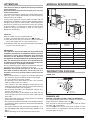 3
3
-
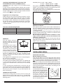 4
4
-
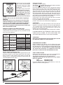 5
5
-
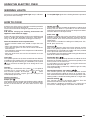 6
6
-
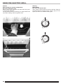 7
7
-
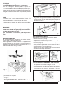 8
8
-
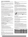 9
9
-
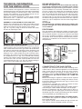 10
10
-
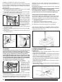 11
11
-
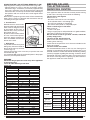 12
12
-
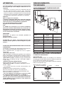 13
13
-
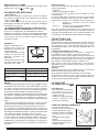 14
14
-
 15
15
-
 16
16
-
 17
17
-
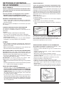 18
18
-
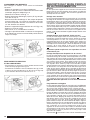 19
19
-
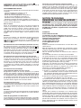 20
20
-
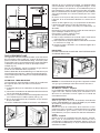 21
21
-
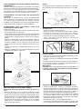 22
22
-
 23
23
-
 24
24
-
 25
25
-
 26
26
-
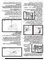 27
27
-
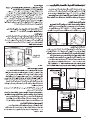 28
28
-
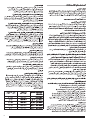 29
29
-
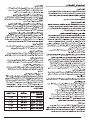 30
30
-
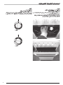 31
31
-
 32
32
-
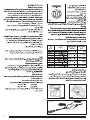 33
33
-
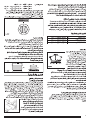 34
34
-
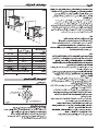 35
35
-
 36
36


Electrolux EKG90115W Manuel utilisateur
- Catégorie
- Cuisine
- Taper
- Manuel utilisateur
dans d''autres langues
- English: Electrolux EKG90115W User manual
Documents connexes
Autres documents
-
Indesit K3M11(W)/EX Mode d'emploi
-
Candy CMM662SKHTM/1 Le manuel du propriétaire
-
Zanussi Z9050G Manuel utilisateur
-
Zanussi ZCG664GX Manuel utilisateur
-
Whirlpool ACM 244/BL Mode d'emploi
-
-
Zonet ZUH2214L - REV 01 Instructions For Use Manual
-
-
-
ELICA 51613707 Fiche technique