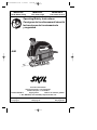
Skil 4680 Manuel utilisateur
- Catégorie
- Outils électroportatifs
- Taper
- Manuel utilisateur
Ce manuel convient également à

Operating/Safety Instructions
Consignes de fonctionnement/sécurité
Instrucciones de funcionamiento
y seguridad
4680
IMPORTANT: IMPORTANT : IMPORTANTE:
Read Before Using Lire avant usage Leer antes de usar
Consumer Information
Renseignement des consommateurs
Información para el consumidor
Toll Free Number: Appel gratuit : Número de teléfono gratuito:
1-877-SKIL999 (1-877-754-5999) http://www.skil.com
For English Parlez-vous français? ¿Habla español?
See page 2 Voir page 15 Ver página 28
SM 2610916643 2-04 2/24/04 1:50 PM Page 1

-2-
Work Area
Keep your work area clean and well lit.
Cluttered benches and dark areas invite
accidents.
Do not operate power tools in explosive
atmospheres, such as in the presence of
flammable liquids, gases, or dust. Power
tools create sparks which may ignite the dust
or fumes.
Keep by-standers, children, and visitors
away while operating a power tool.
Distractions can cause you to lose control.
Electrical Safety
Double Insulated tools are equipped with a
polarized plug (one blade is wider than the
other.) This plug will fit in a polarized outlet
only one way. If the plug does not fit fully in
the outlet, reverse the plug. If it still does
not fit, contact a qualified electrician to
install a polarized outlet. Do not change
the plug in any way. Double Insulation
eliminates the need for the three wire
grounded power cord and grounded power
supply system. Before plugging in the tool, be
certain the outlet voltage supplied is within the
voltage marked on the nameplate. Do not use
“AC only” rated tools with a DC power supply.
Avoid body contact with grounded surfaces
such as pipes, radiators, ranges and
refrigerators. There is an increased risk of
electric shock if your body is grounded. If
operating the power tool in damp locations is
unavoidable, a Ground Fault Circuit Interrupter
must be used to supply the power to your tool.
Electrician’s rubber gloves and footwear will
further enhance your personal safety.
Don't expose power tools to rain or wet
conditions. Water entering a power tool will
increase the risk of electric shock.
Do not abuse the cord. Never use the cord
to carry the tools or pull the plug from an
outlet. Keep cord away from heat, oil, sharp
edges or moving parts. Replace damaged
cords immediately. Damaged cords increase
the risk of electric shock.
When operating a power tool outside, use
an outdoor extension cord marked "W-A"
or "W." These cords are rated for outdoor use
and reduce the risk of electric shock. Refer to
“Recommended sizes of Extension Cords” in
the Accessory section of this manual.
Personal Safety
Stay alert, watch what you are doing and
use common sense when operating a
power tool. Do not use tool while tired or
under the influence of drugs, alcohol, or
medication. A moment of inattention while
operating power tools may result in serious
personal injury.
Dress properly. Do not wear loose clothing
or jewelry. Contain long hair. Keep your
hair, clothing, and gloves away from
moving parts. Loose clothes, jewelry, or long
hair can be caught in moving parts. Keep
handles dry, clean and free from oil and
grease.
Avoid accidental starting. Be sure switch is
“OFF” before plugging in. Carrying tools
with your finger on the switch or plugging in
tools that have the switch “ON” invites
accidents.
Remove adjusting keys or wrenches before
turning the tool “ON”. A wrench or a key
that is left attached to a rotating part of the
tool may result in personal injury.
Do not overreach. Keep proper footing and
balance at all times. Proper footing and
balance enables better control of the tool in
unexpected situations.
Use safety equipment. Always wear eye
protection. Dust mask, non-skid safety
shoes, hard hat, or hearing protection must be
used for appropriate conditions.
Tool Use and Care
Use clamps or other practical way to
secure and support the workpiece to a
stable platform. Holding the work by hand or
against your body is unstable and may lead to
loss of control.
Read and understand all instructions. Failure to follow all instructions
listed below, may result in electric shock, fire and/or serious personal injury.
SAVE THESE INSTRUCTIONS
!
WARNING
Power Tool Safety Rules
SM 2610916643 2-04 2/24/04 1:50 PM Page 2

-3-
Safety Rules for Jigsaws
Hold tool by insulated gripping surfaces
when performing an operation where the
cutting tool may contact hidden wiring or
its own cord. Contact with a "live" wire will
make exposed metal parts of the tool "live"
and shock the operator. Do not drill, fasten
or break into existing walls or other blind
areas where electrical wiring may exist. If
this situation is unavoidable, disconnect all
fuses or circuit breakers feeding this
worksite.
Never leave the trigger locked "ON".
Before plugging the tool in, check that the
trigger lock is "OFF". Accidental start-ups
could cause injury.
Be aware of the location and setting of
the switch "Lock-ON" button. If the switch
is locked "ON" during the use, be ready for
emergency situations to switch it "OFF", by
first pulling the trigger then immediately
releasing it without pressing the "Lock-ON"
button.
Keep hands away from cutting area. Do
not reach under the material being cut.
The proximity of the blade to your hand is
hidden from your sight.
Keep hands from between the gear
housing and saw blade holder. The
reciprocating blade holder can pinch your
fingers.
Do not use dull or damaged blades. Bent
blade can break easily or cause kickback.
Before starting to cut, turn tool "ON" and
allow the blade to come to full speed.
Tool can chatter or vibrate if blade speed is
too slow at beginning of cut and possibly
kickback.
Do not force tool. Use the correct tool for
your application. The correct tool will do the
job better and safer at the rate for which it is
designed.
Do not use tool if switch does not turn it
“ON” or “OFF”. Any tool that cannot be
controlled with the switch is dangerous and
must be repaired.
Disconnect the plug from the power
source before making any adjustments,
changing accessories, or storing the tool.
Such preventive safety measures reduce the
risk of starting the tool accidentally.
Store idle tools out of reach of children
and other untrained persons. Tools are
dangerous in the hands of untrained users.
Maintain tools with care. Keep cutting
tools sharp and clean. Properly
maintained tools, with sharp cutting edges
are less likely to bind and are easier to
control. Any alteration or modification is a
misuse and may result in a dangerous
condition.
Check for misalignment or binding of
moving parts, breakage of parts, and any
other condition that may affect the tools
operation. If damaged, have the tool
serviced before using. Many accidents are
caused by poorly maintained tools. Develop
a periodic maintenance schedule for your
tool.
Use only accessories that are
recommended by the manufacturer for
your model. Accessories that may be
suitable for one tool, may become
hazardous when used on another tool.
Service
Tool service must be performed only by
qualified repair personnel. Service or
maintenance performed by unqualified
personnel could result in a risk of injury. For
example: internal wires may be misplaced or
pinched, safety guard return springs may be
improperly mounted.
When servicing a tool, use only identical
replacement parts. Follow instructions in
the Maintenance section of this manual.
Use of unauthorized parts or failure to follow
Maintenance Instructions may create a risk
of electric shock or injury. Certain cleaning
agents such as gasoline, carbon
tetrachloride, ammonia, etc. may damage
plastic parts.
SM 2610916643 2-04 2/24/04 1:50 PM Page 3

-4-
Always wear safety goggles or eye
protection when using this tool. Use a
dust mask or respirator for applications
which generate dust.
Secure material before cutting. Never
hold it in your hand or across legs. Small
or thin material may flex or vibrate with the
blade, causing loss of control.
Make certain all adjusting screws and the
blade holder are tight before making a
cut. Loose adjusting screws and holders
can cause the tool or blade to slip and loss
of control may result.
When removing the blade from the tool
avoid contact with skin and use proper
protective gloves when grasping the
blade or accessory. Accessories may be
hot after prolonged use.
Some dust created by
power sanding, sawing,
grinding, drilling, and other construction
activities contains chemicals known to
cause cancer, birth defects or other
reproductive harm. Some examples of
these chemicals are:
• Lead from lead-based paints,
• Crystalline silica from bricks and cement
and other masonry products, and
• Arsenic and chromium from chemically-
treated lumber.
Your risk from these exposures varies,
depending on how often you do this type of
work. To reduce your exposure to these
chemicals: work in a well ventilated area,
and work with approved safety equipment,
such as those dust masks that are specially
designed to filter out microscopic particles.
!
WARNING
SM 2610916643 2-04 2/24/04 1:50 PM Page 4

-5-
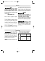
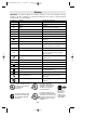
IMPORTANT: Some of the following symbols may be used on your tool. Please study them
and learn their meaning. Proper interpretation of these symbols will allow you to operate the
tool better and safer.
Symbol Name Designation/Explanation
V Volts Voltage (potential)
A Amperes Current
Hz Hertz Frequency (cycles per second)
W Watt Power
kg Kilograms Weight
min Minutes Time
s Seconds Time
Diameter Size of drill bits, grinding wheels, etc.
n
0
No load speed Rotational speed, at no load
.../min Revolutions or reciprocation per minute Revolutions, strokes, surface speed,
orbits etc. per minute
0 Off position Zero speed, zero torque...
1, 2, 3, ... Selector settings Speed, torque or position settings.
I, II, III, Higher number means greater speed
Infinitely variable selector with off Speed is increasing from 0 setting
Arrow Action in the direction of arrow
Alternating current Type or a characteristic of current
Direct current Type or a characteristic of current
Alternating or direct current Type or a characteristic of current
Class II construction Designates Double Insulated
Construction tools.
Earthing terminal Grounding terminal
Warning symbol Alerts user to warning messages
Ni-Cad RBRC seal Designates Ni-Cad battery recycling
program
Symbols
0
This symbol designates
that this tool is listed by
Underwriters Laboratories.
This symbol designates
that this tool is listed by
the Canadian Standards
Association.
This symbol designates
that this tool is listed to
Canadian Standards by
Underwriters Laboratories.
This symbol
designates
that
this tool
complies
to NOM
Mexican
Standards.
This symbol designates
that this tool is listed by
Underwriters Laboratories,
and listed to Canadian
Standards by Underwriters
Laboratories.
SM 2610916643 2-04 2/24/04 1:50 PM Page 5

-6-
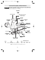
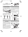
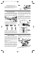
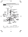
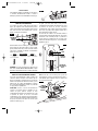
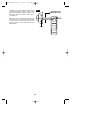
Functional Description and Specifications
Disconnect the plug from the power source before making any
assembly, adjustments or changing accessories. Such preventive safety
measures reduce the risk of starting the tool accidentally.
!
WARNING
MAXIMUM CAPACITIES
Model Blade Blade Stroke
No. Thickness Action Length Wood Aluminum Steel
4680 Minimum .7mm - Maximum 1.7mm Orbital/Scroll 13/16" 3-1/8" 1/2" 1/4"
NOTE: For tool specifications refer to the nameplate on your tool.
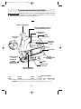
Jigsaws
VARIABLE SPEED
CONTROLLED
TRIGGER SWITCH
SCROLLING KNOB
FOOT
VENTILATION
OPENINGS
DUST PORT
/BLADE
STORAGE
COMPARTMENT
TOOL-LESS
BLADE CHANGE
COVER
ORBIT/SCROLLING
CONTROL LEVER
SITE-LIGHT™
LASER LIGHT/SITE-LIGHT™
CONTROL WHEEL
RUBBERIZED
GRIP
FIG.1
DUST
BLOWER
SWITCH
LASER LIGHT
ADJUSTMENT
SCREW
“LOCK-ON”
BUTTON
SM 2610916643 2-04 2/24/04 1:50 PM Page 6

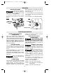
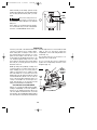
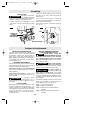
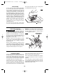
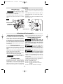
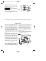
Attaching the Blade
To prevent personal injury,
always disconnect plug from
power source before assembling parts, making
adjustments, or changing blades.
1. Insert the saw blade (teeth in cutting
direction) until it latches in the plunger
(Fig. 2).
When inserting the saw blade, the back of
the blade must rest in the groove of the
guide roller (Fig. 3).
2. To remove blade, lift tool-less blade change
cover up with index finger and thumb and
remove blade.
For use with both T or U shank jigsaw blades.
-7-
Assembly
VARIABLE SPEED CONTROLLED
TRIGGER SWITCH
Your tool is equipped with a variable speed
trigger switch. The tool can be turned "ON" or
"OFF" by squeezing or releasing the trigger. The
speed can be adjusted from the minimum to
maximum nameplate SPM by the pressure you
apply to the trigger. Apply more pressure to
increase the speed and release pressure to
decrease speed (Fig. 1).
"LOCK-ON" BUTTON
The "Lock-ON" button, located in the handle
of your tool allows for continuous operation at
maximum SPM without holding the trigger
(Fig. 1).
TO LOCK TRIGGER "ON": squeeze trigger,
depress button and release trigger.
TO UNLOCK THE TRIGGER: squeeze trigger
and release it without depressing the "Lock-
ON" button.
If the “Lock-ON” button is
continuously being depressed,
the trigger can not be released.
PLUNGER SPEED
The stroke rate may be adjusted as described
earlier under “Variable Speed Controlled
Trigger Switch”. The best results for a
particular application is determined by
experience, though as a general rule, slower
speeds are for denser materials and faster
speeds are for soft materials.
LASER LIGHT/SITE-LIGHT™
CONTROL WHEEL
LASER RADIATION. AVOID
DIRECT EYE EXPOSURE.
DO NOT stare into the laser light source.
Never aim light at another person or object
other than the workpiece. Laser light can
damage your eyes.
DO NOT use tinted glasses
to enhance the laser light.
Tinted glasses will reduce overall vision for
the application and interfere with the normal
operation of the tool.
Never aim the beam at a
workpiece with a reflective
surface. Bright shiny reflective sheet steel or
similar reflective surfaces are not
recommended for laser use. Reflective
surfaces could direct the beam back toward
the operator.
The 4 position control wheel allows you to
control the function of the lights. Below, lists
the function of each setting (Fig. 1).
Setting 1: Turns OFF all lights.
Setting 2: Turns ON only the Laser light.
Setting 3: Turns ON both the Laser light and
the Site-Light.
Setting 4: Turns ON only the Site-Light.
!
WARNING
!
WARNING
Operating Instructions
FIG. 2
FIG. 3
TOOL-LESS
BLADE CHANGE
COVER
ROLLER GUIDE
BLADE
DANGER
!
!
WARNING
!
WARNING
SM 2610916643 2-04 2/24/04 1:50 PM Page 7

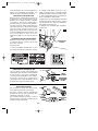
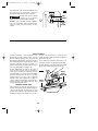
BLADE STORAGE COMPARTMENT
Your Jigsaw is equipped with a blade storage
compartment in the dust port of your saw
(Fig. 5) . To remove, pull compartment out of
dust port in direction of arrow.
Always make sure the blade storage
compartment is securely in the dust port to
prevent blades from falling out.
DUST EXTRACTION
Your jigsaw is equipped with a dust port for
dust and chip extraction.
To use this feature, remove blade storage
compartment and move dust blower switch to
the “OFF” position “O” (Fig. 6).
Attach vacuum hose (optional accessory) to
the dust port, and connect opposite end of the
hose to a shop vacuum cleaner.
BLADE
STORAGE
COMPARTMENT
FIG. 5
FIG. 6
DUST
PORT
DUST
BLOWER
SWITCH
DUST PORT
-8-
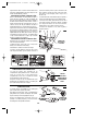
The laser light guide is a class IIIA laser with a
maximum output power of 5.0m Watts and
conforms to 21 CFR 1040.10 and 1040.11.
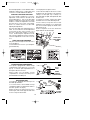
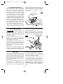
TO ADJUST THE LASER LINE GUIDE
Use a flat head screwdriver to turn the
adjustment screw located on the side of the
laser module (Fig. 4). Turn on the laser light
guide by rotating the control wheel to setting
number 2. Rotate the adjustment screw until
the laser line is in the center of the blade.
There is no need to turn the tool “ON” while
adjusting the light beam.
The Laser line guide has a limited amount of
travel. Do not continue to turn the adjustment
screw after the line stops moving or if it
becomes significantly harder to turn the
screw. Overturning the adjustment screw
may cause the adjustment system to break or
cause the adjustment screw to fall out of the
tool.
USING THE LASER LINE GUIDE
Only turn on the laser light on when the tool is
on the workpiece.
1. First mark the line of cut on your workpiece
(good side down.)
2. Insert plug into the power source.
3. Place the front edge of the saw foot on the
workpiece, turn the 4 position contol wheel to
setting 2 for laser light only or setting 3 for
laser light and site-light and align beam with
the line of cut .
4. Hold the tool firmly, squeeze the trigger
and allow the tool to reach desired speed.
5. Press down (to keep the saw foot flat
against the work surface) as you slowly push
the saw forward, keeping the beam in line
with the line of cut .
6. After completion of the cut, release the
trigger and turn off the laser light.
LASER LIGHT
ADJUSTMENT
SCREW
FIG. 4
SM 2610916643 2-04 2/24/04 1:50 PM Page 8

-9-
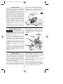
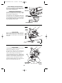
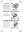
ORBITAL ACTION MODELS
Orbital Action models, have a lever (Fig. 8)
that will regulate the orbital action from
"Smooth" position for normal up and down
motion to maximum orbital action for faster
cutting in softer materials.
To increase orbital action, turn the lever to a
higher setting. To decrease orbital action turn
lever to a lower setting. When minimal
splintering is desired we recommend using
"Smooth" position.
SMOOTH LOW / MED FAST
MILD STEEL / SOFT METALS METAL PLASTIC SOFT WOODS
ALL MATERIALS HARD WOODS PLYWOOD
ATTENTION: In order to achieve orbital
action, the blade must be facing STRAIGHT
FORWARD and the back of the blade must
rest in the groove of the guide roller, and the
foot must be all the way in the forward
position. To adjust foot, lift foot adjustment
lever and flip lever completely over, then
push foot forward as far as possible and
lower foot adjustment lever to maintain
adjustment (Fig. 9).
Orbital cut control is not observable when
jigsaw is free running. Jigsaw must be
cutting for orbital action to occur. The speed
of cut is much more apparent in thicker
materials such as 2 by lumber.
SITE-LIGHT™
Your tool is also equipped with a light that
turns on automatically when the control wheel
is rotated to setting number 3 and 4, for
better visibility when cutting (Fig. 7).
FIG. 7
FIG. 8
ORBIT
CONTROL
LEVER
FOOT
BLADE
ROLLER
GUIDE
FOOT
ADJUSTMENT
LEVER
FIG. 9
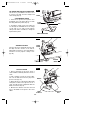
SCROLL MODELS
Scrolling saws permit 360˚ rotation of the
saw blade without turning the saw, so
intricate designs may be cut with minimum
effort. To permit rotation of plunger turn
lever, (Fig. 10) to scrolling. The plunger of
your scrolling saw can also be locked in (4)
positions, 90˚ apart.
ATTENTION: When scroll cutting the blade
must be moved away from the guide rollers.
(Always move foot completely back). To
adjust foot, lift foot adjustment lever and flip
lever completely over, then push foot
backwards as far as possible to engage
locking tab, then lower the foot adjustment
lever to maintain adjustment (Fig. 11).
Note: It may be necessary to turn scrolling
knob slightly back and forth to be sure the
plunger is locked in the desired position.
FIG. 10
LEVER
HANDLE
SCROLLING
KNOB
SM 2610916643 2-04 2/24/04 1:50 PM Page 9

-10-
Cutting Tips
Face the good side of the material down and
secure it in a bench vise or clamp it down.
Draw cutting lines or designs on the side of
the material facing up towards you. Then
place the front edge of the saw foot on the
work and line up the blade with the line to be
cut. Hold the jigsaw firmly, turn it on, and
press down (to keep the saw foot flat against
the work) as you slowly push the saw in the
direction of the cut.
Build up cutting rate gradually, cutting close
to the line (unless you want to leave stock for
finish sanding). As you cut you may have to
adjust or relocate the vise or clamps to keep
the work stable. Do not force the saw or the
blade teeth may rub and wear without cutting
and the blade may break. Let the saw do
most of the work. When following curves, cut
slowly so the blade can cut through cross
grain. This will give you an accurate cut and
will prevent the blade from wandering.
CUTTING WITH A STRAIGHTEDGE
Always use a rough cut blade when possible.
Clamp a straightedge on the work parallel to
the line of cut and flush with the side of the
saw foot. (Either first mark the line of cut and
then position the straightedge parallel and at
the same distance as between the blade and
the side edge of the foot or first mark the side
edge of the foot and then clamp the
straightedge on the mark and parallel to the
cut line Fig. 12).
On models with the scroll feature, it is
advised to lock scroller knob.
As you cut, keep the saw foot edge flush
against the straightedge and flat on the
workpiece (Fig. 12).
LINE
OF
CUT
FOOT
AGAINST
STRAIGHT-
EDGE
CLAMPS
FIG. 12
When manually scroll cutting, operate saw by
holding the handle with one hand and rotating
the scrolling knob manually with your free
hand.
Excessive side pressure to
the blade could result in
broken blades and/or damage to the material
being cut.
Note: When scroll cutting intricate designs,
we recommend using a scroll cutting blade.
However, a standard blade can be used.
!
CAUTION
FOOT
BLADE
ROLLER
GUIDE
FIG. 11
SM 2610916643 2-04 2/24/04 1:50 PM Page 10

-11-
METAL CUTTING
When cutting metal clamp material down. Be
extra certain that you move the saw along
slowly. Use lower speeds. Do not twist, bend,
or force the blade. If the saw jumps or
bounces, use a blade with finer teeth. If the
blade seems clogged when cutting soft metal,
use a blade with coarser teeth.
For easier cutting, lubricate the blade with a
stick of cutting wax, if available, or cutting oil
when cutting steel. Thin metal should be
sandwiched between two pieces of wood or
tightly clamped on a single piece of wood
(wood on top of the metal). Draw the cut lines
or design on the top piece of wood.
When cutting aluminum extrusion or angle
iron, clamp the work in a bench vise and saw
close to the vise jaws.
When sawing tubing and the diameter is
larger than the blade is deep, cut through the
wall of the tubing and then insert the blade
into the cut rotating the tube as you saw.
BEVEL OR ANGLE CUTTING
To prevent damage to the
tool when bevel or angle
cutting, the scroll mechanism must be locked
in place with the cutting edge of the blade
facing the front of the tool.
Disconnect the cord from the power source.
The foot can be adjusted to cut any angle
from 0˚ to 45,˚ and is equipped with quick
reference detent stops at 0˚, 15˚, 30˚, and 45˚.
TO ADJUST: Lift foot adjustment lever in the
bottom of foot as shown, move foot slightly
backward to disengage the locking tab
(Fig. 14).
Position foot to desired angle, then push
forward to engage locking tab and lower
adjustment lever to maintain adjustment. After
adjusting foot make a sample cut to check
the angle, (Fig. 14).
Note: If the foot becomes loose you can use
a screwdriver to tighten screw located on the
foot adjustment lever, then re-adjust the foot
adjustment lever.
!
WARNING
FOOT
ADJUSTMENT
LEVER
FIG. 14
PLUNGE CUTTING
Plunge cutting is useful and time-saving in
making rough openings in softer materials. It
is not necessary to drill a hole for an inside or
pocket cut. Draw lines for the opening, hold
the saw firmly, tilt it forward so that the toe of
the saw foot rests on the work, but with the
blade well clear of the work. Start the motor,
and then very gradually lower the blade.
When it touches, continue pressing down on
the toe of the saw foot slowly pivoting the
saw like a hinge until the blade cuts through
and the foot rests flat on the work. Then saw
ahead on the line of cut line. We do not
recommend plunge cutting with a scroll blade
(Fig. 13).
To make sharp corners, cut up to the corner,
then back up slightly before rounding the
corner. After the opening is complete, go
back to each corner and cut it from the
opposite direction to square it off. Do not try
to plunge cut into hard materials such as
steel.
TOE OF FOOT
LOCKING
TAB
FIG. 13
SCREW
FOOT
SM 2610916643 2-04 2/24/04 1:50 PM Page 11

-12-
STRAIGHT CUTTING
Once the rip fence is attached, measure from
the edge of work to the line of cut, and set
edge guide of rip fence to the same distance
and then securely tighten clamp screw
(Fig. 16).
DESIRED
WIDTH
CLAMP
SCREW
LINE OF CUT
RIP FENCE AND CIRCLE CUTTING GUIDE
This accessory is available at an extra cost. It
is used for fast and accurate straight and
circle cutting (Fig. 15).
ATTACHING RIP FENCE
1. Insert bar of rip fence through the slots
provided in foot, from either side of foot with
the edge guide facing down (Fig. 15).
2. Thread the clamp screw from under the
foot through the threaded hole in the clamp
on left side of foot, and securely tighten
clamp screw with a screwdriver, to clamp the
rip fence bar in place.
EDGE GUIDE DOWN
BAR
CLAMP
SCREW
SLOT
CLAMP
CIRCLE CUTTING
1. Before attaching the rip fence, draw a
circle and drive a finishing nail in the center of
circle.
2. Drill or plunge cut near the circles edge,
turn saw off and disconnect the plug from
power source (Fig. 17).
3. Attach rip fence to saw with the edge guide
facing UP. In order for the rip fence to cut a
circle, the nail must be in alignment with the
blade, as shown in (Fig. 18).
4. Measure the distance from the selected
hole to the blade to be equal to the circle
radius.
WEDGE
FINISHING
NAIL
EDGE
GUIDE UP
FIG. 15
FIG. 16
FIG. 17
SM 2610916643 2-04 2/24/04 1:50 PM Page 12

-13-
5. Insert plug into power source, hold the saw
firmly, squeeze trigger and slowly push the
saw forward. To make a hole, cut from inside
the circle; To make wheels or discs, cut from
the outside.
Cutting Tip: Cut slowly so the blade will stay
straight in the cut. Place small wedges in the
cut as shown in Fig. 17, to keep the inner
circle from spreading when near the end of
the cut.
BLADE MUST BE IN
ALIGNMENT WITH NAIL
NAIL
FIG. 18
SM 2610916643 2-04 2/24/04 1:50 PM Page 13

-14-
Service
Preventive maintenance
performed by unauth-
orized personnel may result in misplacing
of internal wires and components which
could cause serious hazard. We
recommend that all tool service, including
service of laser, be performed by a Skil
Factory Service Center or Authorized Skil
Service Station.
TOOL LUBRICATION
Your Skil tool has been properly lubricated
and is ready to use. It is recommended that
tools with gears be regreased with a special
gear lubricant at every brush change.
CARBON BRUSHES
The brushes and commutator in your tool
have been engineered for many hours of
dependable service. To maintain peak
efficiency of the motor, we recommend
every two to six months the brushes be
examined. Only genuine Skil replacement
brushes specially designed for your tool
should be used.
BEARINGS
After about 300-400 hours of operation, or at
every second brush change, the bearings
should be replaced at Skil Factory Service
Center or Authorized Skil Service Station.
Bearings which become noisy (due to heavy
load or very abrasive material cutting) should
be replaced at once to avoid overheating or
motor failure.
Cleaning
To avoid accidents always
disconnect the tool from
the power supply before cleaning or
performing any maintenance. The tool may
be cleaned most effectively with
compressed dry air. Always wear safety
goggles when cleaning tools with
compressed air.
Ventilation openings and switch levers must
be kept clean and free of foreign matter. Do
not attempt to clean by inserting pointed
objects through openings.
Certain cleaning agents
and solvents damage
plastic parts. Some of these are: gasoline,
carbon tetrachloride, chlorinated cleaning
solvents, ammonia and household
detergents that contain ammonia.
!
WARNING
!
WARNING
Maintenance
!
CAUTION
Accessories
If an extension cord is
necessary, a cord with
adequate size conductors that is capable
of carrying the current necessary for your
tool must be used. This will prevent
excessive voltage drop, loss of power or
overheating. Grounded tools must use 3-
wire extension cords that have 3-prong
plugs and receptacles.
NOTE: The smaller the gauge number, the
heavier the cord.
RECOMMENDED SIZES OF EXTENSION CORDS
120 VOLT ALTERNATING CURRENT TOOLS
!
WARNING
Tool’s
Ampere
Rating
Cord Size in A.W.G.
Wire Sizes in mm
2
3-6
6-8
8-10
10-12
12-16
18 16 16 14 0.75 0.75 1.5 2.5
18 16 14 12 0.75 1.0 2.5 4.0
18 16 14 12 0.75 1.0 2.5 4.0
16 16 14 12 1.0 2.5 4.0 —
14 12 — — — — — —
25 50 100 150 15 30 60 120
Cord Length in Feet Cord Length in Meters
SM 2610916643 2-04 2/24/04 1:50 PM Page 14

-15-
Vous devez lire et comprendre toutes les instructions. Le non-respect, même
partiel, des instructions ci-après entraîne un risque de choc életrique, d'incendie
et/ou de blessures graves.
CONSERVEZ CES INSTRUCTIONS
Règles de Sécurité Générales
AVERTISSEMENT
!
Aire de travail
Veillez à ce que l'aire de travail soit propre et bien
éclairée. Le désordre et le manque de lumière
favorisent les accidents.
N'utilisez pas d'outils électriques dans une
atmosphère explosive, par exemple enprésence de
liquides, de gaz ou de poussières inflammables. Les
outils électriques créent des étincelles qui pourraient
enflammer les poussières ou les vapeurs.
Tenez à distance les curieux, les enfants et les
visiteurs pendant que vous travaillez avec un outil
électrique. Ils pourraient vous distraire et vous faire
faire une fausse manoeuvre.
Sécurité électrique
Les outils à double isolation sont équipés d'une fiche
polarisée (une des lames est pluslarge que l'autre),
qui ne peut se brancher que d'une seule façon dans
une prise polarisée. Si la fiche n'entre pas
parfaitement dans la prise, inversez sa position ; si
elle n'entre toujours pasbien, demandez à un
électricien qualifié d'installer une prise de courant
polarisée. Ne modifiez pas la fiche de l'outil. La
double isolation élimine le besoin d'un cordon
d'alimentationà trois fils avec mise à la terre ainsi que
d'une prise de courant mise à la terre.
Avant de
brancher l'outil, assurez-vous que la tension de la prise
correspond, à celle indiquée sur la plaque signalétique.
N'utilisez pas d'outils prévus pour courant alternatif
seulement avec une source de courant continu.
Évitez tout contact corporel avec des surfaces mises à
la terre (tuyauterie, radiateurs, cuisinières,
réfrigérateurs, etc.). Le risque de choc électrique est
plus grand si votre corps est encontact avec la terre.
Si
l'utilisation de l'outil électrique dans un endroit humide
est inévitable, un disjoncteur de fuite à la terre doit être
utilisé pour alimenter votre outil. Des chaussures et des
gants en caoutchouc d'électricien contribueront à
accroître davantage votre sécurité personnelle.
N'exposez pas les outils électriques à la pluie ou à
l'eau. La présence d'eau dans un outil électrique
augmente le risque de choc électrique.
Ne maltraitez pas le cordon. Ne transportez pas l'outil
par son cordon et ne débranchez pas la fiche en tirant
sur le cordon. N'exposez pas le cordon à la chaleur, à
des huiles, à des arêtes vives ou à des pièces en
mouvement. Remplacez immédiatement un cordon
endommagé. Un cordon endommagé augmente le
risque de choc électrique.
Lorsque vous utilisez un outil électrique à l'extérieur,
employez un prolongateur pour l'extérieur marqué «
W-A » ou « W ». Ces cordons sont faits pour être
utilisés à l'extérieur et réduisent le risque de choc
électrique. Reportez-vous aux « Dimensions
recommandées des cordons de rallonge » dans la
section Accessoires de ce manuel.
Sécurité des personnes
Restez alerte, concentrez-vous sur votre travail et
faites preuve de jugement. N'utilisez pas un outil
électrique si vous êtes fatigué ou sous l'influence de
drogues, d'alcool ou de médicaments. Un instant
d'inattention suffit pour entraîner des blessures graves.
Habillez-vous convenablement. Ne portez ni
vêtements flottants ni bijoux. Confinez les cheveux
longs. N'approchez jamais les cheveux, les
vêtements ou les gants des pièces en mouvement.
Des vêtements flottants, des bijoux ou des cheveux
longs risquent d'être happés par des pièces en
mouvement. Gardez les poignées sèches, propres et
exemptes d'huile et de graisse.
Méfiez-vous d'un démarrage accidentel. Avant de
brancher l'outil, assurez-vous que son interrupteur est
sur ARRÈT. Le fait de transporter un outil avec le doigt
sur la détente ou de brancher un outil dont l'interrupteur
est en position MARCHE peut mener tout droit à un
accident.
Enlevez les clés de réglage ou de serrage avant de
démarrer l'outil. Une clé laissée dans une pièce
tournante de l'outil peut provoquer des blessures.
Ne vous penchez pas trop en avant. Maintenez un bon
appui et restez en équilibre entout temps. Un bonne
stabilité vous permet de mieux réagir à une situation
inattendue.
Utilisez des accessoires de sécurité. Portez toujours
des lunettes ou une visière. Selon les conditions,
portez aussi un masque antipoussière, des bottes de
sécurité antidérapantes, un casque protecteur et/ou un
appareil antibruit.
Utilisation et entretien des outils
Immobilisez le matériau sur une surface stable au
moyen de brides ou de toute autre façon adéquate. Le
fait de tenir la pièce avec la main ou contre votre corps
SM 2610916643 2-04 2/24/04 1:50 PM Page 15

-16-
Tenez l'outil par les surfaces isolées de préhension
en exécutant une opération au cours de laquelle
l'outil de coupe peut venir en contact avec les fils
cachés ou son propre cordon. Le contact avec un fil
sous tension rendra les pièces métalliques exposées
de l'outil sous tension et causera des chocs à
l'opérateur.
Ne percez, fixez et ne rentrez pas dans
des murs existants ou autres endroits aveugles
pouvant abriter des fils électriques. Si cette situation
est inévitable, débranchez tous les fusibles ou les
disjoncteurs alimentant ce site.
Ne tenez jamais la gâchette bloquée en position de
marche. Avant de brancher l'outil, assurez-vous que
le blocage de la gâchette est inhibé. Les mises en
marche accidentelles peuvent causer des blessures.
Soyez au courant de l'emplacement et de la
position du bouton de blocage en marche de la
gâchette. Si l'interrupteur est bloqué en marche
durant l'usage, soyez prêt, dans des cas d'urgence, à
le mettre à l'arrêt en appuyant d'abord sur la gâchette,
puis en la relâchant immédiatement sans appuyer sur
le bouton de blocage en marche.
Gardez les mains à l'écart de la zone de coupe. Ne
placez surtout pas la main sous le matériau que
vous coupez. Il est impossible de déterminer
exactement la proximité de la lame de votre main.
Évitez de vous placer les mains entre le carter
d'engrenages et le porte-lame de la scie. Le porte-
lame à mouvement alternatif risquerait de vous pincer
les doigts.
N'utilisez pas de lames émoussées ou
endommagées. Les lames pliées peuvent aisément
se fracturer ou causer un rebond.
Avant de commencer à couper, mettez l'outil en
marche et attendez que la lame atteigne sa vitesse
maximale. L'outil peut trembler ou vibrer si la vitesse
de la lame est trop lente au début de la coupe, et il
peut éventuellement rebondir.
Portez toujours des lunettes à coques latérales ou
des lunettes de protection en utilisant cet outil.
Utilisez un respirateur ou un masque anti-
poussières pour les applications produisant de la
poussière.
offre une stabilité insuffisante et peut amener un
dérapage de l'outil.
Ne forcez pas l'outil. Utilisez l'outil approprié à la
tâche. L'outil correct fonctionne mieux et de façon plus
sécuritaire. Respectez aussi la vitesse de travail qui lui
est propre.
N'utilisez pas un outil si son interrupteur est bloqué.
Un outil que vous ne pouvez pas commander par son
interrupteur est dangereux et doit être réparé.
Débranchez la fiche de l'outil avant d'effectuer un
réglage, de changer d'accessoire oude ranger l'outil.
De telles mesures préventives de sécurité réduisent le
risque de démarrage accidentel de l'outil.
Rangez les outils hors de la portée des enfants et
d'autres personnes inexpérimentées. Les outils sont
dangereux dans les mains d'utilisateurs novices.
Prenez soin de bien entretenir les outils. Les outils de
coupe doivent être toujours bien affûtés et propres.
Des outils bien entretenus, dont les arêtes sont bien
tranchantes, sont moins susceptibles de coincer et plus
faciles à diriger.Toute altération ou modification
constitue un usage erroné et peut causer un danger.
Soyez attentif à tout désalignement ou coincement
des pièces en mouvement, à tout bris ou à toute autre
condition préjudiciable au bon fonctionnement de
l'outil. Si vous constatez qu'un outil est endommagé,
faites-le réparer avant de vous en servir. De
nombreux accidents sont causés par des outils en
mauvais état. Élaborez un calendrier d'entretien
périodique de votre outil.
N'utilisez que des accessoires que le fabricant
recommande pour votre modèle d'outil. Certains
accessoires peuvent convenir à un outil, mais être
dangereux avec un autre.
Réparation
La réparation des outils électriques doit être confiée
à un réparateur qualifié. L'entretien ou la réparation
d'un outil électrique par un amateur peut avoir des
conséquences graves. Ainsi, des fils internes peuvent
être mal placés ou pincés, des ressorts de rappel de
protecteur peuvent être montés erronément.
Pour la réparation d'un outil, n'employez que des
pièces de rechange d'origine. Suivez les directives
données à la section « Réparation » de ce manuel.
L'emploi de pièces non autorisées ou le non-respect
des instructions d'entretien peut créer un risque de
choc électrique ou de blessures. Certains agents
nettoyants tels qu'essence, tétrachlorure de carbone,
ammoniac, etc., peuvent abîmer les pièces en plastique.
Règles de sécurité concernant les scies sauteuses
SM 2610916643 2-04 2/24/04 1:50 PM Page 16

-17-
Il importe de bien assujettir la pièce sur laquelle
vous travaillez. Ne la tenez jamais dans votre main
ou sur vos jambes. Les pièces minces et plus petites
peuvent fléchir ou vibrer avec la lame, risquant ainsi
de vous faire perdre le contrôle.
Avant de commencer à scier, assurez-vous que
toutes les vis de réglage et que le porte-lame sont
serrés. Les vis de réglage et porte-lame lâches
peuvent faire glisser l'outil ou la lame et ainsi vous
faire perdre le contrôle.
En retirant la lame de l'outil, évitez le contact avec
la peau et utilisez des gants protecteurs appropriés
en saisissant la lame ou l'accessoire. Les
accessoires peuvent être chauds après un usage
prolongé.
Les travaux à la machine
tel que ponçage, sciage,
meulage, perçage et autres travaux du bâtiment
peuvent créer des poussières contenant des produits
chimiques qui sont des causes reconnues de cancer,
de malformation congénitale ou d’autres problèmes
reproductifs. Ces produits chimiques sont, par
exemple :
• Le plomb provenant des peintures à base de plomb,
• Les cristaux de silices provenant des briques et du
ciment et d’autres produits de maçonnerie, et
• L’arsenic et le chrome provenant des bois traités
chimiquement.
Le niveau de risque dû à cette exposition varie avec la
fréquence de ces types de travaux. Pour réduire
l’exposition à ces produits chimiques, il faut travailler
dans un lieu bien ventilé et porter un équipement de
sécurité approprié tel que certains masques à poussière
conçus spécialement pour filtrer les particules
microscopiques.
AVERTISSEMENT
!
SM 2610916643 2-04 2/24/04 1:50 PM Page 17

-18-
Symboles
IMPORTANT : Certains des symboles suivants peuvent être utilisés sur votre outil. Veuillez les étudier et
apprendre leur signification. Une interprétation appropriée de ces symboles vous permettra d'utiliser l'outil de
façon plus efficace et plus sûre.
Symbole Nom Désignation/Explication
V Volts Tension (potentielle)
A Ampères Courant
Hz Hertz Fréquence (cycles par seconde)
W Watt Puissance
kg Kilogrammes Poids
min Minutes Temps
s Secondes Temps
Diamètre Taille des mèches de perceuse, meules,
etc.
n
0
Vitesse à vide Vitesse de rotation, à vide
.../min Tours ou mouvement alternatif par Tours, coups, vitesse en surface, orbites,
minute etc., par minute.
0 Position d'arrêt Vitesse zéro, couple zéro ...
1, 2, 3, ... Réglages du sélecteur Réglages de vitesse, de couple ou de
l, ll, lll, ... position. Un nombre plus élevé signifie
une vitesse plus grande.
Sélecteur variable à l'infini avec arrêt La vitesse augmente depuis le réglage 0
Flèche Action dans la direction de la flèche
Courant alternatif Type ou caractéristique du courant
Courant continu Type ou caractéristique du courant
Courant alternatif Type ou caractéristique du courant
ou continu
Construction classe II Désigne des outils construits avec double
isolation
Borne de terre Borne de mise à la terre
Symbole d'avertissement Alerte l'utilisateur aux messages
d'avertissement.
Sceau Ni-Cad RBRC™ Désigne le programme de recyclage des piles
Ni-Cad.
0
Ce symbole signifie que cet
outil est approuvé par
Underwriters Laboratories.
Ce symbole signifie que cet
outil est approuvé par
l'Association canadienne de
normalisation.
Ce symbole signifie que
cet outil est approuvé
conformément aux normes
canadiennes par Underwriters
Laboratories.
Ce symbole
signifie que
cet outil se
conforme aux
normes
mexicaines
NOM.
Ce symbole signifie que cet outil
est approuvé par Underwriters
Laboratories et qu’il a été
homologué selon les normes
canadiennes par Underwriters
Laboratories.
SM 2610916643 2-04 2/24/04 1:50 PM Page 18

-19-
Description fonctionnelle et spécifications
Débranchez la fiche de la prise de courant avant d'effectuer quelque assemblage
ou réglage que ce soit ou de changer les accessoires. Ces mesures de sécurité
préventive réduisent le risque d'une mise en marche accidentelle de l'outil.
AVERTISSEMENT
!
CAPACITÉS MAXIMALES
No. de Épaisseur Action de Longueur
modèle de lame la lame de la course Bois Aluminum Acier
4680 Minimum .7mm -Maximum 1.7mm Orbitale/chantournage 20 mm 80 mm 12 mm 6 mm
REMARQUE : Pour spécifications de l'outil, reportez-vous à la plaque signalétique de votre outil.
GÂCHETTE AVEC
VARIATION DE
VITESSE
POMMEAU DE CHANTOURNGE
SEMELLE
PRISES D’AIR
RACCORD
D’ASPIRATION/RANGEMENT
DES LAMES
COUVERCLE DU
SYSTÈME DE
CHANGEMENT DE
LAME SANS OUTIL
BOUTON DE BLOCAGE
EN MARCHE
LEVIER DE COMMANDE DE
L’ORBITE/CHANTOURNAGE
ÉCLAIRAGE D’APPOINT
SITE-LIGHT™
MOLETTE DE COMMANDE DU LASER ET DE
L’ÉCLAIRAGE D’APPOINT SITE-LIGHT™
POIGNÉE
CAOUTCHOUTÉE
INTERRUPTEUR DE
LA SOUFFLETTE
VIS DE RÉGLAGE
DU LASER
FIG.1
SM 2610916643 2-04 2/24/04 1:50 PM Page 19

-20-
Pose de la lame
Pour éviter le risque de bles-
sure, débranchez toujours le
cordon de la source d’alimentation avant d’effectuer les
réparations et réglages ou de remplacer les lames.
1. Insérez la lame de la scie (dents dans le sens de
coupe) jusqu'à ce qu'elle s'enclenche dans le plongeur
(Fig. 2).
Lorsque vous insérez la lame de la scie, le dos de la
lame doit reposer dans la rainure du rouleau de
guidage (Fig. 3).
2. Pour enlever la lame, soulevez le couvercle du
système de changement de lame sans outil avec le
pouce et l’index et enlevez la lame.
S’utilise avec des lames de scie sauteuse à queue soit
en T soit en U.
Assemblage
GÂCHETTE AVEC VARIATION DE VITESSE
Votre outil est doté d’un interrupteur à gâchette avec
variation de vitesse. Enfoncez ou relâchez la gâchette
pour démarrer ou arrêter l’outil. La vitesse peut être
réglée entre les valeurs mini et maxi indiquées à la
plaque signalétique en faisant varier la pression exercée
sur la gâchette. Plus la pression est élevée, plus la
vitesse est grande (Fig. 1).
BOUTON DE BLOCAGE EN MARCHE
Le bouton de blocage en marche situé sur la poignée de
votre outil permet de faire tourner celui-ci à la vitesse
maximale sans avoir à tenir la gâchette (Fig.1).
POUR BLOQUER LA GÂCHETTE EN POSITION MARCHE
(ON) : enfoncez la gâchette, appuyez sur le bouton et
relâchez la gâchette.
POUR DÉBLOQUER LA GÂCHETTE : appuyez sur la
gâchette et relâchez-la sans appuyer sur le bouton de
blocage en marche.
Si l’utilisateur appuie
continuellement sur le
bouton de blocage en marche, la gâchette ne peut pas
être relâchée.
VITESSE DU PISTON
On peut régler la course comme décrit ci-dessus dans
la section « Gâchette avec variation de vitesse ». Les
meilleurs résultats pour une application particulière
sont déterminés par l'expérience, bien qu'en général,
les vitesses plus lentes soient destinées à des
matériaux plus denses et les vitesses plus rapides à
des matériaux mous.
MOLETTE DE COMMANDE DU LASER ET DE
L’ÉCLAIRAGE D’APPOINT SITE-LIGHT™
RAYON LASER. ÉVITEZ UNE
EXPOSITION DIRECTE DES YEUX.
NE regardez PAS directement la source de lumière
laser. Ne dirigez jamais la lumière vers autrui ou
vers un objet autre que la pièce. La lumière laser
risque d’abîmer les yeux.
N’utilisez PAS de lunettes
teintées pour renforcer la
lumière laser. Les verres teintés réduisent la visibilité
générale et gênent l’utilisation normale de l’outil.
Ne dirigez jamais le
faisceau vers une pièce
dont la surface est réfléchissante. La tôle d’acier
brillante réflective ou les surfaces réflectives similaires
ne sont pas recommandées pour utilisation d’un laser.
Les surfaces réflectives risquent de rediriger le faisceau
vers l’utilisateur.
La molette de commande à 4 positions vous permet de
choisir le type d’éclairage. La liste des fonctions de
chaque réglage se trouve ci-dessous (Fig. 1).
Réglage 1 : Éteint toutes les lumières
Réglage 2 : Allume seulement le laser
Réglage 3 : Allume le laser et la lumière d’appoint
Site-Light
Réglage 4 : Allume seulement la lumière d’appoint
Site-Light.
Consignes de fonctionnement
AVERTISSEMENT
!
AVERTISSEMENT
!
FIG. 2
COUVERCLE DU
SYSTÈME DE
CHANGEMENT DE
LAME SANS OUTIL
FIG. 3
LAME
ROULEAU DE GUIDAGE
AVERTISSEMENT
!
AVERTISSEMENT
!
DANGER
!
SM 2610916643 2-04 2/24/04 1:50 PM Page 20
La page charge ...
La page charge ...
La page charge ...
La page charge ...
La page charge ...
La page charge ...
La page charge ...
La page charge ...
La page charge ...
La page charge ...
La page charge ...
La page charge ...
La page charge ...
La page charge ...
La page charge ...
La page charge ...
La page charge ...
La page charge ...
La page charge ...
La page charge ...
La page charge ...
La page charge ...
La page charge ...
La page charge ...
-
 1
1
-
 2
2
-
 3
3
-
 4
4
-
 5
5
-
 6
6
-
 7
7
-
 8
8
-
 9
9
-
 10
10
-
 11
11
-
 12
12
-
 13
13
-
 14
14
-
 15
15
-
 16
16
-
 17
17
-
 18
18
-
 19
19
-
 20
20
-
 21
21
-
 22
22
-
 23
23
-
 24
24
-
 25
25
-
 26
26
-
 27
27
-
 28
28
-
 29
29
-
 30
30
-
 31
31
-
 32
32
-
 33
33
-
 34
34
-
 35
35
-
 36
36
-
 37
37
-
 38
38
-
 39
39
-
 40
40
-
 41
41
-
 42
42
-
 43
43
-
 44
44


Skil 4680 Manuel utilisateur
- Catégorie
- Outils électroportatifs
- Taper
- Manuel utilisateur
- Ce manuel convient également à
dans d''autres langues
- English: Skil 4680 User manual
- español: Skil 4680 Manual de usuario
Documents connexes
-
Skil JS314901 Le manuel du propriétaire
-
Skil 4495-02 Manuel utilisateur
-
-
-
-
-
-
-
Skil JS820301 Le manuel du propriétaire
-