Sauder 409064 Assembly Instructions Manual
- Taper
- Assembly Instructions Manual

04 / 26 / 13
Lot #: 352741
Date Purchased:
409064
Assembly Instructions
Instructions d’assemblage
Instrucciones de Ensamblaje
DO NOT RETURN YOUR UNIT TO THE STORE
Contact us first
NE PAS RAPPORTER L’ÉLÉMENT AU MAGASIN
Nous contacter en premier
NO DEVUELVA SU UNIDAD A LA TIENDA
Comuníquese con nosotros primero
This instruction booklet contains important safety information.
Please read and keep for future reference.
NOTE
Este folleto de instrucciones contiene información importante sobre la seguridad.
Por favor lea y guárdelo para referencia en el futuro.
NOTA
Ce manuel d’instructions contient d’importantes informations relatives à la sécurité.
À lire et conserver pour toute référence future.
REMARQUE
www.sauder.com
For immediate service, our website is available
24 hours a day, 7 days a week
to order replacement parts, access assembly tips,
register your product, and view Sauder products.
Most replacement parts ship from our
facility in one or two business days.
Les pièces de rechange sont, pour la plupart, expédiées de
notre établissement dans les un à deux jours ouvrables.
La mayoría de piezas de repuesto son enviadas desde
nuestra instalación en uno o dos días laborables.
Mon-Fri -- 9am-5:30pm ET
United States and Canada (except holidays)
Consumer Services 1--800--523--3987
register your new purchase online
www.sauder.com
Mobile Lifestyle Center
Meuble mobile Lifestyle
Mueble móvil Lifestyle
Pour obtenir une service immédiate, notre site Internet
est disponible 24 heures sur 24, 7 jours sur 7,
pour commander des pièces de rechange,
des conseils d’assemblage, enregistrer tout produit
ou visualiser des produits Sauder.
Du lundi au vendredi de9h00à17h30
(heure normale de l’est)
Aux États--Unis et au Canada (sauf jours fériés)
Services aux consommateurs 1--800--523--3987
Para el servicio inmediata, nuestro sitio Web está
disponible las 24 horas al día,
7 días a la semana para pedir piezas de repuesto,
consejos de ensamblaje, registrar su producto y
ver los productos Sauder.
De lunes a viernes de 9 a.m. a 5:30 p.m. (hora del este)
Estados Unidos y Canadá (salvo días festivos)
Servicios del consumidor 1--800--523--3987
The Edge Water Collection
La Collection Edge Water
La Colección Edge Water

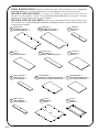
PARTS IDENTIFICATION: Each part for this unit may not have a label or inked letter on it. Use this PARTS
IDENTIFICATION page, the labels, and the inked letters to help distinguish similar parts from each other.
IDENTIFICATION DES PIÈCES : Les pièces de cet élément ne comportent peut--être pas toutes une
étiquette ou une lettre imprimée. Utiliser cette page IDENTIFICATION DES PIÈCES, les étiquettes et les lettres
imprimées pour faciliter l’identification des pièces semblables.
IDENTIFICACIÓN DE LAS PARTES: Cada pieza para esta unidad puede que no tenga una etiqueta o una
letra entintada. Use esta página IDENTIFICACIÓN DE LAS PARTES, etiquetas y las letras entintadas para ayudar
a identificar piezas similares.
409064
UPRIGHT -- 1
MONTANT -- 1
PARAL -- 1
RIGHT END -- 1
EXTRÉMITÉ DROITE -- 1
EXTREMO DERECHO -- 1
LEFT END -- 1
EXTRÉMITÉ GAUCHE -- 1
EXTREMO IZQUIERDO -- 1
A B C
BOTTOM -- 1
DESSOUS -- 1
FONDO -- 1
TOP -- 1
DESSUS -- 1
PANEL SUPERIOR -- 1
SMALL TOP -- 1
PETIT DESSUS -- 1
PANEL SUPERIOR PEQUEÑO -- 1
D E F
PRINTER SHELF -- 1
TABLETTE D’IMPRIMANTE -- 1
ESTANTE DE IMPRESORA -- 1
SMALL BOTTOM -- 1
PETIT DESSOUS -- 1
FONDO PEQUEÑO -- 1
LAPTOP SHELF -- 1
TABLETTE D’ORDINATEUR PORTATIF -- 1
ESTANTE DE COMPUTADOR PORTÁTIL -- 1
G H I
DOOR -- 2
PORTE -- 2
PUERTA -- 2
SMALL BACK -- 1
PETIT ARRIÈRE -- 1
DORSO PEQUEÑO -- 1
BACK -- 1
ARRIÈRE -- 1
DORSO -- 1
J K L

409064
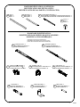
PARTS IDENTIFICATION (CONTINUED):
IDENTIFICATION DES PIÈCES (SUITE) :
IDENTIFICACIÓN DE LAS PARTES (CONTINUACIÓN):
LAPTOP SHELF MOLDING -- 1
MOULURE DE LA TABLETTE D’ORDINATEUR PORTATIF -- 1
MOLDURA DEL ESTANTE DE COMPUTADORA PORTÁTIL -- 1
LEG -- 2
PIED -- 2
PATA -- 2
MOLDING -- 2
MOULURE -- 2
MOLDURA -- 2
M N O
FOOT -- 2
PIED -- 2
PATA -- 2
P
HARDWARE IDENTIFICATION:
IDENTIFICATION DES PIÈCES DE QUINCAILLERIE :
IDENTIFICACIÓN DE HERRAJES:
EXTENSION SLIDE -- 2
COULISSE D’EXTENSION -- 2
CORREDERA DE EXTENSIÓN -- 2
R
EXTENSION RAIL -- 2
GLISSIÈRE D’EXTENSION -- 2
RIEL DE EXTENSIÓN -- 2
Q
TWIST-LOCK
R
FASTENER -- 3
FIXATION TWIST–LOCK
R
-- 3
SUJETADOR TWIST–LOCK
R
-- 3
S
HIDDEN CAM -- 18
EXCENTRIQUE ESCAMOTABLE -- 18
EXCÉNTRICO ESCONDIDO -- 18
1F
CAM SCREW -- 6
VIS D’EXCENTRIQUE -- 6
BIELA DE EXCÉNTRICO -- 6
8F
CAM DOWEL -- 12
CHEVILLE D’EXCENTRIQUE -- 12
PASADOR DE EXCÉNTRICO -- 12
2F
METAL PIN -- 6
GOUPILLE EN MÉTAL -- 6
ESPIGA DE METAL -- 6
X
METAL BRACKET -- 7
CONSOLE EN MÉTAL -- 7
SOPORTEDEMETAL--7
W
(EXTENSION SET SHOWN SEPARATED)
(ENSEMBLE DE EXTENSION ILLUSTRÉ À PART)
(JUEGO DE EXTENSIÓN MOSTRADO SEPARADO)

409064
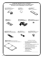
HARDWARE IDENTIFICATION (CONTINUED):
IDENTIFICATION DES PIÈCES DE QUINCAILLERIE (SUITE) :
IDENTIFICACIÓN DE HERRAJES (CONTINUACIÓN):
RAIL BRACKET -- 4
CONSOLE DE GLISSIÈRE -- 4
MÉNSULA DE RIEL -- 4
Y
HINGE -- 2
CHARNIÈRE -- 2
BISAGRA -- 2
BB
KNOB -- 2
POIGNÉE -- 2
TIRADOR -- 2
Z
BACKPLATE -- 2
FERRURE -- 2
PLACA DE TIRADOR -- 2
AA
DOOR HINGE -- 4
CHARNIÈRE DE PORTE -- 4
BISAGRA DE PUERTA -- 4
CC
CAM COVER -- 2
COUVERCLE D’EXCENTRIQUE -- 2
CUBIERTA DE EXCÉNTRICO -- 2
DD
FELT DISC CARD -- 1
FICHE DE TAMPONS EN FEUTRE - 1
TARJETA CON TOPES DE FIELTRO - 1
EE
WHEEL RUNNER -- 6
COULISSEAU À ROULETTES -- 6
RUEDA DE GIRO LIBRE -- 6
GG
CORD CLIP -- 3
CLIP DE CORDON -- 3
GRAPA DE CABLE -- 3
FF
LAPTOP PAD -- 1
TAPIS POUR ORDINATEUR PORTABLE -- 1
ALMOHADILLA PARA COMPUTADORA PORTÁTIL -- 1
HH
Certificate of Conformity
1. This certificate applies to the Sauder
Woodworking Product identified by this
Instruction Book.
2. This certificate applies to compliance of this
product with the CPSC Ban on
Lead--Containing Paint (16 CFR 1303).
3. This product is manufactured by:
Sauder Woodworking Company
502 Middle Street
Archbold, Ohio 43502
(419) 446--2711
4. Date of Manufacture: ________________

409064
BLACK 1--7/8” FLAT HEAD SCREW -- 2
VIS NOIRE TÊTE PLATE 48 mm -- 2
TORNILLO NEGRO DE CABEZA PERDIDA de 48 mm -- 2
BLACK 1--5/8” PAN HEAD SCREW -- 2
VIS NOIRE TÊTE GOUTTE DE SUIF 41 mm -- 2
TORNILLO NEGRO DE CABEZA REDONDA de 41 mm -- 2
1
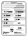
NOTE / REMARQUE / NOTA:
Using a SCREW that is too long will cause damage. Before beginning assembly, separate
each type of SCREW. Carefully study the SCREW diagrams below (SHOWN ACTUAL SIZE
).
Pay close attention to the color of each SCREW. You may receive extra hardware with your unit.
L’usage d’une VIS trop longue peut endommager l’élément. Avant de commencer l’assemblage, séparer chaque
type de VIS. Attentivement, réviser les schémas des VIS ci--dessous (VIS ILLUSTRÉES GRANDEUR NATURE
).
Faire attention à la couleur de chaque VIS. Il est possible que unes pièces supplémentaires sont incluses avec l’élément.
El uso de un TORNILLO demasiado largo causará daño. Antes de comenzar el ensamblaje, separe cada tipo de TORNILLO.
Atentamente estudie los diagramas de TORNILLO abajo (TORNILLOS MOSTRADOS EN TAMAÑO REAL
).
Preste cuidadosa atención al color de cada TORNILLO. Es posible que se incluyen unas piezas de herraje suplementarias
con la unidad.
II JJ
MM NN
OO PP
BLACK 1--1/8” MACHINE SCREW -- 2
VIS NOIRE À MÉTAUX 28 mm -- 2
TORNILLO NEGRO PARA METAL de 28 mm -- 2
BLACK 7/8” LARGE HEAD SCREW -- 4
VIS NOIRE TÊTE LARGE 22 mm -- 4
TORNILLO NEGRO DE CABEZA GRANDE de 22 mm -- 4
KK LL
BLACK 9/16” LARGE HEAD SCREW -- 30
VIS NOIRE TÊTE LARGE 14 mm -- 30
TORNILLO NEGRO DE CABEZA GRANDE de 14 mm -- 30
BLACK 1/2” FLAT HEAD SCREW -- 8
VIS NOIRE TÊTE PLATE 13 mm -- 8
TORNILLO NEGRO DE CABEZA PERDIDA de 13 mm -- 8
GOLD 5/16” FLAT HEAD SCREW -- 4
VIS DORÉE TÊTE PLATE 8 mm -- 4
TORNILLO DORADO DE CABEZA PERDIDA de 8 mm -- 4
NAIL -- 26
CLOU -- 26
CLAVO -- 26
ASSEMBLY TOOLS REQUIRED
OUTILS D’ASSEMBLAGE REQUIS
HERRAMIENTAS DE ENSAMBLAJE REQUERIDAS
TIP SHOWN ACTUAL SIZE
POINTE GRANDEUR NATURE
PUNTA MOSTRADA EN TAMAÑO REAL
HAMMER
MARTEAU
MARTILLO
NO. 2 PHILLIPS SCREWDRIVER
TOURNEVIS À TÊTE CRUCIFORME PHILLIPS n_2
DESTORNILLADOR PHILLIPS (CRUZ) No. 2

2
409064
H
www.sauder. com/services
S
Assembler l’élément sur un sol à
moquette ou sur le carton vide pour éviter
d’endommager l’élément ou le sol.
- Pour commencer l’assemblage,
enfoncer une FIXATION
TWIST--LOCK
R
SAUDER (S) dans les
gros trous dans la TABLETTE
D’ORDINATEUR PORTATIF (H).
REMARQUE
: Ne pas serrer les
FIXATIONS TWIST--LOCK
R
àcestade
de l’assemblage.
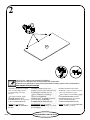
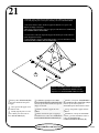
Assemble your unit on a carpeted
floor or on the empty carton to
avoid scratching your unit or
the floor.
- To begin assembly, push a
SAUDER TWIST-LOCK
R
FASTENER (S) into the large holes
in the LAPTOP SHELF (H).
NOTE
: Do not tighten the
TWIST-LOCK
R
FASTENERS at
this time.
Ensamble la unidad sobre un piso
alfombrado o sobre el cartón vacío para
evitar rayar la unidad o el piso.
- Para comenzar el ensamblaje, empuje
un SUJETADOR TWIST--LOCK
R
SAUDER (S) dentro de los agujeros
grandes del ESTANTE DE
COMPUTADOR PORTÁTIL (H).
NOTA
: No apriete los SUJETADORES
TWIST--LOCK
R
por ahora
Look for this icon. It means a video assembly tip is available at:
Repérer cette icône. Elle signifie qu’un conseil de montage vidéo est disponible à :
Busque este icono. Significa que un consejo práctico para ensamble de muebles, grabado en video, está disponible en:
www.sauder.com/services/tips

3
409064
www.sauder. com/services
(12 used)
(12 utilisées)
(12 utilizados)
Do not tighten the HIDDEN CAMS in this step.
Ne pas
serrer les EXCENTRIQUES ESCAMOTABLES à cette étape.
No
apriete los EXCÉNTRICOS ESCONDIDOS en este paso.
Insert the CAM DOWEL into the HIDDEN CAM.
Insérer la CHEVILLE D’EXCENTRIQUE dans
l’EXCENTRIQUE ESCAMOTABLE.
Inserte el PASADOR DE EXCÉNTRICO dentro
del EXCÉNTRICO ESCONDIDO.
Arrow
Flèche
Flecha
Arrow
Flèche
Flecha
- Enfoncer dix--huit EXCENTRIQUES
ESCAMOTABLES (1F) dans les
EXTRÉMITÉS (A et B), le
DESSOUS (F), le PETIT DESSOUS (G)
et le PETIT ARRIÈRE (J). Insérer ensuite
l’extrémité en métal d’une CHEVILLE
D’EXCENTRIQUE (2F) dans chaque
EXCENTRIQUE ESCAMOTABLE, à
l’exception des EXCENTRIQUES de le
chant long des EXTRÉMITÉS.
- Push eighteen HIDDEN
CAMS (1F) into the ENDS (A
and B), BOTTOM (F), SMALL
BOTTOM (G) and SMALL
BACK (J). Then, insert the metal
end of a CAM DOWEL (2F) into
each HIDDEN CAM, except for
the CAMS in the long edge of the
ENDS.
- Empuje dieciocho EXCÉNTRICOS
ESCONDIDOS (1F) dentro de los
EXTREMOS (A y B), del FONDO (F),
del FONDO PEQUEÑO (G) y del
DORSO PEQUEÑO (J). A continuación,
inserte el extremo en metal de un
PASADOR DE EXCÉNTRICO (2F)
dentro de cada EXCÉNTRICO
ESCONDIDO, menos en el borde largo de
los EXTREMOS.
Arrow
Flèche
Flecha
(18 used)
(18 utilisées)
(18 utilizados)
Do not insert CAM DOWELS (U)
into these edges.
Ne pas insérer les CHEVILLES
D’EXCENTRIQUE (U) dans ces
chants.
No inserte los PASADORES DE
EXCÉNTRICO (U) dentro de
estos bordes.
A
B
F
G
J
2F
1F
1F
2F

4
409064
www.sauder. com/services
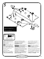
- Turn six CAM SCREWS (8F)
into the LEGS (M).
- Atornille seis BIELAS DE
EXCÉNTRICO (8F) dentro de las
PATAS (M).
- Faire tourner six VIS
D’EXCENTRIQUE (8F) dans les
PIEDS (M).
M
M
8F

5
409064
www.sauder. com/services
GG
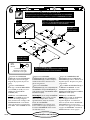
- With a hammer, gently tap six
WHEEL RUNNERS (GG) into the
ENDS (A and B).
NOTE
: Measure the height of your
printer. You have the choice of
mounting the RAIL BRACKETS
in three different height positions to
fit your printer. The three positions
will allow a clearance of 11”,
13 1/2” and 15”.
- Fasten four RAIL
BRACKETS (Y) to the ENDS (A
and B). Use eight BLACK 9/16”
LARGE HEAD SCREWS (MM).
- Con un martillo, suavemente con
pequeños golpes introduzca seis
RUEDAS DE GIRO LIBRE (GG) en los
EXTREMOS (A y B).
NOTA
: Mida la altura a su impresora.
Usted tiene la opción de montar los
SOPORTES DE RIEL en tres diferentes
posiciones de altura para fijar su
impresora. Las tres posiciones permitirán
una separación de 30 cm, 34 cm y 38 cm.
- Fije cuatro MÉNSULAS DE RIEL (Y)
a los EXTREMOS (A y B). Utilice ocho
TORNILLOS NEGROS DE CABEZA
GRANDE de 14 mm (MM).
- À l’aide d’un marteau, enfoncer
délicatement six COULISSEAUX À
ROULETTES (GG) dans les
EXTRÉMITÉS (A et B).
REMARQUE
: Mesurer la longueur de
l’imprimante. Les CONSOLES DE
GLISSIÈRES peuvent être montées à trois
hauteurs différentes pour convenir à
l’imprimante. Ces trois positions offriront
un dégagement de 30 cm, 34 cm et 38 cm.
- Fixer quatre CONSOLES DE
GLISSIÈRE (Y) aux EXTRÉMITÉS (A
et B). Utiliser huit VIS NOIRES TÊTE
LARGE 14 mm (MM).
Y
8usedinthisstep
8 utilisées à cette étape
8 utilizados en este paso
Black
Noire
Negro
MM
A
B
Use these holes for 15” printer clearance.
Utiliser ces trous pour avoir un
dégagement d’imprimante de 38 cm.
Utilice estos agujeros para la separación
de 38 cm de la impresora.

6
409064
www.sauder. com/services
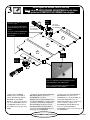
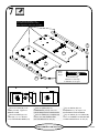
- Separate the EXTENSION
SLIDES (R) from the EXTENSION
RAILS (Q) as shown in the upper
diagram. Be prepared, the parts are
greasy.
- Fasten an EXTENSION
RAIL (Q) to the RAIL BRACKETS
on each END (A and B). Use four
GOLD 5/16” FLAT HEAD
SCREWS (OO).
NOTE
: For each EXTENSION
RAIL, turn a SCREW into the hole
shown in the enlarged diagram.
Then, slide the inner cartridge of the
EXTENSION RAIL out to find the
other hole that lines up with the hole
in the END. Turn a SCREW into this
hole.
- Separe las CORREDERAS DE
EXTENSIÓN (R) de los RIELES DE
EXTENSIÓN (Q) como se muestra en el
diagrama superior. Prepárese, las piezas
son grasientas.
- Fije un RIEL DE EXTENSIÓN (Q) a
las MÉNSULAS DE RIEL en cada
EXTREMO (A y B). Utilice cuatro
TORNILLOS DORADOS DE CABEZA
PERDIDA de 8 mm (OO).
NOTA
: Para cada RIEL DE
EXTENSIÓN, atornille un TORNILLO
dentro del agujero indicado en el
diagrama ampliado. A continuación
deslice el cartucho interno del RIEL DE
EXTENSIÓN hacia el exterior para
encontrar el otro agujero que se alinea con
el agujero del EXTREMO. Atornille un
TORNILLO dentro de este agujero.
- Séparer les COULISSES
D’EXTENSION (R) des GLISSIÈRES
D’EXTENSION (Q) comme l’indique le
schéma du haut. Faire attention car les
pièces sont graissées.
- Fixer une GLISSIÈRE
D’EXTENSION (Q) aux CONSOLES DE
GLISSIÈRE de chaque EXTRÉMITÉ (A
et B). Utiliser quatre VIS DORÉES TÊTE
PLATE 8 mm (OO).
REMARQUE
: Pour chaque GLISSIÈRE
D’EXTENSION, faire tourner une VIS
dans le trou indiqué dans le schéma
agrandi. Ensuite, enfiler la cartouche
internedelaGLISSIÈRE
D’EXTENSION vers l’extérieur pour
trouver l’autre trou qui est aligné sur le
trou dans l’EXTRÉMITÉ. Faire tourner
une VIS dans ce trou.
Push the black lever in and pull the SLIDE from the RAIL.
Appuyer le levier noir vers l’intérieur et tirer la COULISSE de la GLISSIÈRE.
Empuje la palanca negra hacia el interior y separe la CORREDERA del RIEL.
QR
Hole
Trou
Agujero
Open end
Extrémité ouverte
Extremo abierto
Open end
Extrémité ouverte
Extremo abierto
4usedinthisstep
4 utilisées à cette étape
4 utilizados en este paso
Gold
Dorée
Dorado
OO
A
B
Edge with HIDDEN CAMS
Chant avec les EXCENTRIQUES ESCAMOTABLES
Borde con EXCÉNTRICOS ESCONDIDOS
Edge with HIDDEN CAMS
Chant avec les EXCENTRIQUES ESCAMOTABLES
Borde con EXCÉNTRICOS ESCONDIDOS
Q
Q

7
409064
www.sauder. com/services
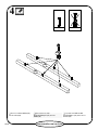
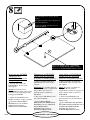
- Fasten the LEGS (M) to the
ENDS (A and B). Tighten six
HIDDEN CAMS.
- Fasten the FEET (P) to the
LEGS (M). Use two BLACK
1--5/8PANHEADSCREWS(JJ).
- Fije las PATAS (M) a los
EXTREMOS (A y B). Apriete seis
EXCÉNTRICOS ESCONDIDOS.
- Fije las PATAS (P) a las PATAS (M).
Utilice dos TORNILLOS NEGROS DE
CABEZA REDONDA de 41 mm (JJ).
- Fixer les PIEDS (M) aux
EXTRÉMITÉS (A et B). Serrer six
EXCENTRIQUES ESCAMOTABLES.
- Fixer les PIEDS (P) aux PIEDS (M).
Utiliser deux VIS NOIRES TÊTE
GOUTTE DE SUIF 41 mm (JJ).
M
M
A
B
2usedinthisstep
2 utilisées à cette étape
2 utilizados en este paso
Black
Noire
Negro
JJ
P
P
These surfaces should be even.
Ces surfaces devraient être à fleur.
Estas superficies deben estar niveladas.
1
2

8
409064
www.sauder. com/services
The unfinished area is closer to the top
surface.
La surface non finie se trouve plus près de
la surface supérieure.
El área sin acabado está más cerca a la
superficie superior.
How to use the SAUDER
TWIST-LOCK
R
FASTENER (Refer to the
enlarged
diagram.)
1. Insert the dowel end of the
FASTENER into the hole of the
adjoining part.
NOTE
: The dowel end of the
FASTENER must remain fully inserted
in the hole of the adjoining part while
locking the FASTENER.
2. Tighten the FASTENER with a
Phillips screwdriver as tight as possible.
- Fasten the LAPTOP SHELF
MOLDING (O) to the LAPTOP
SHELF (H). Tighten three
TWIST-LOCK
R
FASTENERS.
Cómo utilizar el SUJETADOR
TWIST--LOCK
R SAUDER
(Refiérase al diagrama ampliado.)
1. Inserte el extremo con cabilla del
SUJETADOR dentro del agujero de la
parte adjunta.
NOTA:
El extremo con cabilla del
SUJETADOR debe quedarse
completamente insertado en el agujero de
la parte adjunta cuando se enclava el
SUJETADOR.
2. Apriete el SUJETADOR lo más
apretado posible con un destornillador
Phillips (cruz).
- Fije la MOLDURA DEL ESTANTE
DE COMPUTADORA PORTÁTIL (O) al
ESTANTE DE COMPUTADORA
PORTÁTIL (H). Apriete tres
SUJETADORES TWIST--LOCK
R
.
Utilisation de la FIXATION
TWIST--LOCK
R SAUDER
(Consulter le schéma agrandi.)
1. Insérer l’extrémité filetée de la
FIXATION dans le trou de la pièce
attenante.
REMARQUE
: L’extrémité filetée de
la FIXATION doit rester complètement
inséréedansletroudelapièce
attenante lorsque l’on bloque la
FIXATION.
2. Bien serrer la FIXATION à l’aide
d’un tournevis Phillips.
- Fixer la MOULURE DE
TABLETTE POUR ORDINATEUR
PORTABLE (O) sur la TABLETTE
POUR ORDINATEUR
PORTABLE (H). Serrer trois
FIXATIONS TWIST--LOCK
R
.
H
O
Surface with TWIST-LOCK
R
FASTENERS
Surface avec les FIXATIONS TWIST--LOCKR
Superficie con SUJETADORES TWIST--LOCKR

9
www.sauder. com/services
2usedinthisstep
2 utilisées à cette étape
2 utilizados en este paso
Black
Noire
Negro
II
- Fasten the SMALL
BOTTOM (G) to the
UPRIGHT (C). Tighten two
HIDDEN CAMS.
- Fasten the SMALL BACK (J)
to the SMALL BOTTOM (G). Use
two BLACK 1--7/8” FLAT HEAD
SCREWS (II).
- Fije el FONDO PEQUEÑO (G) al
PARAL (C). Apriete dos EXCÉNTRICOS
ESCONDIDOS.
- Fije el DORSO PEQUEÑO (J) al
FONDO PEQUEÑO (G). Utilice dos
TORNILLOS NEGROS DE CABEZA
PERDIDA de 48 mm (II).
- Fixer le PETIT DESSOUS (G) au
MONTANT (C). Serrer deux
EXCENTRIQUES ESCAMOTABLES.
- Fixer le PETIT ARRIÈRE (J) au
PETIT DESSOUS (G). Utiliser deux VIS
NOIRES TÊTE PLATE 48 mm (II).
G
C
J
Large hole
Grand trou
Agujero grande
Surface with HIDDEN CAMS
Surface avec les EXCENTRIQUES ESCAMOTABLES
Superficie con EXCÉNTRICOS ESCONDIDOS
Caution
Risk of damage or injury. Hidden Cams
must be completely tightened. Hidden
Cams that are not completely tightened
may loosen, and parts may separate.
Turn the hidden cam 210 degrees to
completely tighten it.
Precaución
Riesgo de daños o heridas. Los
Excéntricos Escondidos deben a
pretarse completamente. Los Excéntricos
Escondidos que no se aprieten
completamente se aflojarán y las
partes pueden separarse. Para apretar
completamente, atornille el excéntrico
escondido 210 grados.
Attention
Risque des dégâts ou blessures. Les
Excentriques Escamotables doivent
être serrés à bloc. Les Excentriques
Escamotables que ne sont pas serrées
à par bloc peuvent desserrer et les
piées peuvent séarer. Pour serrer à
bloc, faire tourner l’excentrique
escamotable de 210 degrés.
Arrow
Flèche
Flecha
Arrow
Flèche
Flecha
Maximum 210 degrees
Maximum de 210 degrés
Máximo de 210 grados
Minimum 190 degrees
Minimum de 190 degrés
Mínimo de 190 grados
Tighten
Serrer
Apriete
Start
Commencer
Comience
409064

10
www.sauder. com/services
Unfinished surface
Surface non finie
Superficie sin acabado
C
J
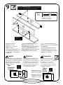
- Insert six METAL PINS (X)
into the short edges of the
UPRIGHT (C) and SMALL
BACK (J).
- Push the CAM DOWEL and
PINS (X) of the SMALL BACK (J)
and UPRIGHT (C) into the holes of
the RIGHT END (A).
NOTE
: Do not tighten the
HIDDEN CAM in the SMALL
BACK at this time.
- Fasten the BOTTOM (F) to the
RIGHT END (A). Tighten two
HIDDEN CAMS.
- Inserte seis ESPIGAS DE METAL (X)
dentro de los bordes cortos del
PARAL (C) y del DORSO
PEQUEÑO (J).
- Empuje el PASADOR DE
EXCÉNTRICO y las ESPIGAS (X) del
DORSO PEQUEÑO (J) y del PARAL (C)
en los agujeros del EXTREMO
DERECHO (A).
NOTA
: No apriete el EXCÉNTRICO
ESCONDIDO en el DORSO PEQUEÑO
en este momento.
- Fije el FONDO (F) al EXTREMO
DERECHO (A). Apriete dos
EXCÉNTRICOS ESCONDIDOS.
- Insérer six GOUPILLES EN
MÉTAL (X) dans les chants courts du
MONTANT (C) et PETIT ARRIÈRE (J).
- Enfoncer la CHEVILLE
D’EXCENTRIQUE et les
GOUPILLES (X) du PETIT ARRIÈRE (J)
et du MONTANT (C) dans les trous de
l’EXTRÉMITÉ DROITE (A).
REMARQUE
: Ne pas serrer
l’EXCENTRIQUE ESCAMOTABLE
dans le PETIT ARRIÈRE à ce point.
- Fixer le DESSOUS (F) à
l’EXTRÉMITÉ DROITE (A). Serrer deux
EXCENTRIQUES ESCAMOTABLES.
X
X
Do not stand the unit upright without the
BACK fastened. The unit may collapse.
No coloque la unidad en posición
vertical hasta que se fije el DORSO.
La unidad podría caerse.
Ne pas relever l’élément dans sa position
verticale avant d’avoir fixé l’ARRIÈRE.
L’élément risque de s’effondrer.
Caution
Attention
Precaución
F
A
Minimum 190 degrees
Minimum 190 degrés
Minimo 190 grados
Arrow
Flèche
Flecha
Maximum 210 degrees
Maximum 210 degrés
Mazximo 210 grados
409064

11
www.sauder. com/services
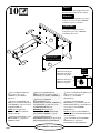
C
J
F
- Fasten the LEFT END (B) to
the BOTTOM (F). Tighten two
HIDDEN CAMS.
NOTE
: Be sure the METAL PINS
in the UPRIGHT (C) and SMALL
BACK (J) inserts into the holes in
the LEFT END. Do not tighten the
HIDDEN CAM in the SMALL
BACK at this time.
- Fije el EXTREMO IZQUIERDO (B)
al FONDO (F). Apriete dos
EXCÉNTRICOS ESCONDIDOS.
NOTA
: Asegúrese de insertar las
ESPIGAS DE METAL sujetadas al
PARAL (C) y al DORSO PEQUEÑO (J)
dentro de los agujeros del EXTREMO
IZQUIERDO. No apriete el
EXCÉNTRICO ESCONDIDO en el
DORSO PEQUEÑO en este momento.
- Fixer l’EXTRÉMITÉ GAUCHE (B)
au DESSOUS (F). Serrer deux
EXCENTRIQUES ESCAMOTABLES.
REMARQUE
: S’assurer de bien insérer
les GOUPILLES EN MÉTAL situées sur
le MONTANT (C) et PETIT
ARRIÈRE (J) dans les trous dans
l’EXTRÉMITÉ GAUCHE. Ne pas serrer
l’EXCENTRIQUE ESCAMOTABLE
dans le PETIT ARRIÈRE à ce point.
B
Minimum 190 degrees
Minimum 190 degrés
Minimo 190 grados
Arrow
Flèche
Flecha
Maximum 210 degrees
Maximum 210 degrés
Mazximo 210 grados
409064

12
www.sauder. com/services
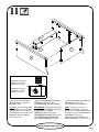
Unfinished surface
Surface non finie
Superficie sin acabado
Rounded edge
Chant arrondi
Borde redondeado
- Fasten the TOP (D) to the
ENDS (A and B). Tighten four
HIDDEN CAMS.
- Fije el PANEL SUPERIOR (D) a los
EXTREMOS (A y B). Apriete cuatro
EXCÉNTRICOS ESCONDIDOS.
- Fixer le DESSUS (D) aux
EXTRÉMITÉS (A et B). Serrer quatre
EXCENTRIQUES ESCAMOTABLES.
D
A
B
Minimum 190 degrees
Minimum 190 degrés
Minimo 190 grados
Arrow
Flèche
Flecha
Maximum 210 degrees
Maximum 210 degrés
Mazximo 210 grados
409064

13
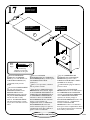
www.sauder. com/services
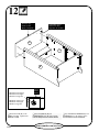
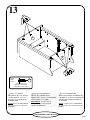
- Fixer sept CONSOLES EN
MÉTAL (W) au DESSUS (D) et
DESSOUS (F). Utiliser sept VIS NOIRES
TÊTE LARGE 14 mm (MM).
REMARQUE : S’assurer que les
CONSOLES sont à fleur du chant
supérieur du DESSOUS.
- Fasten seven METAL
BRACKETS (W) to the TOP (D)
and BOTTOM (F). Use seven
BLACK 9/16” LARGE HEAD
SCREWS (MM).
NOTE
: Be sure the BRACKETS
are even with the top edge of the
BOTTOM.
- Fije siete SOPORTES DE
METAL (W) al PANEL SUPERIOR (D) y
al FONDO (F). Utilice siete TORNILLOS
NEGROS DE CABEZA GRANDE de
14 mm (MM).
NOTA: Asegúrese que los SOPORTES
estén nivelados con el borde superior del
FONDO.
W
W
D
F
7usedinthisstep
7 utilisées à cette étape
7 utilizados en este paso
Black
Noire
Negro
MM
409064

14
409064
www.sauder. com/services
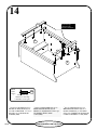
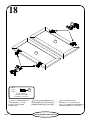
- Fixer les MOULURES (N) sur les
CONSOLES EN MÉTAL (W) du
DESSUS et du DESSOUS. Utiliser sept
VIS NOIRES TÊTE LARGE
14 mm (MM).
- Fasten the MOLDINGS (N) to
the METAL BRACKETS (W) on
the TOP and BOTTOM. Use seven
BLACK 9/16” LARGE HEAD
SCREWS (MM).
- Fije las MOLDURAS (N) a los
SOPORTES DE METAL (W) en el
PANEL SUPERIOR y en el FONDO.
Utilice siete TORNILLOS NEGROS DE
CABEZA GRANDE de 14 mm (MM).
D
F
7usedinthisstep
7 utilisées à cette étape
7 utilizados en este paso
Black
Noire
Negro
MM
N
Rounded edge
Chant arrondi
Borde redondeado
N

15
409064
www.sauder. com/services
8usedinthisstep
8 utilisées à cette étape
8 utilizados en este paso
Black
Noire
Negro
MM
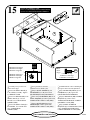
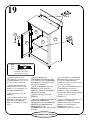
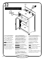
- Carefully turn your unit over
onto its front edges.
- Fasten the SMALL BACK (J)
to the ENDS (A and B). Tighten
two HIDDEN CAMS.
- Fasten two HINGES (BB) to the
SMALL BACK (J). Use four
BLACK 9/16” LARGE HEAD
SCREWS (MM).
- Fasten the SMALL TOP (E) to
the HINGES. Use four BLACK
9/16” LARGE HEAD
SCREWS (MM).
- Cuidadosamente voltee la unidad para
que repose sobre los bordes delanteros.
- Fije el DORSO PEQUEÑO (J) a los
EXTREMOS (A y B). Apriete dos
EXCÉNTRICOS ESCONDIDOS.
- Fije dos BISAGRAS (BB) al DORSO
PEQUEÑO (J). Utilice cuatro
TORNILLOS NEGROS DE CABEZA
GRANDE de 14 mm (MM).
- Fije el PANEL SUPERIOR
PEQUEÑO (E) a las BISAGRAS. Utilice
cuatro TORNILLOS NEGROS DE
CABEZA GRANDE de 14 mm (MM).
- Avec précaution, retourner
l’élément sur ses chants avant.
- Fixer le PETIT ARRIÈRE (J) aux
EXTRÉMITÉS (A et B). Serrer deux
EXCENTRIQUES ESCAMOTABLES.
- Fixer deux CHARNIÈRES (BB) sur le
PETIT ARRIÈRE (J). Utiliser quatre VIS
NOIRES TÊTE LARGE 14 mm (MM).
- Fixer le PETIT DESSUS (E) aux
CHARNIÈRES. Utiliser quatre VIS
NOIRES TÊTE LARGE 14 mm (MM).
B
A
E
BB
J
Tighten these HIDDEN CAMS.
Serrer ces EXCENTRIQUES ESCAMOTABLES.
Apriete estos EXCÉNTRICOS ESCONDIDOS.
Minimum 190 degrees
Minimum 190 degrés
Minimo 190 grados
Arrow
Flèche
Flecha
Maximum 210 degrees
Maximum 210 degrés
Mazximo 210 grados

16
409064
www.sauder. com/services
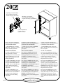
Do not stand the unit upright without the
BACK fastened. The unit may collapse.
No coloque la unidad en posición
vertical hasta que se fije el DORSO.
La unidad podría caerse.
Ne pas relever l’élément dans sa position
verticale avant d’avoir fixé l’ARRIÈRE.
L’élément risque de s’effondrer.
Caution
Attention
Precaución
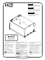
- Unfold the BACK (K) and lay it
over your unit.
- Make equal margins along the
bottom and side edges of the
BACK (K). Push on opposite
corners of your unit if needed to
make it “square”.
- Fasten the BACK (K) to your
unit using the NAILS (PP).
NOTE
: Perforations have been
provided for access through the
BACK. Carefully cut out the holes
needed.
- Desdoble el DORSO (K) y colóquelo
sobre la unidad.
- Los márgenes a lo largo de los bordes
laterales e inferior del DORSO (K) debe
estar uniforme. Empuje sobre las
esquinas opuestas de la unidad si es
requerido para hacerla “cuadrada.”
- Fije el DORSO (K) a la unidad
utilizando los CLAVOS (PP).
NOTA
: Hay perforaciones provistas para
el acceso a través del DORSO.
Cuidadosamente corte los agujeros
requeridos.
- Déplier l’ARRIÈRE (K) et le placer
sur l’élément.
- Veiller à avoir des marges égales le
long du chant inférieur et des chants
latéraux de l’ARRIÈRE (K). Si besoin
est, enfoncer sur les coins opposés de
l’élément pour s’assurer d’être «
d’équerre ».
- Fixer l’ARRIÈRE (K) à l’élément en
utilisant les CLOUS (PP).
REMARQUE
: Des lignes perforées ont
été prévues pour accéder facilement à
l’ARRIÈRE. Découper avec précaution
les trous nécessaires.
K
26 used in this step
26 utilisés à cette étape
26 utilizados en este paso
PP
La page charge ...
La page charge ...
La page charge ...
La page charge ...
La page charge ...
La page charge ...
La page charge ...
La page charge ...
-
 1
1
-
 2
2
-
 3
3
-
 4
4
-
 5
5
-
 6
6
-
 7
7
-
 8
8
-
 9
9
-
 10
10
-
 11
11
-
 12
12
-
 13
13
-
 14
14
-
 15
15
-
 16
16
-
 17
17
-
 18
18
-
 19
19
-
 20
20
-
 21
21
-
 22
22
-
 23
23
-
 24
24
-
 25
25
-
 26
26
-
 27
27
-
 28
28


Sauder 409064 Assembly Instructions Manual
- Taper
- Assembly Instructions Manual
dans d''autres langues
- English: Sauder 409064
- español: Sauder 409064
Documents connexes
-
Sauder 409086 Assembly Instructions Manual
-
-
-
-
-
-
-
-
-