KitchenAid KWCU360JSS0 Le manuel du propriétaire
- Catégorie
- Hottes
- Taper
- Le manuel du propriétaire
Ce manuel convient également à

IMPORTANT:
Read and save
these instructions.
IMPORTANT:
Installer: Leave Installation Instructionswith
the homeowner,
Homeowner: Keep Installation Instructionsfor
future reference,
Save Installation Instructionsfor local electrical
inspector's use.
Part No. 43294091/8284829 Rev.B
o
Piece N 43294091/8284829 R_v. B
Quick Reference
Table of Contents:
Pages
] Before you start
[] Product dimensions
[] Cabinet dimensions
[] Venting requirements
[] Electrical requirements
[]- [] Installation steps
[] Use and Care Information
[] Wiring diagrams
[] Accessories
] Warranty
[_-[] Requesting Assistance
or Service

Your safety and the safety of
others is very important.
We haveprovided many irnportant
safety messagesin this manualand
on your appliance,Always readand
obey all safety messages.
!_ his is the safety alert symbol
This symbol alerts you to
potential hazardsthat cankill
or hurt you and others. All safety
messageswill follow the safety alert
symbol and eitherthe word "DANGER"
or "WARNING".Thesewords mean:
Youcanbe killed or seriouslyinjured
if you don't immediatel_Lfollow
instructions.
Youcanbe killed or seriouslyinjured
if you don'tfollow instructions.
All safety messageswill tell you what
the potential hazardis, tell you howto
reducethe chanceof injury, and tell
you what can happen if the
instructions are not followed.
Important: Observe all governing
codes and ordinances.
Proper installation is ",/ourresponsibility:
• Have a qualified technician install this
range hood.
• Comply with installation clearances
specified on the model/serial rating
plate.
The model/serial rating plate is located
inside the range hood on the rear wall.
Rangehood location should be away from
strong draft areas,such aswindows, doors
and strong heating vents.
Cabinet opening dimensions that are
shown must be used. Given dimensions
provide minimum clearance. Consult
your cooktop/range manufacturer
installation instructions before making
any cutouts.
Grounded electrical outlet is required.
See "Electrical requirements:'
The canopy hood is factory set for
venting through the roof or wag.To vent
directly through the wall, the blower
must be rotated to face the rear of the
range hood.
All openings in ceiling and wall where
range hood will be installed must be
sealed.
WARNING -- TO REDUCE THE
RISK OF FIRE, ELECTRIC
SHOCK, OR INJURY TO
PERSONS, OBSERVE THE
FOLLOWING:
Installation work and electrical
wiring must be done by qualified
person(s) in accordance with aii
applicable Codes and Standards,
including fire related construction.
Sufficient air is needed for proper
combustion and exhausting of
gases through the flue (chimney)
of fuel burning equipment to
prevent back drafting. Follow the
heating equipment
manufacturer's guideline and
safety standards such as those
published by the National Fire
Protection Association
(NFPA),and the American Society
of Heating Refrigeration and Air
Conditioning Engineers
(ASHRAE), and the local code
authorities.
When cutting or drilling into wall
or ceiling, do not damage
electrical wiring and other hidden
utilities.
Ducted fans must always be
vented to the outdoors.
WARNING --To reduce the risk
of fire, use only metal ductwork.
This unit must be grounded.
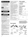
Toolsneeded:
,1,,dr,,,bit
penci, p,lers '
/ V
measuring _'_:_)
tape or ruler
wire stripper
or utility knife
Partsneeded:
2 U.L.- or C.S.A.- listed, 1/2" (12.5 mm)
conduit connectors
power supply cable
1wall or roof cap
metal vent system
Partssupplied:
Mountingscrews
36" (91.4cm) = 2
42"(106.7cm)= 4
48"(121.9cm) =4
Exhaustoutletcover _"
36" (91.4cm) = 1 _"
42" (106.7cm)= 1
48" (121.9cm) =2
Oamperscrews: I
36" (91.4cm) = 2
42"(106.7cm)= 2
48"(121.9cm) =4
Damper: _*
36"(91.4cm)=1
42" (106.7cm) =
48"(121.9cm) =2
Note: Backsplash,vent cover,discharge
transition, and chimney extension kits are
available from your dealer (see page 9).These
are required for some installations and must
be installed at time of hood installation as
shown in the Installation Instructions.
caulking gun and
weatherproof
caulking
compound
saber or
keyhole saw
duct ta
screwdriver
screwdriver
2

12 t_
(30,5 cm)
(if used)
18-3/16"
(46.2 cm)
2-7/32"
(5,5 cm)
25-3
(64 cm)
_ 1-3/8"
(3.5 cm)
36" 191.4 cm) hood: 35-7/8" 191,1 cm)
1106.7 cm) hood: 41-7/8" 1106,4 crn)
46" 1121,9 cm) hood: 47-7/8" 1121.6 cm)
Vent system must terminate to the outside.
Do not terminate the vent system in an attic or other
enclosed area.
Do not use 4-inch (10.2cm) laundry-type wall caps.
Use metal vent only.Rigid metal vent is recommended. Do
not use plastic or metal foil vent.
Forthe most efficient and
quiet operation:
• The size of the vent should be uniform.
• Use no more than three 90+elbows.
• Make sure there is a minimum of 24" (61 cm) of straight
vent between the elbows if more than one elbow is used.
• Do Not install two elbows together.
• The length of vent system and number of elbows should
be kept to a minimum to provide efficient performance.
• The vent system must have a damper. If roof or wall cap
has a damper, Do Not use damper supplied with the
range hood.
• Use duct tape to seal all joints in the vent system.
• Use caulking to seal exterior wall or roof opening around
the cap.
Determine which venting method is best for your
application and follow "Preparation" under "Installation
steps" on Page 5.
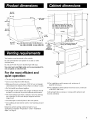
18" (45.7 cm)
min.
clearance
upper
cabinet to
countertop
36" (91.4 cm) hood: 36" (91.4 cm)
42" (106.7 cm) hood: 42" 1106.7 cm)
48" 1121.9 cm) hood: 48" 1121.9 cm)
rain. cabinet opening widths
canopy
cabinet depth __
30" (76.2 crn) rain. bottom of
py to cooking surface
36" (91.4 cm)
base cabinet
height
@ For installations with canopy only, minimum of
84-3/16" (213.8 cm).
® For installations with optional vent hood cover, minimum
of 96-3/16" (244.3 cm).
Ceiling height above canopy or canopy with optional vent
hood is unlimited.
3

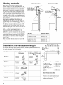
Venting methods
This canopy range hood is factory set for
vertical venting. For rear vent applications, the
blower must be turned inside the range hood so
that the blower vents to the rear as indicated.
The blower is turned by removing two screws
on each side of the blower, rotating the blower
with the exhaust opening facing the rear and
then replacing the screws.The exhaust cover(s)
must be moved to block the unused opening(s).
The blower must be converted before installing
the range hood.
Vent system needed for installation is not
included.The 36" (91.4cm) and 42" (106.7 cm)
models have one exhaust opening. 3-1/4" x 10"
(8.3 cm x 25 cm) rectangular, 7" (17.8cm) round,
8" (20.3 cm) round, 9" (22.9 cm) round, or 10"
(25.4 cm) round vent may be used.The hood
exhaust opening is 3-1/4" x 10"(8.3 cm x 25 cm).
The 48" (121.9cm) model has two 3-1/4" x 10"
(8.3 cm x 25 cm) exhaust openings. It is
recommended thatVentTransition Kit No.
8284757 be used to transition the two openings
into one 10" (25.4 cm) round vent. (Cannot be
used with Chimney Extension Kit No. 8284754.)
Vent system can terminate either through the
roof or wall.
The vent system length should not exceed the
lengths shown in the chart.
Vertical venting
roof cap
3-1/4" x 10"
(8.3 cmx 25 cm
vertical ventin
(roof or wall)
Horizontal venting
3-1/4" x 10"
(8.3 cmx 25 crr
horizontal venting
wall cap
Vent size Maximum length
3-1/4" x 10"(8.3cm x 25 cm) 35 ft. (10.7m)
7" (17.8cm) round 40 ft. (12.2m)
8" (20.3cm) round 50 ft. (15.2m)
9" (22.9cm) round 60 ft. (18.3m)
10"(25.4cm) round 60 ft. (18.3m)
Calculating the vent system length
To calculate the length of the system you need, add the equivalent feet (meters)
for each vent piece used in the system.
Vent Piece 3-1/4" x 10"(8.3 cm x 25 cm 7" (178 cm), 8" (20.3 cm),
Rectangular 9" (22.9 cm), 10" (25.4 cm)
Round
45° elbow
90° elbow
"/0 feet
(2.1 m)
5.0 feet
(1.8m)
90° flat elbow 12.0feet
(3.7 m)
transition to round 5.0 feet
(1.5m)
wall cap 0.0 feet
(0.0 m)
4
2.5 feet
(0.8 m)
5.0 feet
(1.5 m)
Example for 3-1/4" x 10"
(8.3 cm x 25 cm) vent system
3-1/4" x 10" wall
(8.3 cm x 25 cm) cap
elbow
2"
102!m,__
Maximum length
1 -- 90° elbow
8 ft. (2.4 m) straight
1 -- wall cap
Length of 3-I/4" x 10"
(8.3cm x 25 cm)
system
= 35 ft. (10.7 m)
= 5ft. (1.5m)
= 8ft. (2.4m)
= Oft. (Om)
=13ft. (4m)
Note: Flexiblevent is Not
recommended.
Flexible vent creates back pressure
and air turbulence that greatly
reduces performance.

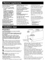
Important: Observe all governing
codes and ordinances.
It isthe customer's responsibility:
• To contact a qualified electrical
installer.
• To assure that the electrical
installation is adequate and in
conformance with National
Electrical Code, ANSI/NFPA 70
-- latest edition*, or CSA
Standards C22.1-94, Canadian
Electrical Code, Part 1 and
C22.2 No.0-NI91 - latest
edition** and all local codes
and ordinances.
If codes permit and a separate
ground wire is used, it is
recommended that a qualified
electrician determine that the
ground path is adequate.
A 120-volt, 60-Hz, AC-only, fused
electrical system is required on a
separate 15-amp circuit, fused on
both sides of the line.
Do not ground to a gas pipe.
Check with a qualified electrician if
you are not sure range hood is
properly grounded.
Do not have a fuse in the neutral or
ground circuit.
IMPORTANT.'
Save Installation Instructions for
electrical inspector's use.
The range hood must be connected
with copper wire only.
The range hood should be
connected directly to the fused
disconnect (or circuit breaker) box
through flexible armored or
nonmetallic sheathed copper cable.
A U.L.- or C.S.A.-listed strain relief
must be provided at each end of the
power supply cable. Wire sizes
(COPPERWIRE ONLY) and
connections must conform with the
rating of the appliance as specified
on the model/serial rating plate.
Wire sizes must conform to the
requirements of the National
Electrical Code ANSI/NFPA 70 --
latest edition*, or CSA Standards
C22.1-94, Canadian Electrical Code
Part 1 and C22.2 No. g-M91 - latest
edition** and all local codes and
ordinances.
A U.L.- or C.S.A.-listed conduit
connector must be provided at each
end of the power supply cable (at the
range hood and at the junction box).
Copies of the standards listed may be
obtained from:
National Fire Protection Association
One Satterymarch Park
Ouincy, Massachusetts 02269
_* CSA international
8501 East Pleasant Valley Road
Cleveland, Ohio 44131-5575
Preparation
It is recommended that the vent system be installed
before hood is installed.
Do not cut a joist or stud unlessabsolutely necessary.If a
joist or stud must be cut, then a supporting frame must
be constructed.
Before making cutouts, make sure there is proper
clearancewithin the ceiling or wall for exhaust vent.
Check that allthe installation parts and the box with
filters have been removed from the shipping carton.
= If possible, disconnect and move freestanding or
slide-in range from cabinet opening to provide easier
access to rear wall. Otherwise put a thick, protective
covering over countertop, cooktop or range to protect
from damage or dirt. Select a flat surface for assembling
the unit. Cover that surface with a protective covering and
place all hood parts and hardware in it.
= Determine and mark the centerline on the wall
where the hood will be installed. If the vent system is
already installed, use centerline of vent opening.
= If venting horizontally out the back of hood and vent
system is not installed, mark and cut vent opening now.
= Important: If used, Backsplash Kit must be
installed before installing the hood.
If a backsplash is not used, go to Step 5.
Backsplash installation: (The hardware package
supplied with the kit includes 4 plastic wall anchors
and mounting screws.)
•The height of the backsplash will determine the height
topofbacksplash
corner
mounting
hole (4)
36I' (91.4 cm) _-I
42 {106.7cm} F " I
Extends from
19-23/32" (50.1 cm}
to 39" 199.1cm)
of the hood. Note: The minimum height of the hood
above the cool<top, as shown on Page 3, is 30"
(76.2 cm). The backsplash can be extended from
19-23/32" (50.1 cm) to 39" (99.1 cm). Note: As the 30"
(76.2 cm) installation height increases, the hood's
capture area decreases.
• Determine the height of the hood.
• Position the hood on the wall so that the top of the
backsplash is at the height of the bottom edge of
hood. Mark the location of the four corner holes. It is
recommended that the backsplash be attached to the
wall at all four corners. However, the lower flange
can be secured between the wall and backsplash,
countertop or cabinet base without using the bottom
corner screws.
• Drill 5/16" (8 ram) holes.
• Push the plastic wall anchors all the way into the holes.
• Position the holes in the backsplash over the wall
anchors and attach using the screws supplied. 5

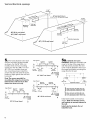
Vent and Electrical openings
/6"
(29 cm)
Electrical
opening
36" (91.4 cm) hood
42" (106,7 cm) hood
1-1/4"
(3,2 cm)
All vent openings are
3-1/4" x 10" (8.3 cm x 25.4 crn)
48" (t21,9 cm) hood
6-3/32"
_(15.5 cm)
6-3/32
(15.5 crn)
I
T Electrical opening
10-1/2"
(26,7 cm)
2-7/8"
(7.5 crn)
= The hood attaches to the wall
with the mounting screws located
as shown. For the 36" (91.4 cm)
models, there are two mounting
screws. For the 42" (106.7 cm) and
48" (121.9 cm) models, there are
four mounting screws. Install the
screws into the wall until the screw
heads are tight against the wall and
horizontal.
Note:The screws provided for
mounting this range hood must be
fastened into solid wood. Do Not
fasten into sheet rock only.
top of hood
±
1-1/16"
(17.5 cm)
15-9/16" 15-9/16"
(393 cm) i (393 cm) i
48" (121.9 crn)
rnin. to cooking
surface
36" (91.4cm) hood J_
T
top of hood
\ i 18-9/16" 16-9/16"
±
i {472cm) _ 147.2cm) i
1-1/16" 4-1/4" 4-1/4"
(175 cm) {10,8 cm) 110,8 cm)
42" (196.7 cm) hood
48" (121,9 crn)
rnin, to cooking
surface
top of hood
\ , 12514,_/lc_, , (214.'/lc_ ) ,
1-1116" T' 7"
(17,5 cm) 1178 cm) (178 cm}
48" (121.9 crn)
rnin. to cooking
surface
48" (121.9cm) hood
T
a. Optional vent cover
installation:Attach the full-width vent
cover to the top of the range hood
with the screws provided.The vent
cover must be attached to the top of
the range hood before mounting the
range hood to the wall.
Mounting brackets j
I I
I I
A
36" (91.4 cm) hood: 16-15/32" (41.8 cm)
42" (106.7 cm) hood: 19-15/32" (49.4 cm)
48" (121.9 cm) hood: 22-15/32" (57.1 cm)
B
36" (91.4 cm) hood: 32-15/16" (83.7 crn)
42" (106.7 cm) hood: 38-15/16" (98.9 cm)
48" (121.9 cm) hood: 44-15/16" (114.1 cm)
Install each bracket on the wall as
shown. Make sure that the screws
and brackets are securely fastened to
the wall.
Install only the brackets. Do net
install the hood.
6

If chimney extension is
used:Attach the extension brackets
as shown.
10-518" ceiling
(27 cm) //_//,/////
8-1/8" 8-1/8"
(20.6 cm_ (20.6 cm)
23" (58,4crn) max,
12" (30.5 cm) rain,
top of hood
......
Make sure that the screws are
securely fastened to the wall.
Excessive Weight Hazard
Use two or more people to move
and install range hood.
Failure to do so can result in
back or other injury.
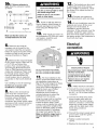
= If roof or wall cap does not
have a damper, attach damper to
exhaust opening(s) on top of the
hood using two Phillips-head
screws.
0= If 48" (121.9 cm) hood is to
be connected to 10" (25.4 cm) round
vent system, install the vent
transition piece now.
2. The brackets are also used
to adjust the level of the canopy.
Using a Phillips screwdriver, rotate
the screw V2 to adjust the level of
the canopy.
3 • Connect vent system to
hood. Seal all joints with duct tape.
4. If your installation uses the
optional vent cover, fit the cover
flanges over the brackets. If
installation uses the chimney
extension, fit the extension over the
brackets. Install the upper section
first, then fit the lower section over
the upper section. Seal extension to
hood with duct tape.
• Determine and make all
necessary cuts in the wall for the
vent system. Install the vent system
before the canopy hood. See venting
methods on Page 4, and hood vent
opening dimensions on Page 6.
• Determine the required height
for the power supply cable and cut
a 1-1/4" (3.2 cm) hole at this
location. Run wire through hole
according the National Electrical
Code or CSA Standards and local
codes and ordinances.There must
be enough power supply cable
from the fused disconnect (or
circuit breaker) box to make the
connection in the hood's electrical
box.
Use caulking to seal all openings.
Do Not turn on power until
installation is completed,
• Remove the terminal box
cover from the canopy hood.
Remove the power supply cable
knockout using a flat-blade
screwdriver. Attach conduit
connector into power supply cable
opening so that conduit connector
clamping screws are inside of
canopy hood.
bracket
wall
hood mounting
screw
36" (91.4 cm) hood has two brackets
42" (106.7 cm) hood has four brackets
48" (121.9 cm) hood has four brackets
1.The hood attaches to the
wall by screws discussed earlier in
the installation instructions at
Step 5.The hood hangs from these
screws by brackets inside the
range hood. Before attempting to
hang the hood, use a Phillips
screwdriver to rotate the
adjustment screw marked V1
counterclockwise to extend the
brackets from the canopy.
Hang the range hood by inserting
the brackets into the mounting
screws as shown. Note: These
screws must be installed into solid
wood to support the weight of the
hood as described in Step 5. Rotate
the screws marked Vl to tighten
the range hood against the wall.
Make sure that the range hood is
securely tightened against the
wall.
Electrical
connection
Electrical Shock Hazard
Disconnect power before making
electrical connections,
Connect ground wire to green
ground screw in terminal box.
Failure to do so can result in
death or electrical shock.
5 • Make electrical connection:
[] Connect the power supply cable
to hood terminal box through
the U.L.- or C.S.A.-listed conduit
connector.
[]
Connect the white wire of the
power supply cable with the
white lead in the hood using a
twist-on connector; connect the
black wire of the power supply
cable with the black lead in the
hood using a twist-on
connector.
[]
[]
Connect the power supply green
ground wire under the green,
ground screw.
Tighten conduit connector
screws.
[] Replace the terminal box cover.
7

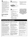
6= Installthefilters.
• Removethefiltersfromthebox
andremovethewhiteprotective
coatingfromthefilters.
• Grasponeofthefilterssothat
theknobfacesdownandtoward
thebackofthehood.
• Insertthefilterendwithoutthe
knobintotheretainingchannel
inthefront ofthe hood.
• Pullandturntheknobtotheleft
(counterclockwise)sothatthe
lockingleverdoesnotprotrude
fromthefilter.
• Inserttheknobendofthefilter
intotheretainingchannelinthe
backofthehood.
•Turn the knob to the right
(clockwise) to lock the filter in
place.
• Repeat for remaining filters.
Check operation
17. Tornpoweron.
8= The canopy hood
controls are located on the right-
hand underside of the canopy.
controls
-filters
9. Check the operation of
the range hood:
[]
[]
[]
[]
Move light switch to
"1" position. The light should
turn on.
Move blower switch to
"1" position. The blower
should operate.
Move the blower speed switch
to: "1" position for low speed,
"2" position for medium
speed, or "3" position for high
speed.
Move blower and light
switches to "0" position to
turn blower and light off.
If range hood does not operate:
[] Check that the circuit breaker
is not tripped or the house
fuse blown.
[] Disconnect power supply.
Check that wiring is correct.
To get the most efficient
use from your new range
hood, read the "Use and
Care Information" section.
Keep your KitchenAid
Installation Instructions and
Use and Care Guide close
to range hood for easy
reference.
8
WARNING --To reduce the risk of
fire or electrical shock, do not use
this fan with any solid-state speed
control device.
WARNING --TO REDUCETHE
RISK OF FIRE, ELECTRIC SHOCK,
OR INJURYTO PERSONS,
OBSERVETHE FOLLOWING:
Use this unit only in the manner
intended by the manufacturer. If
you have questions, contact the
manufacturer. Before servicing or
cleaning unit, switch power off at
service panel and lock the service
disconnecting means to prevent
power from being switched on
accidentally. When the service
disconnecting means cannot be
locked, securely fasten a
prominent warning device such as
a tag to the service panel
CAUTION: For general ventilating
use only. Do not use to exhaust
hazardous or explosive materials
and vapors.
WARNING --TO REDUCETHE
RISK OF A RANGETOP GREASE
FIRE:
Never leave surface units
unattended at high settings.
Boilovers cause smoking and
greasy spillovers that may ignite.
Heat oils slowly on low or
medium settings.
Always turn hood ON when
cooking at high heat or when
cooking flaming foods.
Clean ventilating fans frequently.
Grease should not be allowed to
accumulate on fan or filter.
Use proper pan size. Always use
cookware appropriate for the size
of the surface element.
WARNING --TO REDUCETHE
RISK OF INJURYTO PERSONS IN
THE EVENT OF A RANGETOP
GREASE FIRE, OBSERVETHE
FOLLOWING:
SMOTHER FLAMES with a close-
fitting lid, cookie sheet, or metal
tray, then turn off the burner. BE
CAREFULTO PREVENT BURNS. If
the flames do not go out
immediately, EVACUATE AND
CALLTHE FIRE DEPARTMENT
NEVER PICK UP A FLAMING PAN
--You may be burned.
DO NOT USE WATER, including
wet dishcloths or towels -- a
violent steam explosion will
result. Use an extinguisher ONLY
if:
You know you have a Class ABC
extinguisher, and you already
know how to operate it.
The fire is small and contained in
the area where it is started.
The fire department is being
called.
You can fight the fire with your
back to an exit.

Replacing the Halogen
lamps:
Before you begin, make sure that
the range hood is turned off and
that the other lamps have had
sufficient time to cool. Halogen
bulbs burn extremely hot.
To replace a halogen lamp:
• Remove 2 screws from the
circular metal trim around the
lamp assembly.
• Pull the trim with the lamp
assembly attached down far
enough so that the lamp can be
pushed out of the socket.
• Insert the new lamp into the
socket and push the lamp and
trim assembly back up into the
hood.
• Replace the trim.
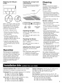
Operation
The canopy hood is designed to
remove smoke, cooking vapors
and odors from the cooktop area.
For best results, start the hood
before cooking and allow it to
operate several minutes after the
cooking is complete to clear all
smoke and odors from the
kitchen.
Opening the canopy hood
control panel:
The hood controls are located on
the right-hand underside of the
canopy.
controls
\
\
\
light blower blower speed
switch switch switch
Operating the light:
ON: Move the light switch to the
"1" position.
OFF: Move the light switch to the
"0" position.
Operating the blower:
ON: Move the blower switch to
the "1" position.
OFF: Move the blower switch to
the "0" position.
Adjusting the blower speed:
The blower has three speed
control.
Move the blower speed switch to:
"1" position for low speed,
"2" position for medium speed,
or "3" position for high speed.
Cleaning
Filters:
The filters should be washed
frequently. Place metal filters in
dishwasher or hot detergent
solution to clean.
To remove filters:
• Pull knob forward, toward the
front of the hood, while turning
the knob to the left (counter-
clockwise) to release the locking
lever.
To reinstall filters, see Step 16.
Exterior surfaces:
• Do not use steel wool or soap-
filled scouring pads.
• Rub in direction of the grain line
to avoid marring the surface.
•Always wipe dry to avoid water
marks.
• KitchenAid ® Professional
Formula Stainless Steel Cleaner
& Polish is the cleaner
recommended for cleaning
stainless steel surfaces on this
product.To order call our
Customer Service Center at
1-800-442-9991 or order on-line at
www.a pplia nceaccessories.com
and ask for part number
8171420.To order from Canada,
call 1-800-807-6777.
• If commercial cleaners are used,
follow label directions. Do not
use products that contain
chlorine (bleach). Chlorine is a
corrosive substance.
For routine cleaning and
fingerprints, use liquid detergent
soap and water, or all-purpose
cleaner. Wipe with damp cloth or
sponge, then rinse with clean
water and wipe dry.
Optional Installation Kits available from your dealer.
Note: Kits are available in stainless steel only.
Backsplash: Must be installed before hood is installed.
36" (91.4 cm) hood: Kit No. 8284756
42" (196.7 cm) hood: Kit No. 8284827
48" (121.9 cm) hood: Kit No. 8284755
Vent covers: 12" (30.5 cm) high, 12" 30.5 cm) deep.
36" (91.4 cm) hood: Kit No. 8284753
42" (196.7 cm) hood: Kit No. 8284828
48" (121.9 cm) hood: Kit No. 8284752
Chimney extensions: extends from 12" (30.5 cm) to
23" (58.4 cm) high. For use with 36" (91.4 cm),
42" (106.7 cm) and 48" (121.9 cm) hoods:
Kit No. 8284754
Vent transition: transitions from two 3-1/4" x 10"
(8.3 x 25.4 cm) vents to one 10" (25.4 cm) round vent.
Not for use with chimney extension Kit No. 8284754.
36" (91.4 cm) hood: Not available
42" (106.7 cm) hood: Not available
48" (121.9 cm) hood: Kit No. 8284757
9

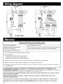
I }
0 1 0 _ 123
For 36" (91,4 cm) and
=o vAc 42" (106,7 cm) hoods
L_NI_ IN
Sw_cS"m_s
I I
ol ol 123
t=oVAC For 48" (121.9 cm) hoods
L_E_
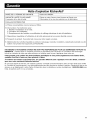
KitchenAid Range Hood Warranty
LENGTH OFWARRANTY KitchenAid WILL PAY FOR
LIMITED ONE-YEAR WARRANTY Labor and any parts of your range hood (except light bulbs and
From Date of Purchase filters) which are defective in materials or workmanship.
KitchenAid WILL NOT PAY FOR
A. Consumable parts such as light bulbs and filters.
B. Service calls to:
1. Correct the installation of the range hood.
2. Instruct you how to use the range hood.
3. Replace house fuses or correct house wiring.
C. Repairs when range hood is used in other than normal, single-family household use.
D. Pickup and delivery.This product is designed to be repaired in the home.
E. Damage to range hood caused by accident, misuse, fire, flood, act of God or use of products not approved
by KitchenAid.
KITCHENAID AND KITCHENAID CANADA DO NOT ASSUME ANY RESPONSIBILITY FOR INCIDENTAL OR
CONSEQUENTIAL DAMAGES. Some states or provinces do not allow the exclusion or limitation of incidental or
consequential damages, so this exclusion or limitation may not apply to you.
This warranty gives you specific legal rights, and you may also have other rights which may vary from state to
state or province to province,
Outside the United States and Canada, a different warranty may apply. For details, please contact your
authorized KitchenAid dealer.
If you need service, first see the "Check Operation" section of this book. After checking the "Check Operation;'
additional help can be found by checking the "Requesting Assistance or Service" section or by calling our
KitchenAid Customer Interaction Center, 1-800-235-0665 (toll-free), from anywhere in the U.S.A. or Canada.
10

To avoid unnecessary service calls, please
check the "Check Operation" section. It may
save you the cost of a service call. If you still
need help, follow the instructions below.
If you need assistance or service in U.S.A.
Call the KitchenAid Customer Interaction
Center toll-free at 1-800-235-0665,
Our consultants are available to assist you.
When calling: Please know the purchase date, and
L_ the complete model and serial number
of your appliance This information will
help us better respond to your request.
Our consultants provide assistance with:
• Features and specifications on our full line
of appliances
• Installation information
• Use and maintenance procedures
• Accessory and repair parts sales
• Specialized customer assistance (Spanish
speaking, hearing impaired, limited vision, etc.)
• Referrals to local dealers, service companies, and
repair parts distributors
KitchenAid designated service technicians are
trained to fulfill the product warranty and provide
after-warranty service, anywhere in the United
States.
To locate the designated KitchenAid service
company in your area, you can also look in your
telephone directoryYellow Pages.
If you need replacement parts
If you need to order replacement parts, we recom-
mend that you only use factory-authorized parts.
These parts will fit right and work right, because
they are made to the same exacting specifications
used to build every new KitchenAid* appliance.
To locate factory-authorized parts in your area, call
our Customer Interaction Center telephone number,
your nearest authorized service center, or KitchenAid
Factory Service at 1-800-442-1111.
For further assistance
If you need further assistance, you can write to
KitchenAid with any questions or concerns at:
KitchenAid Brand Home Appliances
Customer Interaction Center
c/o Correspondence Dept.
2000 North M-63
Benton Harbor, MI 49022-2692
Please include a daytime phone number in your
correspondence.
11

Before calling for assistance or service, please
check the "Check Operation" section. It may save
you the cost of a service call. If you still need
help, follow the instructions below,
If you need assistance or service in Canada
1.Ifthe problem isnot due to one of the items
listed in "Check Operation"f_.
Contact the dealer from whom you
purchased your appliance, or call the
KitchenAid Canada Customer
Interaction Center toll-free,
8:30 a.m. - 6 p.m. (EST),
at 1-800-235-0665.
2. If you need servicer...
Contact your nearest KitchenAid Canada Appli-
ance Service branch or authorized servicing
outlet to service your appliance. (See list below.)
Make sure the service company you contact is
authorized to service your appliance during the
warranty period.
tWhen asking for assistance or service, please
provide a detailed description of the problem,
your appliance's complete model and serial
numbers, and the purchase date.This
information will help us respond properly to
your request.
KitchenAidCanada Appliance Service- ConsumerServices
Direct service branches:
BRITISH COLUMBIA 1-800-665-6788
ALBERTA 1-800-661-6291
ONTARIO Ottawa area 1-800-267-3456
(except 807 area code) Outside the Ottawa area 1-800-807-6777
MANITOBA, SASKATCHEWAN 1-800-665-1683
and 807 area code in ONTARIO
QUEBEC MontreaI (except South Shore) 1-800-361-3032
South Shore Montreal 1-800-361-0950
Quebec City 1-800-463-1523
Sherbrooke 1-800-567-6966
ATLANTIC PROVINCES 1-800-565-1598
For further assistance
If you need further assistance, you can write to
KitchenAid Canada with any questions or concerns at:
Consumer Relations Department
KitchenAid Canada
1901 Minnesota Court
Mississauga, Ontario L5N 3A7
Please include a daytime phone number in your
correspondence.
Pa_ No. 43294091/8284829 Rev.B
Piece N° 43294091/8284829 Rev. B
@2001KitchenAid
@Registered trademarkff Mtrademark of KitchenAid, U.S.A., KitchenAid Canada licensee in Canada
6/2001
Printed in U.S.A.

IMPORTANT:
Lire et conserver
ces instructions.
IMPORTANT:
Installateur : Remettre les instructions
d'installation au propri_taire de I'appareil.
Proprietaire : Conserver les instructions
d'installation pour consultation ult_rieure.
Conserver les instructions d'installation
I'intention de I'inspecteur local des installations
_lectriques.
o
Piece N 43294091/8284829 R_v. B
Reference rapide
Table des matieres :
Pages
[] Avant de commencer...
[] Dimensions du produit
[] Dimensions des placards
[] Circuit de d_charge de Fair
[] Alimentation _lectrique
[]- [] Les _tapes de I'installation
] Utilisation et entretien
[] Schema de c_blage
[] Accessoires
[] Garantie
[_- [] Demande d'assistance ou
de service

Votre s_curit_ et celle des autres
est tr_s importante.
Nous donnons de nombreux
messages de secudt6 impertants dans
ce manuel, et sur votre appareil
menager. Assurez-veus de toujeurs life
tous Ies messages de s¢curit6 et de
vous y conformer.
_ oici le symbole d'alerte de
securit&
Ce symbole d'alerte de
securit6 vous signale les dangers
potentiels de deces et de bIessures
graves a vous eta d'autres.
Tousles messages de securit6
suivront le symbole d'alerte de
securit6 et le mot _<DANGER>>ou
<<AVERTISSEMENT>>.Ces roots
signifient :
Risque possible de d_c_s ou de
blessure grave si vous ne suivez
pas imm_diatement les instructions,
Risque possible de d_c_s ou de
blessure grave si vous ne suivez
pas les instructions.
Tousles messages de s6curite vous
diront queI est te danger potentiel et
vous disent comment reduire le risque
de blessure et ce qui peut se produire
en cas de non-respect des
instructions.
Important : Observer les
dispositions de tous les codes et
reglements en vigueur,
C'est &vous qu'incombe la
responsabilit_ de :
• Demander a un technicien qualifie
d'installer cette hotte.
• Respecter Iors de I'installation les
d_gagements de s_paration specifies
sur la plaque signal_tique de I'appareil.
La plaque signaletique (avec numero de
modele et numero de serie) est situ_e
I'int6rieur de la hotte, sur la paroi arri_re.
La hotte d'aspiration devrait toujours
8tre install6e &distance des sources de
courants d'air comme fenStres, portes et
bouches de chauffage.
On dolt respecterles dimensions
indiqu_es pour I'ouverture clans le
placard• Les dimensions indiqu_es
2
tiennent compte des d_gagements de
s_paration n_cessaires. Avant
d'effectuer un d_coupage, consulter
les instructions d'installation fournies
par le fabricant de la cuisini_re ou
table de cuisson.
Une prisede courant electrique reliee
la terre est n_cessaire. Voir
<_Specifications de I'installation
_lectrique >>.
La hotte d'aspiration est configur_e
I'usine pour la d_charge a travers le
toit ou un mur. Pour la d_charge
directe a travers un mur, on doit
changer I'orientation du ventilateur
pour le placer face a I'arri_re de la
hotte.
Assurer I'etancheite au niveau de
chaque ouverture decoupee dans le
plafond ou le tour pour I'installation
de la hotte.
AVERTISSEMENT - POUR
MINIMISER LES RISQUES
D'INCENDIE, CHOC ELECTRIQUEOU
DOMMAGES CORPORELS,
OBSERVERLES PRESCRIPTIONS
SUIVANTES :
Le travail d'installation et de c_blage
electrique doit _tre execute par des
)ersonnes comp_tentes et en con-
formit_ avec les prescriptions des
normes et codes applicables, ceci
incluant les normes de r_sistance au
feu des _l_ments de construction. La
disponibilit_ d'un volume d'air
appropri_ pour I'alimentation de
I'_quipement a combustion et I'e-
vacuation des gaz de combustion
)ar la chemin_e pour qu'il n'ait pas
de reflux est n_cessaire. Respecter
les directives du fabricant de
I'_quipement de chauffage et les
normes de securite, publiees par des
organismes comme la National Fire
Protection Association (NFPA),et la
American Society of Heating
Refrigeration and Air Conditioning
Engineers (ASHRAE), et par les
autorit_s r_glementaires locales.
Lors de toute operation de
d_coupage ou de perqage dans une
cloison ou un plafond, veiller a ne
_asendommager lea cables _lec-
triques et canalisations qui peuvent
s'y trouver.
Le conduit de decharge associ_ a un
ventilateur dolt se terminer _ I'ex-
terieur.
AVERTISSEMENT- Pour rSduire le
risque d'incendie, utiliser unique-
ment des conduits m6talliques.
Cet appareil dolt _tre relie a la terre.
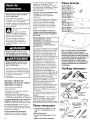
Pieces necessaires:
2 connecteurs de conduit 12,5 mm
(1/2 po) - homologation U.L. ou
CSA
c_ble d'alimentation
1 bouche de decharge pour toit ou
tour
conduit d'evacuation metallique
Piecesfournies :
Vis de montage:
91,4 cm (36 po) = 2
106,7cm (42 po) = 4 _._
121,9em (48 po) = 4 -_ <_'_
Plaquettes d'obturation _"_
(orifices de sortie) :
91,4 cm (36 po) = 1
106,7cm (42 po) = 1 _.
121,9em (48 po) = 2
Vis pour volet de _ ]
]
reglage : __ L___
91,4 cm (36 po) = 2 _
106,7cm (42 po) = 2 _
121,9cm (48 po) = 4 _"
Volet de reglage: o , o _
91,4 cm (36 po) = 1
106,7cm (42 po) = 1
121,9em (48 po) = 2
Note : D'autres pieces sont disponibles
chez le revendeur local (voir page 9) :
dosseret, garniture cache-conduit (pour le
sommet de la hotte), raccord de transition
et ensemble d'extension de cheminee. Ces
pieces peuvent 6tin necessaims dans
certaines installations, et elles doivent
alors *}tre utilisees Iors de I'installation de
la hotte conformement aux instructions
d'installation.
Outillage necessaire:
• _* perceuse
meche a bois
1 1/4 po
pistolet d'application
pour produits de
calfeutrage et
d'etancheite
scie sauteuse
ou scie
chantourner
, ruban adhesif
pour conduits pince/'j!
regle ou metre- _ _/
ruban _ _ pince a denuder/ _k__(
_*_,_*_•_'_-<'_*_'_ couteau utilitaire _
cisaille de
ferblantier e!_
tournevis -
lame plat tournews

30,5 cm
(12 po)
46,2 cm
(18 3/16 po)
30,6 cm
(12 1/32 po)
garniture _._
cache-conduit =_" I
(option) I
5,6 cm
(2 7/32 po}
(1 3t6 po)I
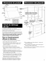
hotte 91,4 cm (36 po) : 91,4 cm (36 po)
hotte 106,7 cm (42 po) : 106,7 crn (42 po)
hotte 121,9 crn {48 po) : 121,9 cm (48
distance libre min, entre les placards
hotte
64 cm
(25 3/16 po)
hotte 91,4 cm (36 po) : I_r-_ I
cm (35 7/8 po) distance rnin, entre_ profondeur
hotte 106,7 cm (42 po) : le bas de la hotte et placard
106,4 cm (41 7/8 po) la table de cuisson po)
hauteur libre - po)
hotte 121,9 cm (48 po) : rain. au-dessus
121,6 cm (47 7/8 po) du plan de
travail
45,7 cm (18 po)
Le systeme dolt d_charger I'air a I'ext_rieur.
Ne pas terminer le conduit d'_vacuation au-dessus d'un
plafond ou dans autre espace fermi.
Ne pas utiliser une bouche de d_charge murale de 10,2cm
(4 po) normalement utilis_e pour un appareil de buanderie.
Utiliser uniquement du conduitmetallique. On recommande
I'emploi de conduit metallique rigide.Ne pasutiliserdes
conduitsde plastiqueou de metal mince/flexible.
Pourun fonctionnement
efficaceet silencieux :
• Lataille du conduit d'6vacuation dolt 6tre uniforme.
• Ne pas utiliser plus de trois coudes a 90+.
• S'il est n_cessaire d'installer plusieurs coudes, ceux-ci
devront _tre s_par_s par une section rectiligne d'au
moins 61 cm (24 po).
• Ne pas raccorder deux coudes ensemble.
• Pour maximiser I'efficacit_, minimiser la Iongueur
effective totale du systeme de d_charge et le nombre de
coudes.
• Le systeme de d_charge dolt comporter un volet de
reglage. Si la bouche de d_charge (sur le toit ou a travers
lemur) comporte un volet de r6glage, ne pas utiliser le
volet de r_glage fourni avec la hotte.
• Au niveau de chaque jointure du systeme de d_charge,
assurer I'_tanch_it6 avec du ruban adh_sif pour conduit.
• Autour de la bouche de d_charge a I'ext_rieur, assurer
I'etanch_it6 avec un produit de calfeutrage.
Determiner la m_thode d'evacuation de I'air la plus
appropri_e pour I'application, et ex_cuter la preparation
d_crite dans les instructions d'installation a la page 5.
hauteur des
placards
inferieurs
91,4 cm
(36 po)
@ Pour installation avec hotte seulement - minimum de
213,8 cm (84 3/16 po).
® Pour installation avec garniture cache-conduit (option) -
minimum de 244,3 cm (96 3/16 po).
Pasde limitation pour la hauteur du plafond au-dessus de la
hotte ou de la hotte avec garniture.
3

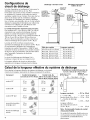
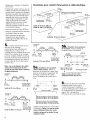
Configurations de
circuit de decharge
La hotte d'aspiration est configuree a I'usine pour la
d6charge a travers le toit ou un mur. Pour
I'_vacuation par I'arri_re, il faut modifier I'orientation
du ventilateur a I'int_rieur de la hotte pour que le
ventilateur rejette I'air par I'arri_re. Pour cela, 6ter les
deux vis de chaque c6t_ du ventilateur, changer
I'orientation du ventilateur pour placer la d_charge
face _ I'arri_re, puis reinstaller les vis. On dolt ensuite
d6placer les plaquettes d'obturation pour obturer les
ouvertures non utilisees. On dolt effectuer cette
conversion avant d'installer ]a hotte.
Le conduit d'evacuation necessairen'est pasinclus.
Les modules de 91, 4 cm (36 po) et 106,7crn (42 po)
comportent une ouverture de d_charge. On peut
utiliser un conduit d'_vacuation rectangulaire de
8,3 x 25 cm (3 1/4x 10 po), ou un conduit circulaire de
17,8cm (7 po), 20,3 cm (8 po), 22,9 cm (9 po) ou
25,4 cm (10 po) de diametre. La hotte compor_e un
orifice de d_charge de 8,3 x 25 cm (3 1/4 x 10 po).
La hotte de 121,9cm (48 po) comporte deux
ouvertures de d_charge de 8,3 x 25 cm (3 1/4x 10po).
On recommande I'utilisation de I'ensemble de
transition de conduit d'_vacuation n° 8284757 pour
connecter les deux ouvertures a un conduit circulaire
de 25,4 cm (10 po) de diam_tre. (Ne peut _tre utilis_
avec I'ensemble d'extension de chemin_e
n° 8284754.)
Le circuit de d_charge peut d#charger I'air &
I'ext_rieur a travers lemur ou a travers le toit.
La Iongueur effective du circuit ne dolt pas _tre
sup_rieure a la Iongueur indiqu_e dans le tableau.
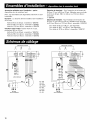
Decharge a travers le toit
conduit de
8,3 x 25 cm
(3 1/4 x 10 po)-
decharge
travers le toit
bouche de
/decharge
Decharge horizontale
travers le mur
conduit de
8,3 x25 cm _
(3 1/4 x 10 po)
decharge a
travers le tour
i bouche
de
decharge
murale
Tailledes conduits Longueur maximale
8,3 x 25 cm (3 1/4x 10po) 10,7 m (35 pi)
Road, dia. 17,8cm (7 po) 12,2 m (40 pi)
Rend, dia. 20,3 cm (8 po) 15,2 m (50 pi)
Rend, dia. 22,9 cm (9 po) 18,3 m (60 pi)
Rend, dia. 25,4 cm (10 po) 18,3 m (60 pi)
Calcul de la Iongueur effective du systeme de decharge
Pour calculer la Iongueur effective du syst_me de d6charge, on dolt tenir
compte de la Iongueur _quivalente de chaque composant du syst_me.
Composant Conduit rectangulaire Conduit rond, dia
8,3 x 25 cm (3 1/4 x 10 po) 17,8cm (7 po),20,3 cm (8 po)
22,9cm (9 po),25,4cm (10po
coude _ 45°
0,8 m
(2,5 pi)
2,1 m
(7 pi)
coude & 90° 1,5 m 1,5 m
(5 pi) (5 pi)
coude _ 90° plat 3,7 m
(12 pi)
raccord de transition 1,5 m
rectangle-fond (5 pi)
bouche de d_charge 0 m _
murale (0 pi)
4
Exemple pour conduit d'evacuation de
8,3 cm x 25 cm (3 1/4 po x 10 po)
Coude 8,3 x 25 cm bouchede
(3 1/4 x 10po) decharge murale
m
Longueur maximale
1-- coude a 90°
Section droite 2,4 m (8 pi) = 2,4 m
1-- bouche de d_charge
murale = 0 m
= 10,7m (35 pi)
= 1,5rn (5 pi)
(8 pi)
(0 pi)
Un conduit d'_vacuation flexible cr_e une
contre-pression et une turbulence de I'air
qui r_duisent consid_rablement la
performance.
Note : On deconseille I'emploi de conduit
d'evacuation flexible.
Longueur effective
de conduit de 8,8 x 25 cm
(3 1/4x10po) = 4m (13pi)

Important : Respecter les proscriptions
de tousles codes et reglements en
vigueur.
C'est au client qu'incombe la
msponsabilit_ de :
• Contacter un _lectricien qualifie pour
I'installation.
• Veillera ce que I'installation
electrique soit realiseed'une maniere
adequate et en confon_iteavec les
proscriptionsdu Codenationaldes
installationselectriquesANSI/NFPA
70 - derniereedition*, ou des normes
CSA C22.1.94/ Codecanadiende
I'electricit&1_repartie et C22.2 N°
0-M91 - derniereedition**, et avec
lesprescriptionsde tousles codeset
reglementsIocauxen vigueur.
Si un conducteurdistinct de liaisona la
terre est utiliseIorsquelecode le
permet,on mcommande qu'un
electricienqualifieverifieque la liaison
laterre est adequate,
L'appareil dolt _tre alimente par un
circuitde 120volts,60 Hz,CA
seulement,15 A, avecun fusible sur
chaqueconducteur.
Ne pas utiliser une tuyauterie de gaz
pour la liaison a la terre.
En cas d'incertitude quanta la qualit_
de la liaison a la terre de la hotte,
consulter un electricien qualifi&
Ne pasinstallerun fusibleen serieavec
leconducteurneutreou leconducteur
de liaisona la terre.
IMPORTANT :
Conserverlesinstructionsd'installation
I'intention de I'inspecteurlocaldes
installationselectriques.
La hotte dolt _tre raccordeeau reseau
electrique uniquement avec des
conducteurs de cuivre.
La hotte dolt _tre raccordee
directement au coupe-circuit avec
fusibles ou aux disjoncteurs par
I'intermediaire de c_ble
conducteurs de cuivre, a blindage
m_tallique flexible ou a gaine non
m_tallique. Un passe-ill
(homologation UL ou CSA) dolt _tre
install8 a chaque extr_mit_ du c_ble
d'alimentation. Lecalibre des
conducteurs (CUIVRE SEULEMENT) et
les pi_ces de connexion doivent 6tre
compatibles avec la demande de
courant de I'appareil sp_cifi_e sur la
plaque signal_tique.
La taille des conducteurs dolt satisfaire
les prescriptions du Code national des
installations _lectriques ANSI/NFPA 70
- derniere _dition*, ou des normes
CSA C22.1.94/ Code canadien de
I'_lectricit6, 18repartie et C22.2 N°
0-M91 - derni_re _dition**, et avec les
prescriptions de tous les codes et
r_glements Iocaux en vigueur.
Un connecteur de conduit
(homologation UL ou CSA) doit _tre
install_ a chaque extremite du c_ble
d'alimentation (sur la hotte et sur la
bofte de connexion).
On peut obtenir aux adresses suivantes des
exemplaires des normes mentionnees :
National Fire Protection Association
One Batterymarch Park
Quincy, Massachusetts 02269
*" CSA International
8501 East Pleasant Valley Road
Cleveland, Ohio 44131-5575
Preparation
II est preferable que le circuit d'_vacuation soit installe
avant I'installation de la hotte. On ne dolt couper une
solive ou un poteau de colombage que Iorsque cela est
absolument necessaire. S'il est necessaire de couper une
solive ou un poteau du colombage, on dolt construire une
structure de support appropriee.
Avant d'effectuer le decoupage, verifier que les distances
de separation appropriees seront respectees autour du
conduit d'evacuation, dans le plafond ou la cavite du mur.
Verifier que toutes les pieces necessairespour I'installation
et la boite comportant lesfiltres ont ete retirees de
I'emballage.
= Si c'est possible, debrancher la cuisini_re (autonome
ou mobile), et retirer la cuisini_re de son encastrement
entre les placards pour pouvoir acceder au mur arriere.
Sinon, placer un _pais mat_riau de protection sur le plan de
travail, la table de cuisson ou la cuisiniere, pour la
protection contre la poussiere et les dommages 6ventuels.
Choisir une surface plane pour I'assemblage de I'appareil.
Recouvrir cette surface d'un mat_riau de protection
appropri_ avant d'y placer tousles composants de la hotte
et les accessoires.
= Sur lemur, marquer la ligne qui correspondra a I'axe
central de la hotte apr_s son installation. Si le circuit
d'_vacuation est deja installS, utiliser I'axe central de
I'ouver_ure du conduit.
91,4 cm (36 po)
sornmet du dosseret \ 106,7 cm (42 po)
_. 121 9 cm 48po)
trous de I-- _/_
fixation darts _
les angles
Hauteur du dosseret :
50,1 crn (19 23/32 po)
",99,1 cm (39 po)
9,5 mm
25,4mm (1po)
= Pour une decharge par I'arri_re/horizontalement, si le
circuit d'_vacuation n'est pas installS, tracer et d_couper
maintenant I'ouverture de passage du conduit.
= Important : Si un dosseret dolt 6tre utilise (option), on
dolt I'installer avant la hotte.
Si aucun dosseret n'est utilis_, passer a I'_tape 5.
Installation du dosseret : (Cet ensemble comporte 4
chevilles de plastique pour I'ancrage mural, et 4 vis de
montage.)
• La hauteur du dosseret d_terminera la hauteur de la hotte.
Note : La hauteur minimale de la hotte au-dessus de la
table de cuisson est de 76,2 cm (30 po) (voir page 3). Le
dosseret peut _tre prolong_ de 50,1 cm (19 23/32 po)
99,1 cm (39 po). Note : L'augmentation de la hauteur de
76,2 cm (30 po) s'accompagne d'une diminution de
I'aire de capture de la hotte. 5

• D6terminer la hauteur d'installation
de la hotte.
• Positionner la hotte contre le mur en
faisant cofncider le bord inf@ieur de
la hotte avec le sommet du dosseret.
Marquer la position des quatre trous
des angles. On recommande que le
dosseret soit fix8 au mur clans les
quatre angles ;cependant on peut
aussi ne pas placer les vis des
angles inf_rieurs et caler la levre
inferieure entre le mur et un
dosseret existant, le plan de travail
ou le placard inf@ieur.
• Percer des trous de 8 mm (5/16 po).
• Enfoncer compl_tement les chevilles
de plastique dans les trous.
• Faire co'incider les trous du
dosseret avec les chevilles
d'ancrage et installer lea vis de
fixation fournies.
Ouvertures pour conduit d'evacuation et c ble electrique
3,2 cm
(1 1/4 po)
S,3 x 25,4 cm (3 1/4 x 10 po)
Ouverture pour 24,6 cm
c&ble electrique (S 11/16 po}
hotte de 9t,4 cm (36 po)
hotte de 106,7 cm (42 po)
hotte de 12t,9 cm (48 po)
EOuverture pour
c&ble electrique
26,7 cm
(10 1/2 po}
7,5 cm
(2 7/8 po)
= La hotte dolt 6tre fix6e au mur
avec les vis de montage
conformement aux indications de
I'illustration. II y a deux vis de
montage pour les modules de 91,4 cm
(36 po). II y a quatre vis de montage
pour les modeles de 106,7cm (42 po)
et 121,9 cm (48 po).Visser chaque via
horizontalement dans lemur jusqu'a
ce que la t6te de vis soit bien serr6e
contre le mur.
Note : Les visde fixation de la hotte
do/vent _tre visseesdans du bois
massif. Ne pas visser dans le panneau
de gypse seulement.
sornmet de
la hotte
±
÷
17,5 crn
(1-1/16 po)
39,S cm 39,5 cm
1(159/16 po) 1(15 9/16 po t
hotte de 91,4 cm (36 po)
121,9 cm (48 po}
au-dessus de la
table de cuisson
somrnet de
la hotte
47,2 cm 47,2 cm
(18-9/16
17,5 cm 10,S cm 1O,S cm
(1-1/16 po) (4-1/4 po) (4-1/4 po)
121,9 cm (49 po)
au-dessus de la
hotte de 106,7cm (42 po) tabledecuisson
sornmet de
la hotte
54,9 cm
±
t
17,5 cm 17,8 cm
(1-1/16 po) (7 po)
hotte de 121,9 cm (48 po}
54,9 cm
(21-9/16 po}
I
'17,8cm
(7 po)
121,9 cm (48 po)
au-dessus de la
table de cuisson
a. Installation de la garniture
cache-conduit (option) :Placer la
garniture au sornmet de la hotte; fixer
avec les vis fournies. La garniture dolt
_tre fix6e au sommet de la hotte
avant I'installation de la hotte sur le
mur,
/ "x t /
27,9 cm \\ _ / sommet
(11 po) "\ / de la hotte
brides de montage j
r ................. 1
I I
A
hotte 91,4 cm (36 po) :41,8 cm (16 15/32 po)
hotte 106,7 cm (42 po} :49,4 cm (19 t5/32 po)
hotte 121,9 cm (48 po) : 57,1 cm (22 15132 po)
e
hotte 91,4 era (36 po) : 83,7 cm (32 15/16 po)
hotte 106,7 cm (42 po) : 98,9 crn (38 15/16 po)
hotte 121,0 em (48 po) : 114,1 cm (44 15116 po)
Installer chaque bride sur lemur selon
I'illustration. Veiller a ce que les brides
soient solidement fixees sur le tour.
Installer seulement les brides. Ne pas
installer la hotte.
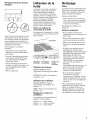
b. Utilisation d'une extension
de cheminee : Fixer les brides de
I'extension selon I'illustration.
27 cm plafond
/ i i i brides
2
1 1 1
20,6 cm 20,6 cm
(8 1/8 po_ _1 (8 1/8 po)
58,4 cm (23 po) max.
30,5 cm (12 po) m/n. sommet de la hotte
................... .X......
Veiller a ce que les vis soient
sol/dement fixees dans le mur.
= Tracer et d6couper I'ouver_ure
n6cessaire dans lemur pour le
conduit d'6vacuation. Installer le
circuit de d6charge avant la hotte. Voir
les configurations de d6charge a la
page 4.Voira la page 6 les
dimensions des ouvertures de sortie.
6

7• D_terminer la hauteur appropri_e
pour I'orifice de passage du c&b]e
d'alimentation; percer un trou de 32
mm (1 1/4 po) a cet endroit. Faire
passer le c_ble a travers le trou selon
les prescriptions du Code national des
installations _lectriques ou de la
norme CSA, ou des codes ou
r_glements Iocaux en vigueur. La
Iongueur du c_ble devra _tre
suffisante pour qu'il soit possible de
r_aliser les connexions ad_quates
dana la bofte de connexion de la hotte.
Assurer I'etanch6it_ avec un produit
de calfeutrage au niveau de chaque
ouverture.
Ne pas mettre le circuit soustension
avant d'avoir acheve rinstallation.
• Oter le couvercle de la bofte de
connexion de la hotte./_ I'aide d'un
toumevis a lame plate, arracher
I'opercule de I'orifice de passage du
c_ble d'alimentation. Installer un
connecteur de conduit clans cette
ouver_ure; la vis de bridage du
connecteur de conduit dolt _tre
I'int6rieur de la hotte.
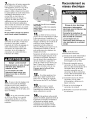
Danger - poids excessif
Deux personnes ou plus doivent
intervenir pour deplacer et
installer la hotte.
Le non-respect de cette
instruction peut causer une
btessure au dos ou d'autres
blessures,
• Si aucun vo]et de reglage n'est
associ_ a la bouche de d_charge
(murale ou sur le toit), installer le
volet de r_glage clans I'ouverture de
d_charge au sommet de la hotte, avec
deux vis Phillips.
0• Si on dolt raccorder la hotte
de 121,9cm (48 po) aun conduit
d'_vacuation de 2B,4 cm (10 po),
installer maintenant le raccord de
transition.
tringle
tour
hotte is de
montage
La hotte de 36 po (91,4 cm) comporte
deux tringles.
La hotte de 42 po (106,7 cm) comporte
quatre tringles,
La hotte de 48 po (121,9 cm) comporte
quatre tringles,
1.La hotte se fixe au mur au
moyen des vis mentionn_es a 1'6tape
5 des instructions d'installation. La
hotte est suspendue aces vis par des
tringles & I'interieur de la hotte de la
cuisini_re. Avant d'essayer de
suspendre la hotte, utiliser un
tournevis Phillips pour tourner la vis
d'ajustement marqu_eVl dans le
sens antihoraire pour d_ployer les
tringles de la hotte.
Suspendre la hotte de la cuisini_re en
ins_rant les tringles dans les vis de
montage tel qu'illustr_. Remarque :
Ces vis doivent _tre install_es dans
du bois massif pour supporter le
poids de la hotte tel que d_crit a I'_-
tape 5. Visser les vis marquees Vl
pour serrer la hotte contre lemur.
S'assurer que la hotte est fixee
solidement au tour.
2. On utilise _galement les
brides pour regler I'aplomb de la
hotte. Pour le r_glage de I'aplomb,
faire tourner les visV2 (vis Phillips).
3 • Raccorder le conduit
d'6vacuation a la hotte. Assurer
I'_tanch_it_ des jointures avec du
ruban adh_sif pour conduit.
4. si la garniture cache-conduit
(option) est utilis_e, ajuster les I_vresde
la garniture sur labride. Si I'extension
de chemin_e est utilis_e, ajuster
I'extension sur les brides. Assurer
I'_tancheit_ entre extension et hotte
avec du ruban adh_sif pour conduit.
Raccordement au
reseau electrique
Risque de choc _lectrique
Interrompre I'alimentation
electrique avant d'effectuer des
raccordernents.
Connecter le conducteur de
liaison & la terre avec la vis verte
dans la boite de connexion.
Le non-respect de ces
instructions peut provoquer un
choc _lectrique ou un accident
mortel,
5• ExScution des
raccordements _lectriques
[] Introduire le c_ble d'alimentation
darts la bofte de connexion
travers le connecteur de conduit
(homologation UL ou CSA).
[] Raccorder ensemble avec un
connecteur de ills le conducteur
blanc du c&ble d'alimentation et le
conducteur blanc de la hotte;
raccorder ensemble avec un
connecteur de ills le conducteur
noir du cable d'alimentation et le
conducteur noir de la hotte.
[] Connecter sous la vis ver_ele
conducteur vert du cable
d'alimentation, utilia_ pour la
liaison a la terre.
[] Serrer les vis de bridage du
connecteur de conduit.
[] R_installer le couvercle de la bofte
de connexion.
7

6= Installerlesfiltres.
•Sor_irlesfiltresdelaboiteetenlever
lapelliculedeprotectionblanchedes
filtres.
•SaisirI'undesfiltresdetellesorte
queleboutonaoitorient_verslehas
etversI'arrieredelahotte.
• Ins6rerI'extr_mit_dufiltrene
comportantpasleboutondansla
rainurederetenueaI'avantdela
hotte.
•Tirersurleboutonetletournervers
lagauche(aensantihoraire)detelle
sortequelelevierdeverrouillagene
fassepassailliehorsdufiltre.
• InsUrerI'extr_mitecomportantle
boutondanslarainurederetenue&
I'arri_redelahotte.
•Tournerleboutonversladroite(sens
horaire)pourverrouillerlefiltreen
place.
• R_p_terlaprocedurepourlesautres
filtres.
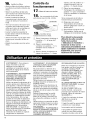
Contr61e du
fonctionnement
7= Mettre la hotte sous tension.
8= Les commandes de la hotte
sont plac_es sous la hotte, a droite.
commandes
__. _tiltres
19• Contr61er le bon
fonctionnement de la hotte.
[] Placer I'interrupteur d'_clairage
la position _ 1 _; la lampe dolt
s'allumer.
[] Placer le commutateur du
ventilateur a la position {_1 _; le
ventilateur dolt se mettre en
marche.
[] Placer le bouton de selecteur de
vitesse a la position {{ 1 >_(basse
[]
vitesse), puis _ la position _{2 >_
(vitesse moyenne), puis a la
position {{3 , (haute vitesae).
Placer les commutateurs
d'_clairage et du ventilateur a la
position _{0 >_pour commander
I'arr_t du ventilateur et I'extinction
de la lampe.
Si les composants de la hotte ne
fonctionnent pas correctement,
[] D_terminer si le circuit
d'alimentation de la hotte est
aliment_ (disjoncteur ouvert ou
fusible grill_?).
[] D_connecter la hotte du circuit
d'alimentation. V_rifier que le
c_blage a _t_ correctement r_alis&
Pour obtenir la plus grande
efficacite de cette nouvelle
hotte, lire la section
_{Utilisation et d'entretien _.
Conserver en lieu st_rles
instructions d'installation et le
Guide d'utilisation et entretien
KitchenAid, pour pouvoir
facilement les consulter.
AVERTISSEMENT - Pour reduire le
risque d'incendie ou de choc
_lectrique, ne pas utiliser ce
ventilateur en conjonetion avec un
dispositif de reglage de la vitesse
semi-conducteurs.
AVERTISSEMENT - POUR MINIMISER
LE RISQUED'INCENDIE, CHOC
ELECTRIQUEOU DOMMAGES
CORPORELS,RESPECTERLES
INSTRUCTIONS SUIVANTES :
Utiliser cet appareil uniquement de la
mani_re prevue par le fabricant. Pour
toute question, contacter le fabricant.
Avant d'entreprendre des operations
de r_paration ou nettoyage de I'ap-
pareil, interrompre I'alimentation _lec-
trique au niveau du tableau de distrib-
ution et verrouiller le disjoncteur pour
emp_cher un retablissement acciden-
tel de I'alimentation. S'il n'est pas
possible de verrouiller le disjoncteur
ou autre coupe-circuit, veiller a bien
fixer sur le tableau de distribution une
6tiquette pro_minente interdisant le
r_tablissement de I'alimentation.
MISE EN GARDE : Cet appareil est
congu uniquement pour la ventilation
generale. Ne pas I'utiliser pour
I'extraction de mati_res ou vapeurs
dangereuses ou explosives.
AVERTISSEMENT - POUR MINIMISER
LE RISQUE D'UN FEU DE GRAISSE
SUR LATABLE DECUISSON :
Ne jamais laisser un _16ment de la
table de cuisson fonctionner sans sur-
veillance a la puissance de chauffage
maximale; un renversement/d_borde-
ment de matiere graisseuse pourrait
provoquer une inflammation et le
g_#n_rationde fumee.
Utiliser toujours une puissance de
chauffage moyenne ou basse pour le
chauffage d'huile.
Veiller a toujours faire fonctionner le
ventilateur de la hotte Iors d'une cuis-
son avec une puissance de chauffage
_lev_e ou Iors de la cuisson d'un mets
flamber.
Nettoyer fr_quemment lea ventila-
teurs d'extraction. Veiller a ne pas
laiaaer de la graisae s'accumuler sur
les surfaces du ventilateur ou des fil-
tres.
Utiliser toujours un ustensile de taille
appropri_e. Utiliser toujours un usten-
sile de taille adapt_ a la taille de I'_l_-
ment chauffant.
AVERTISSEMENT - POUR REDUIRELE
RISQUEDE DOMMAGES CORPORELS
APRILSLE DECLENCHEMENT D'UN
FEU DE GRAISSE SUR LA
CUISINIt_RE,APPLIQUERLES
RECOMMANDATIONS SUIVANTES :
Placer sur le recipient un couvercle
bien ajust_, une t61ea biscuits ou
un plateau m_tallique POUR
ETOUFFERLES FLAMMES, p,uis
_teindre le brQleur.VEILLER A
EVlTERLES BROLURES. Si les
flammes ne s'_teignent pas
im,m_diatement, EVACUERLA
PIECEET CONTACTERLES
POMPIERS.
NEJAMAIS PRENDREEN MAIN UN
RI_CIPIENTENFLAMMt_ - le risque
de brQlure est _lev6.
NE PASUTILISER D'EAU ni un
torchon humide - ceci pourrait
provoquer une explosion de vapeur
brQlante. Utiliser un extincteur
SEULEMENT si :
II s'agit d'un extincteur de classe
ABC, dont on connaft le
fonctionnement.
II s'agit d'un petit feu encore limit_
I'endroit ouil s'est d_clar&
Les pompiers ont _t_ contact,s.
II est possible de garder le dos
orient_ vers une sortie pendant
I'op_ration de lutte contre le feu.
8
La page est en cours de chargement...
La page est en cours de chargement...
La page est en cours de chargement...
La page est en cours de chargement...
-
 1
1
-
 2
2
-
 3
3
-
 4
4
-
 5
5
-
 6
6
-
 7
7
-
 8
8
-
 9
9
-
 10
10
-
 11
11
-
 12
12
-
 13
13
-
 14
14
-
 15
15
-
 16
16
-
 17
17
-
 18
18
-
 19
19
-
 20
20
-
 21
21
-
 22
22
-
 23
23
-
 24
24


KitchenAid KWCU360JSS0 Le manuel du propriétaire
- Catégorie
- Hottes
- Taper
- Le manuel du propriétaire
- Ce manuel convient également à
dans d''autres langues
Documents connexes
-
KitchenAid 36 Manuel utilisateur
-
-
-
-
-
-
-
-
-
