
(.5
(.5
23(5$7,1*,16758&7,216
%(75,(%6$1/(,781*
0$18(/',6758&7,216


Pag. 1 MNNAEKR_0408
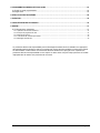
INDEX
1 INTRODUCTION .......................................................................................................................................................3
1.1 Contents of the package .....................................................................................................................................3
1.2 Contents of this Instruction Manual.....................................................................................................................3
1.3 Typographical conventions .................................................................................................................................3
1.4 Safety rules .........................................................................................................................................................4
1.5 Identification data ................................................................................................................................................4
2 EKR-8/4 / EKR-16/4 MATRIX DESCRIPTION..........................................................................................................5
2.1 Specifications ......................................................................................................................................................5
2.2 Connectable devices...........................................................................................................................................5
3 INSTALLATION ........................................................................................................................................................6
3.1 Preliminary operations ........................................................................................................................................6
3.1.1 Opening the package.....................................................................................................................................................6
3.1.2 Checking the markings ..................................................................................................................................................6
3.2 Installation example ............................................................................................................................................6
3.2.1 Cables............................................................................................................................................................................7
3.3 Switching on and off............................................................................................................................................7
3.4 Configuration.......................................................................................................................................................8
3.4.1 Opening and closing ......................................................................................................................................................8
Dip switches and jumper.........................................................................................................................................................8
3.4.3 Inserting the load on the AUX line..................................................................................................................................9
3.4.4 Setting 75 Ohm video input termination .........................................................................................................................9
3.5 Connectors and connections.............................................................................................................................10
3.5.1 Connectors on the back of the matrix ..........................................................................................................................10
3.5.2 DB25 pin configuration.................................................................................................................................................10
3.5.3 Connections for alarm management ............................................................................................................................11
3.5.4 Connecting the matrix to the peripherals .....................................................................................................................11
4 MATRIX OPERATING FEATURES ........................................................................................................................14
4.1 Video input management ..................................................................................................................................14
4.1.1 Automatic switching sequences...................................................................................................................................14
4.1.2 Day and night automatic switching sequences ............................................................................................................14
4.1.3 Manual selection..........................................................................................................................................................14
4.1.4 Using the Inc/Dec keys ................................................................................................................................................14
4.1.5 Output video dedicated to the VCR..............................................................................................................................14
4.2 Alarms ...............................................................................................................................................................15
4.2.1 Alarm contact types .....................................................................................................................................................15
4.2.2 Alarm types..................................................................................................................................................................15
4.2.3 Alarm condition reset ...................................................................................................................................................16
4.2.4 Alarm recognition enabling ..........................................................................................................................................16
4.3 Actions on alarms..............................................................................................................................................17
4.3.1 Action to switch videos.................................................................................................................................................17
4.3.2 Action to reposition telemetry.......................................................................................................................................17
4.3.3 Changing the actions ...................................................................................................................................................17
4.4 Excluding video inputs ......................................................................................................................................18
4.4.1 How to exclude the video inputs ..................................................................................................................................18
4.5 Auxiliary line ......................................................................................................................................................20
4.5.1 Control keyboard configuration ....................................................................................................................................20
4.5.2 Video multiplexer control..............................................................................................................................................20
4.5.3 Telemetry receiver control and domes.........................................................................................................................20
4.6 Telemetry protocol ............................................................................................................................................21
4.6.1 Configuring the dome...................................................................................................................................................21
4.6.2 Configuring the switcher/matrix....................................................................................................................................21
4.6.3 Configuring the keyboard.............................................................................................................................................21
4.7 Telemetry transmission over coaxial cable .......................................................................................................22
4.8 PC connection...................................................................................................................................................22

Pag. 2 MNNAEKR_0408
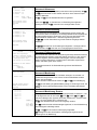
5 ON SCREEN MENU (OSM) PROGRAMMING.......................................................................................................23
5.1 Programming entering.......................................................................................................................................23
5.2 Screens .............................................................................................................................................................23
6 TROUBLESHOOTING ............................................................................................................................................28
7 MAINTENANCE ......................................................................................................................................................30
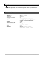
8 TECHNICAL SPECIFICATIONS.............................................................................................................................30
9 APPENDIX...............................................................................................................................................................31
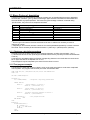
9.1 Macro Protocol: description...............................................................................................................................31
9.1.1 Checksum calculation procedures ...............................................................................................................................31
9.1.2 Test program example .................................................................................................................................................31
9.1.3 Reply from the matrix...................................................................................................................................................32
9.1.4 Matrix control commands.............................................................................................................................................32
9.1.5 Event messages ..........................................................................................................................................................32
The manufacturer assumes no responsibility for possible damages resulting from an improper use of the devices mentioned
in this manual; moreover he reserves the right to change the contents of the present manual without notice. The
documentation contained in this manual has been gathered and examined with great care; nevertheless the manufacturer
can not assume any responsibility resulting from the use of such documentation. The same is valid for any other person or
society involved in the creation and in the production of the present manual.

Pag. 3 MNNAEKR_0408
1 Introducti on
1.1 Contents of the package
• 1 programmable video matrix EKR-8/4 / EKR-16/4
• 1 instruction manual
• 1 wide range power supply 100 - 240V~ 47/63Hz in, 12V
= 1A out, including cables
• 1 DB25 connector
• 2 telephone boxes RJ-jack
• RJ11 telephone cables, 6 pins point-to-point
When the product is delivered make sure the package is intact and has no obvious signs of dropping, scrapes
and scratches. If the package is damaged contact the supplier immediately.
1.2 Contents of this Instruction Manual
This manual describes the video switcher EKR-8/4 / EKR-16/4, with its specific procedures for installation,
configuration and use. Before installing and using the video switcher, read this manual carefully,
especially the section concerning the safety rules.
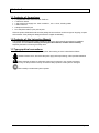
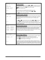
1.3 Typograp hical conventions
This manual makes use of different graphics symbols, the meaning of which is described as follows:
Hazard of electric shock; disconnect the power supply before proceeding, unless specified otherwise.
Please read the procedure or information shown and, if necessary, carry out the instructions.
Failure to carry out the procedure correctly could lead to faulty operation of the system or damage it.
Read carefully to understand system operation.

Pag. 4 MNNAEKR_0408
1.4 Safety rul es
The video switcher EKR-8/4 / EKR-16/4 complies with the legislation and standards in force, at the time
of this manual’s publication, with regard to electrical safety, electromagnetic compatibility and general
requirements. Nevertheless, for the safety of the user (installer technician and operator) the following warnings
are specified to ensure completely safe operation:
• Connect the system devices to a power supply line corresponding to the one shown on the respective data
plates (see the following section 1.5 Identification data).
• The device (and the complete system to which it belongs) must only be installed by a skilled, authorised
technician.
• For after-sale service call only authorised staff.
• The device should never be opened, but if this becomes necessary the procedures described in this manual
should be followed scrupulously.
• Do not unplug the device by pulling the power supply cable.
• Before moving or carrying out any technical operations on the device, disconnect the power supply jack: the
device can only be considered off-line when the power supply jack is disconnected and the cables connected
to other devices have been removed.
• Do not use extension cables showing signs of wear or ageing, since they are extremely hazardous for the
user’s safety.
• Do not wet the device with any liquid or touch it with wet hands while it is in operation.
• Do not leave the device exposed to adverse weather conditions.
• Do not use the device in the presence of inflammable substances.
• Make sure the device is always resting on a sufficiently large, solid base.
• Tampering with the device will invalidate the guarantee.
• Keep this manual carefully for future reference.
1.5 Identifica tion data
On the bottom of the video matrix EKR-8/4 / EKR-16/4 there are two identification plates complying with EC
specifications.
The first plate contains:
• Model identification code (Bar code EXT3/9)
• Main supply voltage (Volt)
• Frequency (Hertz)
• Maximum power consumption (Watt)
The second plate shows the model serial number (Bar code EXT3/9)
Warning! When carrying out installation make sure that the power supply to the matrix corresponds to
the required specifications. Use of inappropriate equipment may be very hazardous for the safety of personnel
and of the system itself.

Pag. 5 MNNAEKR_0408
2 EKR-8/4 / EKR-16/4 matrix description
2.1 Specifica tions
The EKR-8/4 / EKR-16/4 matrix is a product for professional use in applications for security and
surveillance. In a security system it is used to control 8/16 video inputs on 4 outputs, using remote keyboards.
The following is a list of its main features:
• Video programming
• Menu in four languages (Italian, English, French and German)
• Different switching sequences (day and night) for each output video
• Date and time management settable from the user
• VCR trigger management
• Telemetry control on RS485 auxiliary line and on coaxial cable
• Matrix control using 4 serial RS485 lines for remote control devices
• Identification tests for each output
• Completely configurable alarm input for each input video
• Types of alarm reset: manual from keyboard, external, timed, automatic
• Relay can be activated by each alarm
• Alarm condition warning buzzer
• Video signal masking on fixed camera
• RS322 serial line for the PC control
• 75 Ohm video input termination removable
• Video switching or reposition in case of alarm
• Video input exclusion from switching sequence on public monitors
2.2 Connecta ble devices
Keyboards:
Connect a max. of 4 keyboards using the KEYBOARDS lines:
• new series MTC-1: used for complete matrix control
Telemetry receivers:
Control of telemetry receivers using the AUX line:
• Videotec receivers DTMRX1, DTRX3, DTRX1, DTRXDC, MICRODEC485, DTMRX2
• Dome with protocol Pelco ‘D’
• Eneo receivers
Control of telemetry receivers using the video lines (COAX transmission):
• Videotec receivers DTRX3 fitted with a DTCOAX, DTMRX2 board
Multiplexer videos
• Multiplexer Javelin color
• Multiplexer Javelin B/W
• Multiplexer Eneo color
• Multiplexer Eneo B/W
• Multiplexer Videotec SP16C

Pag. 6 MNNAEKR_0408
3 Installatio n
The following procedures should be carried out before connecting to the power supply, unless indicated
otherwise.
Installation should only be carried out by skilled, authorised technicians. Incorrect connection of the
various peripherals may lead to isolation of the video switcher from the whole system.
3.1 Prelimina ry operations
3.1.1 Opening th e package
If the package has no obvious defect due to dropping or abnormal scrapes and scratches, check the materials it
contains with the list supplied in Section 1.1 Contents of the package.
The installer technician will be responsible for disposing of the packaging material by recycling or, in any case,
according to the current legislation in the country of use.
3.1.2 Checking th e markings
Before starting installation, check the identification plates to make sure the supplied material
corresponds with the required specifications, as described in Section 1.5 Identification data. Never, under any
circumstances, make any changes or connections that are not described in this manual: the use of inappropriate
devices may be very hazardous for the safety of people and the system itself.
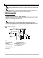
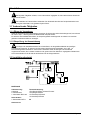
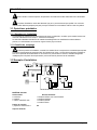
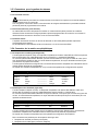
3.2 Installatio n example
MATERIAL USED:
Video management: Telemetry management:
2 monitors 1 Receiver DTRX3 with DTCOAX board
2 cameras 1 DTMRX1 receiver
1 video matrix EKR-16/4 1 Pan&Tilt motor PTH910P
1 Pan&Tilt motor PTH910
Control keyboards:
1 MTC-1 control keyboard PC
Alarm sensor

Pag. 7 MNNAEKR_0408
3.2.1 Cables
Cable for transmission/reception of commands: unshielded twisted pair with minimum section
0.22 mm² (AWG 24):
• a pair for RS485 transmission both for KEYBOARD lines and AUX lines (max. length of connection 1200m.)
• a pair for powering the keyboards, which can be remote powered (max. length of connection 700m.)
Cable for DB25 connector: multi-polar cable with minimum section 0.22 mm² (AWG 24)
Video cable: RG59 coaxial cable or equivalent
as well as being used for video transmission it can also be used for transmitting telemetry data (in this case the
max. length of the connection is 350m)
Multi-polar cable:
every pan & tilt control function is enabled/disabled by a relay inside the receiver.
• To determine the final number of wires, follow the instructions below:
• 7 wires for the pan & tilt movements (230 V~ o 24 V~): right, left, up, down autopan, common, ground (only
for 230 V~)
• 6 wires for reverse polarity lens control (zoom, focus, iris)
• 4 wires for common wire lens control (zoom, focus, iris)
• 7 wires for preset management: 5 connected to reference potentiometers, +5 V
= and ground
• 4 wires for the Wiper
• 3 wires for the Washer
• 2 wires for each auxiliary used
• 3 wires for power supply cable
Note: we recommend using different multi-polar cables for low and high voltage functions.
Recommended minimum section: 0.56 mm² (AWG 20) for high voltage wires (pan & tilt, wiper, washer)
0.34 mm² (AWG 22) for low voltage wires (lenses, auxiliaries, preset)
0.75 mm² (AWG 18) for power supply wires to the DTRX1 receiver
PC cable: 9 poles- standard serial extension cable (max 15m)
3.3 Switching on and off
Before connecting to the power supply:
• Make sure the supplied material corresponds to the required specifications by examining the identification
plates as described in section 1.5 Identification Data
• Make sure the matrix and other components of the system are closed properly so that there is no possibility
of direct contact with live parts
• The matrix and other devices in the system should rest on a large, solid base.
• The power supply cables should not get in the way of the installer technician when he is carrying out normal
operations
• Make sure the power outlet and extension cables, if used, are sufficient for the system power consumption.
SWITCHING ON: insert the power supply plug in the power outlet and connect the corresponding jack
to the matrix connector labelled 12VDC. The front side led must be lighted.
SWITCHING OFF: remove the external power supply plug from the power outlet and disconnect the
jack from the matrix.

Pag. 8 MNNAEKR_0408
3.4 Configura tion
3.4.1 Opening an d closing
Warning! Only skilled, authorised technicians should be allowed to open the matrix.
• Disconnect the matrix from the main power supply by disconnecting the jack
• Remove the three screws on the back of the matrix, behind the top cover
• Remove the cover, taking great care not to leave the removed screws or other metal parts inside the matrix
and being very careful with the LED wiring.
To close up, carry out the above operations in reverse order, always working with the power supply
disconnected.
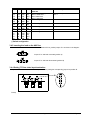
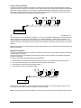
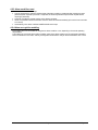
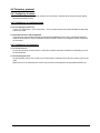
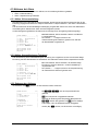
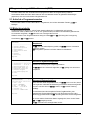
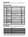
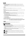
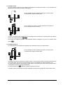
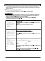
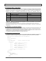
3.4.2 Dip switche s and jumper
3.4.2.1 Functions of the dip switches
Inside the EKR-8/4 / EKR-16/4 matrix there is an 8-way configuration dip switch (SW1):
DIP FUNCTION
DIP 1,2,3,4 Selection of protocol for communication with the keyboards; see section 3.4.2.2
DIP 5 Not used: leave OFF
Dip 6 Not used: leave OFF
Dip 7,8 If on ON position, they allow the matrix firmware update; see section 4.8
If on OFF position, they allow the PC control: normally set on OFF
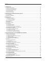
3.4.2.2 Selecting the protocol for communication with the keyboards
Switch off the matrix by disconnecting the power supply jack
• Remove the screws fastening down the cover and open the matrix, following the instructions in section 3.4.1
• Find and set the dip-switches according to the table below
• Close the cover and fasten it with the screws
• Connect the power supply jack to switch the matrix back on.
Note: all changes to the dip-switches are recognised when the matrix is restarted
Jumper JP11
Dip Switch SW1
Jumper 75 ohm
Video input

Pag. 9 MNNAEKR_0408
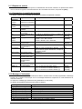
Dip switch
1234Protocol and
baud rate
Connected keyboards
OFF
OFF
OFF
OFF
OFF
OFF
OFF
OFF
OFF
OFF
ON
ON
OFF
ON
OFF
ON
Macro, 38400 baud (*)
Macro, 19200 baud
Macro, 9600 baud
Macro, 1200 baud
New series keyboards:
MTC-1
OFF
OFF
ON
ON
OFF
OFF
OFF
ON
Invalid configurations
OFF
OFF
ON
ON
ON
ON
OFF
ON
Invalid configurations
ON
ON
OFF
OFF
OFF
OFF
OFF
ON
Invalid configurations
ON OFF ON OFF Invalid configurations
ON
ON
ON
ON
ON
OFF
ON
ON
ON
ON
ON
OFF
OFF
ON
ON
ON
OFF
ON
OFF
ON
Invalid configurations
(*)Default configuration
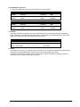
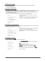
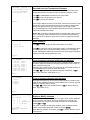
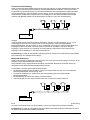
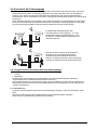
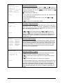
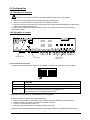
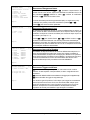
3.4.3 Inserting th e load on the AUX line
To insert/disconnect the 120 Ohm load on the RS485 AUX line, position jumper JP11 as shown in the diagram:
Jumper JP11 with load connected (position A)
Jumper JP11 with load disconnected (position B)
3.4.4 Setting 75 O hm video input termination
It’s possible to remove the 75 Ohm video input termination putting the corresponding jumper into position B.
Example: input 1-2-3 without load

Pag. 10 MNNAEKR_0408
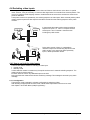
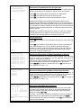
3.5 Connecto rs and connections
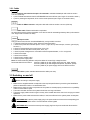
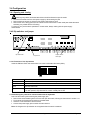
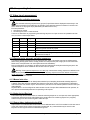
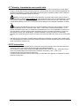
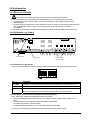
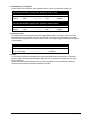
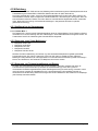
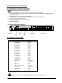
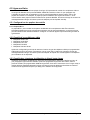
3.5.1 Connectors on the back of the matrix
The back of the EKR-8/4 / EKR-16/4 matrix has:
• 1 x 25 pin connector for connecting alarm contacts, relay contacts, VCR trigger and external alarm reset
• 4 x RJ-11 connectors for connecting the keyboards
• 1 x RJ-11 connector for connecting the telemetry receivers or multiplexers
• 1 jack connector for the power supply
• 1 x 9 pin connector for PC connection
• 4 BNC output video connectors,
• 8/16 BNC input video connectors
EKR-16/4 matrix rear view:
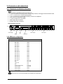
3.5.2 DB25 pin c onfiguration
Pin Connection Use
1 Alarm input 1 Alarms
2 Alarm input 2 Alarms
3 Alarm input 3 Alarms
4 Alarm input 4 Alarms
5 Alarm input 5 Alarms
6 Alarm input 6 Alarms
7 Alarm input 7 Alarms
8 Alarm input 8 Alarms
9 Alarm input 9 Alarms
10 Alarm input 10 Alarms
11 Alarm input 11 Alarms
12 Alarm input 12 Alarms
13 Alarm input 13 Alarms
14 Alarm input 14 Alarms
15 Alarm input 15 Alarms
16 Alarm input 16 Alarms
17 Alarm reset Alarm reset
18 GND Alarm reset
19 Trigger VCR VCR
20 GND VCR
21 Normally Opened Relays Peripherals
22 Common Relays Peripherals
23 Common alarms Alarms
24 Common alarms Alarms
25 Common alarms Alarms
Alarms from 9 to 16 are only available on the EKR-16/4 model matrix.
PC
Power supply
Alarms
A
ux
Line
Keyboards
Video out
p
uts Video In
p
uts

Pag. 11 MNNAEKR_0408
3.5.3 Connection s for alarm management
See pin configuration table for the DB25 connector.
3.5.3.1 Alarm contac ts
WARNING! Do not energise the alarm contacts! The sensors (or the alarm system in use) should supply
a dry contact. To manage the alarms correctly, be very careful when configuring the alarm parameters at the
matrix programming stage.
3.5.3.2 Auxiliary con tact (alarm relay)
The EKR-8/4 / EKR-16/4 matrix can be used to control an auxiliary contact (relay) that is activated when there is
an alarm, if properly configured at the matrix programming stage. The auxiliary relay contacts are at pins 21 and
22 of the DB25 connector.
3.5.3.3 External rese t
The reset impulse is recognised on the falling or rising edge (which can be set at the matrix programming
stage).
Pin 17 of the DB25 connector is associated with External Reset of the alarm condition and the ground reference
is pin 18.
3.5.4 Connecting the matrix to the peripherals
3.5.4.1 Control keybo ards (Keyboard lines)
All the keyboards specified in section 2.2 Connectable devices and the EKR-8/4 / EKR-16/4 video matrix can be
connected by telephone cable using the 4 RJ-11 sockets called KEYBOARDS.
They can be connected directly using the 1.5m cable (supplied with the control keyboards) for short distances,
or, for longer distances, using the RJ-jack wall-mounted boxes (supplied with the control keyboards).
All the keyboards should have transmission rate settings that are compatible with the settings made for the
matrix at the programming stage. See the respective manuals for the keyboard setup.
Connecting RS 485 KEYBOARD lines
MATRIX RJ-jack 1 RJ-jack 2 KEYBOARDS
RS485-A Blue ----------------- White RS485-A
RS485-B Black ----------------- Yellow RS485-B
12 VDC Red
GND Green
3.5.4.2 Telemetry rec eivers (AUX line)
All the receivers specified in section 2.2 Connectable devices and the EKR-8/4 / EKR-16/4 video matrix can be
connected by telephone cable using the RJ-11 socket called AUX.
They can be connected directly using the 1.5m cable (supplied by the manufacturer) for a test or, for longer
distances, using the RJ-jack wall-mounted boxes (supplied by the manufacturer) and referring to the following
table:
RS 485 matrix (AUX line) – Receiver connection
MATRIX RJ-jack 1 RJ-jack 2 RECEIVER
RS485-A White ----------------- Blue RS485-A
RS485-B Yellow ----------------- Black RS485-B
All the receivers should be set up for RS485 communication mode and with a transmission rate that is
compatible with the setting made for the matrix at the programming stage.
See the respective manuals for configuring the receivers.
There are two possible ways of connecting the receivers to the AUX line:
• Receivers in cascade (Point-to-point connection)
• Receivers on the same line (Multi-point connection)

Pag. 12 MNNAEKR_0408
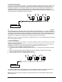
Point to point connection
This type of connection allows the AUX line to be used to control one or more receivers arranged in cascade
(point-to-point type connection). The AUX line of the matrix should have the termination resistance inserted (see
section 3.4.3). Each receiver in turn should have a RS485 line termination resistance inserted. Each receiver
should have a different address. Configure the receivers with RS485 type communication with the same baud
rate and protocol (Videotec or MACRO) as the Matrix AUX line.
Internally, the receivers can regenerate the received signal and send it on along a new communication line to
the next receiver. Each of the three line sections (L1, L2, L3) is considered independent, and connects only two
devices point-to-point, both with the load inserted, for a maximum distance of 1200 metres. The Matrix - R3
receiver distance can therefore be up to 3600 m (1200 m between the Matrix Aux line and receiver R1, 1200 m
between receiver R1 and receiver R2, and a further 1200 m between receiver R2 and receiver R3, for a total of
3600 m).
N.B. For the connection in question (point-to-point), faulty operation of one of the devices will cause faults in the
receivers that follow.
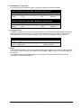
Multipoint connection
This type of connection allows the AUX line to be used to control one or more receivers connected on the same
line (multi-point connection).
Connect the receiver on the RS485 communication line with the same AUX matrix line baudrate and protocol
(Videotec or MACRO).
For each line the following should be taken into consideration:
• the Aux Matrix line should have the load inserted (see section 3.4.3 Inserting the load on the AUX line)
• only one of the receivers (the one at the end of the line) has the load inserted.
• the total length of the line should not exceed 1200 m.
• each receiver should have a different address
Receivers R1, R2 should not have the termination resistance inserted. The maximum length of the line, from
end to end (from the matrix AUX line to receiver R3), is 1200 metres.
N.B. For the connection in question (multipoint), a fault in one of the devices does not affect the other receivers.

Pag. 13 MNNAEKR_0408
3.5.4.3 Multiplexer (A UX line)
For the type of Multiplexer to be used, see the following connection tables
Matrix (AUX line) –Javelin - Eneo Multiplexer RS 485 connection
MATRIX RJ-jack 1 RJ-jack 2 Mux
RS485-A White ----------------- Black RS485-A
RS485-B Yellow ----------------- Green RS485-B
Matrix (AUX line) –SP16C Videotec Multiplexer RS 485 connection
MATRIX RJ-jack 1 RJ-jack 2 Mux
RS485-A White ----------------- Black RS485-A
RS485-B Yellow ----------------- Yellow RS485-B
3.5.4.4 VCR
The Trigger impulse is recognised on the rising or falling edge which can be set at the matrix programming
stage. Connect the VCR input video with output video n°4 of the matrix (VCR dedicated output). For the VCR
trigger on the other hand, refer to the following connection table:
Matrix – VCR connection
Matrix DB25 VCR
Pin 19 – Trigger ------------------------- Trigger pin
Pin 20 – Ground GND ------------------------- Ground pin
3.5.4.5 PC
It is possible to connect a PC for remote control of the matrix or for the firmware update using a standard 9-pin
serial extension cable (DB9M - DB9F) and connecting it to the matrix DB9 (“PC”) socket.
If the Macro communication protocol, given in the appendix, is used it is possible to completely control the
matrix and record noteworthy events when necessary.

Pag. 14 MNNAEKR_0408
4 Matrix op erating features
4.1 Video inp ut management
4.1.1 Automatic switching sequences
The automatic switching sequences are groups of input videos that are displayed consecutively in the
order and for the length of time defined by the operator. Each switching sequence consists of a minimum of 1
and a maximum of 16 program steps (identified by the letters from A to P).
Each step describes:
• the input to be viewed
• the viewing time, from 1 to 300 seconds.
There are no restrictions to programming the switching sequence: an input can even be repeated more than
once, as shown in the example below:
Step Input Length
Comment
A
1 2 Input 1 is on view for 2 seconds
B
2 4 Input 2 for 4 seconds
C
5 7 Input 5 for 7 seconds
D
- - - Step D is ignored and will be jumped
E
2 5 Input 2 is on view again for 5 seconds
F-P
- - -
If there are no further program steps, the automatic switching sequence
will resume from step A.
4.1.2 Day and nig ht automatic switching sequences
Two different switching sequences can be defined for each outlet. This makes control of the infrastructures
easier during the day (when there is usually personnel on the premises) and at night (when control would be
better on the outer perimeter or at critical points around the installation).
During configuration, it is necessary to define the start and end times of the daytime switching sequence: the
night-time sequence will be enabled for the rest of the 24-hour period.
Warning! If the night-time sequence is not used (only one automatic viewing sequence is defined for the
whole 24-hour period), the start and end of the daytime switching sequence should be defined as 00:00 and
23:59 respectively. If the matrix seems to have an operating fault this may be due to an error in configuring the
daytime sequence start /end time.
4.1.3 Manual sele ction
From the keyboard, the operator can directly select a desired input, interrupting the automatic switching sequence.
A specific input video is always selected with reference to the active monitor: if the keyboard is authorised to
control more than one monitor only the “active monitor” (the last one to be selected) will be involved in the input
video selection.
Keyboard MTC-1 can be configured to restrict access to a set of output videos dedicated to each operator, so
as to prevent unauthorised personnel from operating on all outputs.
4.1.4 Using the In c/Dec keys
The Inc/Dec keys can be used to block an automatic switching sequence on one input and, where appropriate,
to select the next/previous input video (following the preset order for the switching sequence in progress)
without having to use the numeric keypad to select an input.
4.1.5 Output vide o dedicated to the VCR
Output video n°4 of matrices EKR-8/4 and EKR-16/4 is dedicated to the VCR if it is enabled. In this case control
of the VCR channel is only subject to the trigger impulse itself. Any command that may be sent from the
keyboard concerning this channel will therefore be ignored.

Pag. 15 MNNAEKR_0408
4.2 Alarms
The matrix provides a DB25 alarm connector, to which 8/16 (depending on the EKR-8/4 / EKR-16/4
model) alarm contacts ("alarm input") can be attached, one for each of the input videos of the video device.
When an alarm is activated:
• the keyboards able to display the alarm condition can activate a warning buzzer and may also show the
alarm status with a display message or a flashing LED (this type of operation is determined by the
characteristics and configuration of the individual keyboard).
• each output that is enabled for recognition shows the video signal corresponding to the latest recognised
alarm in order of time; if an output is not enabled for recognition of the alarm condition, the alarm will not be
shown on the video
• the alarm relay will be closed (auxiliary contact) and in some cases a warning buzzer is activated inside the
matrix, if this is allowed for by the alarm contact configuration
• the text identifying the corresponding input is accompanied by the word “ALARM”.
Alarm status will be stored internally and will be kept, even if there is a temporary interruption to the matrix
power supply. Warning! The alarms must be configured with special care, because a mistake in their settings
could cause faults in operation that are difficult to identify.
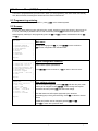
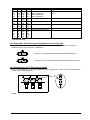
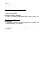
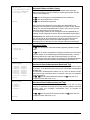
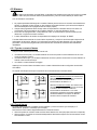
4.2.1 Alarm cont act types
Each individual alarm contact can be defined:
• normally open (N.O.): the alarm condition is recognised when the alarm contact is short circuited to the
common alarm pin
• normally closed (N.C.): the alarm condition is recognised when there is a break in the contact between the
alarm and common alarm pin
• not used: the alarm contact is ignored.
Warning! Pins that are not connected to any alarm contact should be configured as NOT USED.
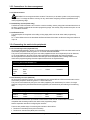
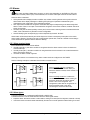
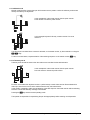
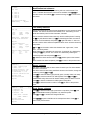
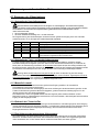
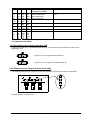
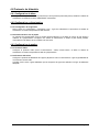
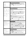
See the following example to understand how the alarm contacts function:
Alarms normally open: the contacts are
disconnected from the common alarm pin.
When the contact is closed, alarm number 3 is
recognised.
Alarms normally closed: the contacts are
connected to the common alarm contact (pin
23-24-25). When the connection opened,
alarms 1 and 3 are recognised. This
configuration is also able to recognise as an
alarm a possible break in the cable
connecting the sensor and the matrix.
4.2.2 Alarm type s
The alarm signal can be considered CONTINUOUS or IMPULSIVE.
The difference lies in how the matrix behaves when the alarm signal ceases:
• impulsive alarm: the matrix remains in alarm status, waiting for a reset (from the keyboard, external or timed)
• continuous alarm: the matrix resets automatically and returns to normal operation without waiting for a reset.

Pag. 16 MNNAEKR_0408
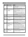
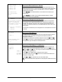
4.2.3 Alarm cond ition reset
The alarm can be reset in four ways:
• from the keyboard: the operator requests reset of the alarm condition, sometimes after inserting the reset
password (when required by the MTC-1 keyboard; the other keyboards accept the reset request without
requiring a password)
• externally: activated by a reset contact on the alarms connector
• timed: it is possible to select a time after which the alarm will reset automatically (this can be from 2 seconds
to 12 hours)
• automatically, if the alarm is defined CONTINUOUS and it stops
4.2.4 Alarm reco gnition enabling
Each output video can be enabled to recognise an alarm condition or not, depending on its actual operating
requirements.
The outputs not concerned with an alarm condition (each of the alarm contacts can be configured individually)
show no indication on the video, and only the keyboard will be able to notify an abnormal situation as it occurs.

Pag. 17 MNNAEKR_0408
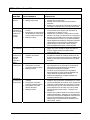
4.3 Actions o n alarms
For each alarm a pair of actions have been defined, to make alarm management more flexible:
• action to switch videos
• action to reposition telemetry.
4.3.1 Action to s witch videos
When there is an alarm event, the camera corresponding to the active alarm number is normally offered to all
monitors enabled for acknowledge: camera 1 corresponds to alarm 1, camera 2 to alarm 2 etc.
If it is necessary to switch a different video input from the standard, it is possible to request differentiated
switching using the action on alarm.
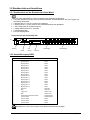
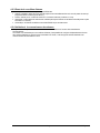
The screen for configuring each alarm shows a summary of the corresponding action:
[ALARM NO.1 5]
[----------------------------]
[ 1.Type: Normally Open ]
[ 2.Reset: Cont ]
[ 3.Relay activation: YES ]
[ 4.Buzzer activation: NO ]
[ 5.Acknowledge: 1,2,3,4 ]
[ 6.Action: CO4:MO2,R01:P03 ]
[ ]
[INC.Next Alarm ]
[DEC.Previous Alarm ]
[SEQ.End ]
C04:M02 means that, in the event of alarm 1, camera 4 is
switched to monitor 2.
The script C--:M-- means that the video switching action is
not used and normal operation therefore is expected.
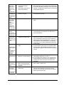
4.3.2 Action to re position telemetry
If control of a telemetry line on the Aux line is provided, it is possible to reposition a pan & tilt or a dome on a
particular preset position in the event of an alarm:
[ALARM NO.1 5]
[----------------------------]
[ 1.Type: Normally Open ]
[ 2.Reset: Cont ]
[ 3.Relay activation: YES ]
[ 4.Buzzer activation: NO ]
[ 5.Acknowledge: 1,2,3,4 ]
[ 6.Action: CO4:MO2,R01:P03 ]
[ ]
[INC.Next Alarm ]
[DEC.Previous Alarm ]
[SEQ.End ]
R01:P03 means that, in the event of alarm 1, pan & tilt/dome
number 1 is repositioned to preset position 3.
The script R--:P-- means that the telemetry repositioning
action is not used.
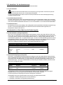
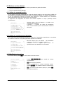
4.3.3 Changing t he actions
From the alarm menu press to enter the Action submenu.
[ACTION ON ALARM 1 5.6]
[----------------------------]
[ VIDEO ]
[ 1.Show Camera 4 ]
[ 2.on Monitor 2 ]
[ ]
[ TELEMETRY ]
[ 3.On Receiver 1 ]
[ 4.call Position 3 ]
[ ]
[CLEAR.Erase action ]
[SEQ.End ]
Press ,,, to change the corresponding
item.
deletes the action settings.
During modification the item concerned flashes: press
/ to change the value and confirm with , or
insert the number directly when possible (e.g. press
to
insert the number 3).

Pag. 18 MNNAEKR_0408
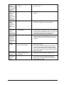
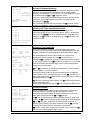
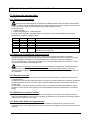
4.4 Excluding video inputs
Normally, switching a video signal on a monitor does not influence what is shown on the others. In special
cases, however, it may be necessary to remove a video signal when it is controlled from a remote position. This
occurs, for example, inside shopping centres or outside banks where some of the monitors are shown to the
public as deterrents.
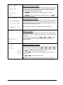
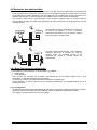
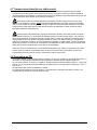
These public monitors are permanently in a switching sequence of video inputs. When a remote position (called
master) requires a particular video input this should be removed from the switching sequence of the public
monitors:
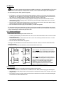
In the example the master monitor shows a switching
sequence on inputs 1, 2, 3 and 4. The public monitor
shows inputs 1 and 2. Camera 1 frames the area
including the public monitor.
During active control of input 1 it is advisable to
remove this input from the switching sequence on the
public monitor. In this case it has been replaced by
input 5, called replacement camera.
4.4.1 How to exc lude the video inputs
There are two different modes for excluding the video input:
• manual mode
• telemetry mode
In both cases the camera is excluded only if the public monitors are in automatic switching sequence. The
master monitor is always number 1.
Exclusion does not concern any dedicated output to the VCR.
During exclusion the master monitor shows an advisory message. This message is removed by any alarm
message.
4.4.1.1 Configuration
The exclusion mode is selected in 2.System configuration by selecting 8.Video.
After selecting the appropriate exclusion mode, indicate which replacement camera is to be used.
See chapter 5 “On Screen Menu (OSM) Programming”.
La page est en cours de chargement...
La page est en cours de chargement...
La page est en cours de chargement...
La page est en cours de chargement...
La page est en cours de chargement...
La page est en cours de chargement...
La page est en cours de chargement...
La page est en cours de chargement...
La page est en cours de chargement...
La page est en cours de chargement...
La page est en cours de chargement...
La page est en cours de chargement...
La page est en cours de chargement...
La page est en cours de chargement...
La page est en cours de chargement...
La page est en cours de chargement...
La page est en cours de chargement...
La page est en cours de chargement...
La page est en cours de chargement...
La page est en cours de chargement...
La page est en cours de chargement...
La page est en cours de chargement...
La page est en cours de chargement...
La page est en cours de chargement...
La page est en cours de chargement...
La page est en cours de chargement...
La page est en cours de chargement...
La page est en cours de chargement...
La page est en cours de chargement...
La page est en cours de chargement...
La page est en cours de chargement...
La page est en cours de chargement...
La page est en cours de chargement...
La page est en cours de chargement...
La page est en cours de chargement...
La page est en cours de chargement...
La page est en cours de chargement...
La page est en cours de chargement...
La page est en cours de chargement...
La page est en cours de chargement...
La page est en cours de chargement...
La page est en cours de chargement...
La page est en cours de chargement...
La page est en cours de chargement...
La page est en cours de chargement...
La page est en cours de chargement...
La page est en cours de chargement...
La page est en cours de chargement...
La page est en cours de chargement...
La page est en cours de chargement...
La page est en cours de chargement...
La page est en cours de chargement...
La page est en cours de chargement...
La page est en cours de chargement...
La page est en cours de chargement...
La page est en cours de chargement...
La page est en cours de chargement...
La page est en cours de chargement...
La page est en cours de chargement...
La page est en cours de chargement...
La page est en cours de chargement...
La page est en cours de chargement...
La page est en cours de chargement...
La page est en cours de chargement...
La page est en cours de chargement...
La page est en cours de chargement...
La page est en cours de chargement...
La page est en cours de chargement...
La page est en cours de chargement...
La page est en cours de chargement...
La page est en cours de chargement...
La page est en cours de chargement...
La page est en cours de chargement...
La page est en cours de chargement...
La page est en cours de chargement...
La page est en cours de chargement...
La page est en cours de chargement...
La page est en cours de chargement...
La page est en cours de chargement...
La page est en cours de chargement...
-
 1
1
-
 2
2
-
 3
3
-
 4
4
-
 5
5
-
 6
6
-
 7
7
-
 8
8
-
 9
9
-
 10
10
-
 11
11
-
 12
12
-
 13
13
-
 14
14
-
 15
15
-
 16
16
-
 17
17
-
 18
18
-
 19
19
-
 20
20
-
 21
21
-
 22
22
-
 23
23
-
 24
24
-
 25
25
-
 26
26
-
 27
27
-
 28
28
-
 29
29
-
 30
30
-
 31
31
-
 32
32
-
 33
33
-
 34
34
-
 35
35
-
 36
36
-
 37
37
-
 38
38
-
 39
39
-
 40
40
-
 41
41
-
 42
42
-
 43
43
-
 44
44
-
 45
45
-
 46
46
-
 47
47
-
 48
48
-
 49
49
-
 50
50
-
 51
51
-
 52
52
-
 53
53
-
 54
54
-
 55
55
-
 56
56
-
 57
57
-
 58
58
-
 59
59
-
 60
60
-
 61
61
-
 62
62
-
 63
63
-
 64
64
-
 65
65
-
 66
66
-
 67
67
-
 68
68
-
 69
69
-
 70
70
-
 71
71
-
 72
72
-
 73
73
-
 74
74
-
 75
75
-
 76
76
-
 77
77
-
 78
78
-
 79
79
-
 80
80
-
 81
81
-
 82
82
-
 83
83
-
 84
84
-
 85
85
-
 86
86
-
 87
87
-
 88
88
-
 89
89
-
 90
90
-
 91
91
-
 92
92
-
 93
93
-
 94
94
-
 95
95
-
 96
96
-
 97
97
-
 98
98
-
 99
99
-
 100
100


Eneo EKR-16/4 Operating Instructions Manual
- Taper
- Operating Instructions Manual
- Ce manuel convient également à
dans d''autres langues
- English: Eneo EKR-16/4
- Deutsch: Eneo EKR-16/4
Autres documents
-
Roline RS-232 to RS-422/485 Converter, Din Rail, self powered Manuel utilisateur
-
-
Videotec SM164B Manuel utilisateur
-
-
-
Channel Vision 6126 Information produit
-
-
Sanyo MPX-CD163 Manuel utilisateur
-
-
Dedicated Micros Digital Sprite 2 Guide d'installation