Rockwell ShopSeries RK 713 6.1 Instructions Manual
- Catégorie
- Scies à onglet
- Taper
- Instructions Manual

RK7136.1
10˝ MITER SAW WITH INTEGRATED STAND PAGE 9 ENG
SIERRA DE INGLETES CON BASE INTEGRADA DE 10PULG. PAGE 22 ESP
SCIE A ONLGETS 10PO. AVEC SUPPORT PAGE 35 FRE

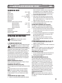
WARNING: some dust created by power sawing and other construction activities contains chemicals
known to the State of California to cause cancer and birth defects or other reproductive harm. Some
examples of these chemicals are:
Lead from lead-based paints,
Crystalline silica from bricks and cement and other masonry products, and
Arsenic and chromium from chemically-treated lumber
Your risk from these exposures varies, depending on how often you do this type of work. To reduce your
exposure to these chemicals:
Work in a well ventilated area,
Work with approved safety equipment, such as those dust masks that are specially designed to filter out
microscopic particles.
DVERTENCIA! El polvo creado al lijar, serruchar, pulir, taladrar o realizar otras actividades de la
construcción, contiene substancias químicas que se sabe producen cáncer, defectos de nacimiento u
otros daños al sistema reproductor. Algunos ejemplos de esos productos químicos son:
l El plomo de las pinturas a base de plomo
l la sílice cristalina de los ladrillos, del cemento y de otros productos de albañilería
l El arsénico y el cromo de la madera tratada químicamente
El riesgo que se corre a causa del contacto con esos productos varía según la frecuencia con que usted
realice este tipo de trabajos. Con el fin de reducir su exposición a esas substancias químicas:
l trabaje en un área bien ventilada
l utilice un equipo de seguridad adecuado, tal como una máscara contra el polvo especialmente diseñada
para filtrar partículas microscópicas.
AVERTISSEMENT: des produits chimiques connus de l’état de Californie pour causer des cancers et des
anomalies congénitales ou autre trouble reproductif. Voici des exemples de ces produits chimiques:
Plomb issu de peinture à base de plomb
Silice crystalline issue de briques et du ciment et autres produits de maçonnerie
Arsenic et chrome issus de bois traité chimiquement
Votre risque de ces expositions varie en fonction de la fréquence à laquelle vous effectuez ce travail. Pour
réduire votre exposition à ces produits chimiques:
Travaillez dans une zone bien ventilée;
Portez un équipement de sécurité approuvé, tel que des masques antipoussières spécialement conçus pour
éliminer les particules microscopiques par filtrage.
Visit us on the web at www.rockwelltools.com

RK7136.1
A
F G
H
I
J
K
L
A
N
N
B
O
Q
R
Blade/ Hoja /Lame
Inner flange/
Arandela Interior
/Rondelle
intérieure
Outer Flange/ Arandela
exterior/Rondelle extérieure
Bolt-left hand
thread/ Tornillo-
rosca izquierda/
Boulon de
serrage-filets
à gauche
S
P
20
21
22
24
25
26
27
28
29
1 2
111213
10
3
4
5
6
7
8
9
19
18
17
16
15
14
23
B
C
A1
A2
A3
A4
A5
A6
A7
A8
A9
A
D E
V
U
T
A
F G
H
I
J
K
L
A
N
N
B
O
Q
R
Blade/ Hoja /Lame
Inner flange/
Arandela Interior
/Rondelle
intérieure
Outer Flange/ Arandela
exterior/Rondelle extérieure
Bolt-left hand
thread/ Tornillo-
rosca izquierda/
Boulon de
serrage-filets
à gauche
S
P
20
21
22
24
25
26
27
28
29
1 2
111213
10
3
4
5
6
7
8
9
19
18
17
16
15
14
23
B
C
A1
A2
A3
A4
A5
A6
A7
A8
A9
A
D E
V
U
T

RK7136.1
A
F G
H
I
J
K
L
A
N
N
B
O
Q
R
Blade/ Hoja /Lame
Inner flange/
Arandela Interior
/Rondelle
intérieure
Outer Flange/ Arandela
exterior/Rondelle extérieure
Bolt-left hand
thread/ Tornillo-
rosca izquierda/
Boulon de
serrage-filets
à gauche
S
P
20
21
22
24
25
26
27
28
29
1 2
111213
10
3
4
5
6
7
8
9
19
18
17
16
15
14
23
B
C
A1
A2
A3
A4
A5
A6
A7
A8
A9
A
D E
V
U
T

Thank you for purchasing a ROCKWELL
®
power tool. We are confident that you will appreciate
the quality of the product and you will be entirely satisfied with your purchase. Please read
carefully the user safety and operating instructions on how to operate this product correctly
within safety norms and regulations.
Gracias por su compra de un producto ROCKWELL
®
. Estamos seguros de que apreciará
la calidad del producto y de que estará completamente satisfecho con su compra. Lea
cuidadosamente las instrucciones de seguridad y de operación para obtener mayor información
acerca de cómo utilizar éste producto correctamente dentro de las normas y reglas de
seguridad.
Merci d’avoir choisi un produit de marque ROCKWELL
®
. Nous sommes certains que ous
apprécierez la qualité de ce produit et qu’il saura vous satisfaire. Pour être renseigné sur toutes
les méthodes de travail correctes et sécuritaires répondant aux normes et règlements de
sécurité, veuillez lire attentivement la notice de sécurité et de fonctionnement présentée.

9
10˝ MITER SAW WITH INTEGRATED STAND ENG
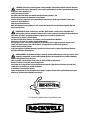
COMPONENT LIST
TRIGGER SWITCH
HANDLE
MOTOR HOUSING
SAW BLADE
RETRACTABLE SAFETY GUARD
FENCE
NO HAND ZONE
MITER TABLE
MITER DETENT LEVER
MITER LOCK HANDLE
KERF PLATE
MITER SCALE
MOUNTING HOLES (4)
VERTICAL CLAMP LOCKING SCREW
VERTICAL CLAMP
MITER ARM LOCK PIN
RETRACTABLE SAFETY GUARD ACTUATOR
SAFETY GUARD MOUNTING PLATE
UPPER BLADE GUARD
SPINDLE LOCK BUTTON
DUST EXTRACTION PORT
BEVEL LOCK KNOB
BEVEL SCALE
1
2
3
4
5
6
7
8
9
10
11
12
13
14
15
16
17
18
19
20
21
22
23

10˝ MITER SAW WITH INTEGRATED STAND ENG
10
ROLLER SUPPORT (2)
HOOK (4)
UPPER LEG (4)
LOWER LEG WITH FIXED FOOT (3)
LOWER LEG WITH ADJUSTABLE FOOT
LEG KNOB
* NOT ALL THE ACCESSORIES ILLUSTRATED OR DESCRIBED ARE INCLUDED IN STANDARD DELIVERY.
24
25
26
27
28
29
ACCESSORIES
Blade wrench 1
Work clamp 1
Miter lock handle 1
Dust bag 1
10˝x40 T carbide tipped saw blade 1
Roller supports 2
Hooks 4
Upper legs 4
Lower legs (3 with fixed foot, 1 with adjustable foot) 4
We recommend that you purchase your accessories
from the same store that sold you the tool. Use good
quality accessories with a well-known brand name.
Choose the type according to the work you intend to
undertake. Refer to the accessory packaging for further
details. Store personnel can assist you and offer advice.
READ ALL INSTRUCTIONS
BEFORE USING THIS APPLIANCE
INSTRUCTIONS PERTAINING TO A RISK OF INJURY
GENERAL
A.GROUNDING INSTRUCTIONS
All grounded, cord-connected tools:
In the event of a malfunction or breakdown,
grounding provides a path of least resistance for
electric current to reduce the risk of electric shock.
This tool is equipped with an electric cord having an
equipment-grounding conductor and a grounding
plug. The plug must be plugged into a matching
outlet that is properly installed and grounded in
accordance with all local codes and ordinances.
Do not modify the plug provided – if it will not fit the
outlet, have the proper outlet installed by a qualified
electrician.
Improper connection of the equipment-grounding
conductor can result in a risk of electric shock.
The conductor with insulation having an outer
surface that is green with or without yellow stripes
is the equipment-grounding conductor. If repair
or replacement of the electric cord or plug is
necessary, do not connect the equipment-grounding
conductor to a live terminal.
Check with a qualified electrician or service
personnel if the grounding instructions are not
completely understood, or if in doubt as to whether
the tool is properly grounded.
Use only 3-wire extension cords that have 3-prong
grounding plugs and 3-pole receptacles that accept
the tool’s plug.
Repair or replace damaged or worn cord immediately.
B.FOR ALL DOUBLE-INSULATED TOOLS
1. Replacement parts
When servicing use only identical replacement parts.
2. Polarized Plugs
To reduce the risk of electric shock, this equipment
has a polarized plug (one blade is wider than the
other). This plug will fit in a polarized outlet only
one way. If the plug does not fit fully in the outlet,

11
10˝ MITER SAW WITH INTEGRATED STAND ENG
reverse the plug. If it still does not fit, contact a
qualified electrician to install the proper outlet. Do
not change the plug in any way.
C. FOR ALL TOOLS AS APPLICABLE
1. KEEP GUARDS IN PLACE and in working order.
2. REMOVE ADJUSTING KEYS AND WRENCHES.
Form
habit of checking to see that keys and adjusting
wrenches are removed from tool before turning it
on.
3. KEEP WORK AREA CLEAN. Cluttered areas and
benches invite accidents.
4. DON’T USE IN DANGEROUS ENVIRONMENT. Don’t
use power tools in damp or wet locations, or expose
them to rain. Keep work area well lighted.
5. KEEP CHILDREN AWAY. All visitors should be kept
safe distance from work area.
6. MAKE WORKSHOP KID PROOF with padlocks,
master switches, or by removing starter keys.
7. DON’T FORCE TOOL. It will do the job better and
safer at the rate for which it was designed.
8. USE RIGHT TOOL. Don’t force tool or attachment to
do a job for which it was not designed.
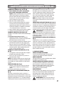
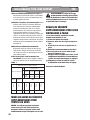
9. USE PROPER EXTENSION CORD. Make sure your
extension cord is in good condition. When using an
extension cord, be sure to use one heavy enough
to carry the current your product will draw. An
undersized cord will cause a drop in line voltage
resulting in loss of power and overheating. Table
1 shows the correct size to use depending on cord
length and nameplate ampere rating. If in doubt, use
the next heavier gage. The smaller the gage number,
the heavier the cord.
10. WEAR PROPER APPAREL. Do not wear loose
clothing, gloves, neckties, rings, bracelets, or other
jewelry which may get caught in moving parts.
Nonslip footwear is recommended. Wear protective
hair covering to contain long hair.
Exception: The reference to gloves may be omitted
from the instructions for a grinder.
11. ALWAYS USE SAFETY GLASSES. Also use face
or dust mask if cutting operation is dusty. Everyday
eyeglasses only have impact resistant lenses, they
are NOT safety glasses.
12. SECURE WORK. Use clamps or a vise to hold work
when practical. It’s safer than using your hand and it
frees both hands to operate tool.
13. DON’T OVERREACH. Keep proper footing and
balance at all times.
14. MAINTAIN TOOLS WITH CARE. Keep tools
sharp and clean for best and safest performance.
Follow instructions for lubricating and changing
accessories.
15. DISCONNECT TOOLS before servicing; when
changing accessories, such as blades, bits, cutters,
and the like.
16. REDUCE THE RISK OF UNINTENTIONAL
STARTING. Make sure switch is in off position
before plugging in.
17. USE RECOMMENDED ACCESSORIES. Consult the
owner’s manual for recommended accessories. The
use of improper accessories may cause risk of injury
to persons.
18. NEVER STAND ON TOOL. Serious injury could
occur if the tool is tipped or if the cutting tool is
unintentionally contacted.
19. CHECK DAMAGED PARTS. before further use
of the tool, a guard or other part that is damaged
should be carefully checked to determine that it will
operate properly and perform its intended function
– check for alignment of moving parts, binding of
moving parts, breakage of parts, mounting, and
any other conditions that may affect its operation.
A guard or other part that is damaged should be
properly repaired or replaced.
20. DIRECTION OF FEED. Feed work into a blade or
cutter against the direction of rotation of the blade
or cutter only.
21. NEVER LEAVE TOOL RUNNING UNATTENDED.
TURN POWER OFF. Don’t leave tool until it comes
to a complete stop.
Exception: The instructions for a bench grinder
need not contain the statement pertaining to leaving
the tool until it comes to a complete stop.

10˝ MITER SAW WITH INTEGRATED STAND ENG
12
Table 1
Minimum gage for cord
a
Ampere
Rating
Volts
Total length of cord in feet
120 V 25 ft. 50 ft. 100 ft. 150 ft.
More
Than
Not
More
Than
AWG
0
6
10
6
10
12
18
18
16
16
16
16
16
14
14
14
12
12
12 16 14 12
Not Recommended
a
Only the applicable parts of the table need to be included. For
instance, a 120-v product need not include the 240-V heading.
ADDITIONAL SAFETY WARNING
FOR ALL SAWS
DANGER: Coasting Cutting Tool Can Be Dangerous
– Apply brake immediately to stop cutting tool
when the switch is turned off.
WARNING: The torque developed during
braking may loosen the blade-retaining
nut, and the nut should be checked periodically
and tightened if necessary, especially after
braking.
ADDITIONAL SAFETY
INSTRUCTIONS FOR MITER SAW
1. For Your Own Safety Read Instruction Manual
Before Operating Miter Saw
a) Wear eye protection
b) Keep hands out of path of saw blade.
c) Do not operate saw without guards in place.
d) Do not perform any operation freehand.
e) Never reach around saw blade.
f) Turn off tool and wait for saw blade to
stop before moving workpiece or changing
settings.
g) Disconnect power (or unplug tool as
applicable) before changing blade or
servicing.
SAVE THESE INSTRUCTIONS
SYMBOLS
To reduce the risk of injury, user must read
instruction manual
Warning
Wear ear protection
Wear eye protection
Wear dust mask
Double insulation
n
o
No-load speed

13
10˝ MITER SAW WITH INTEGRATED STAND ENG
TECHNICAL DATA
Voltage 120 V~60 Hz
Rated current 14 A
No load speed 5200 rpm
Miter capacity 0º - 45º (left & right)
Bevel capacity 0º - 45º(left)
Blade diameter 10˝
Blade bore 5/8˝
Maximum cutting capacity (nominal)
Miter 0º/Bevel 0º 4˝x4˝, 2˝x6˝
Miter 0º/Bevel 45º 2˝x4˝, 1˝ x 6˝
Miter 45º/Bevel 0º 2˝x4˝
Miter 45º/Bevel 45º 2˝x4˝
Double insulation
Stand height 32˝
Maximum support length 10 ft
Machine weight 35.5 lbs
OPERATING INSTRUCTIONS
NOTE: Before using the tool, read the
instruction book carefully.
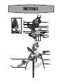
1. ASSEMBLING THE MITER SAW
The whole assembly process will take about 20 minutes.
WARNING: To prevent the accidental starting
that could cause possible serious personal
injury, ALWAYS assemble all parts to your saw BEFORE
connecting it to the power supply. The saw should
NEVER be connected to a power supply when you are
assembling parts, making adjustments, installing or
removing blades, or when not in use. Your compound
miter saw has been factory assembled and adjusted.
The miter lock handle and dust bag are the only parts
that have to be assembled to the saw. The leg stand
requires assembly.
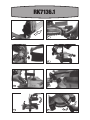
IDENTIFY THE PARTS (See Fig. A1)
Before assembly identify the parts as shown in Fig A1
and check for correct quantities.
ASSEMBLING THE LEGS (See Fig. A2,)
Insert the upper legs into the lower legs and press home
firmly.
Fit the leg assembly screw to each leg and tighten.
NOTE: For maximum rigidity, the upper and lower
legs have a locking taper. They are not intended to
be disassembled. The screw is fitted only for added
security.
FITTING THE LEGS (See Fig.A3, A4, A5)
a. Lock the saw head into lowered position using the
miter arm lock pin. Carefully lay the saw upside down
on the ground (it can lie in any position, After you
have fitted two legs, you will find it easy to just raise
the saw and fit the remaining legs with one hand).
b. Loosen the leg knob a few turns.
c. Slide corner of the leg inside the saw base corner
until the top of the leg locates behind the rib in the
base, and the knob locates “U” shaped notch in the
edge of the base. Fig A3 & A4
d. Tighten the knob and repeat for the other 3 legs.
e. Lift the saw upright onto it’s feet.
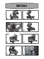
FITTING THE 2x4 SUPPORT (See Fig.A6, A7)
The support is standard 2x4 lumber supplied by the
customer. Recommended maximum length is 10 feet.
a. Place the 2x4 under the saw with one end resting on
the ground and raise the other end until it locates un
the cut-out of the base.
b. Fit a hook assembly to support the 2x4, locating the
wire ends through the holes in the saw base. DO
NOT TIGHTEN YET. Fig A6.
c. Lift the other end of the 2x4 and fit the second
hook assembly. Both hook assemblies can now be
tightened Fig A7.
FITTING THE ROLLER SUPPORTS (See Fig. A8, A9)
a. Fit the hook through the holes under the roller
support as shown in Fig A8.
b. Slide into place along the 2x4 and lock in the desired
position. Fig A9.
NOTE: Each roller support has a flip-up length stop (flip
stop). The roller supports should be installed with the
flip stop on the side away from the saw.
LOCK HANDLE (See Fig. A)
a. Place the threaded stud on the end of the miter lock
handle into the threaded hole in the control arm.
b. Turn clockwise to tighten.
DUST BAG INSTALLATION (See Fig. B)
To reduce build-up of sawdust and maintain top
efficiency of cutting, the saw may be connected to
a workshop vacuum cleaner via the dust outlet. The
outlet accepts a 1-1/4” inner diameter vacuum hose.
Alternatively saw dust collection can be achieved by
clipping a dust bag on the dust extraction port. A dust
bag is provided for use on your miter saw. To install
it, simply fit the dust bag over the exhaust port on the
upper blade guard. To empty the dust bag, remove
it from the dust exhaust port, open the dust bag by
unzipping the side fastener.
NOTE: To ensure optimal dust collection, empty the
dust bag when it becomes filled approximately 2/3 of
its capacity.

10˝ MITER SAW WITH INTEGRATED STAND ENG
14
WORK-PIECE CLAMP (See Fig. C, D)
The vertical clamp can be fitted on either side of the
saw and is fully adjustable to suit the size of the work-
piece. Do not operate the saw without clamping the
work-piece. Make sure that the clamp securing screws
are tightened.
WARNING: Use clamping position that does not
interfere with saw operation. Before switching
on, lower saw head to make sure clamp clears guard
and saw head assembly.
RELEASING THE SAW HEAD (See Fig. E)
When boxed, during storage, or transport the saw head
is locked in the down position. To release the head for
operation, apply downward pressure on the saw head
and pull the lock pin outwards and then turn pin 90º
to the left or right to lock it in place. The saw head can
now be raised and lowered.
2. KNOW YOUR SAW
BEVEL LOCK KNOB
The bevel lock knob (22) securely locks your compound
miter saw at the desired bevel angles.
MITER FENCE
Hold the work-piece securely against the miter fence (6)
when making all cuts.
SELF-RETRACTING LOWER BLADE GUARD
The lower blade guard (5) is made of shock-resistant,
see-through plastic and it provides protection from each
side of blade. It retracts over the upper blade guard as
the blade is lowered into the work-piece.
ELECTRIC BRAKE
This tool is equipped with an electric blade brake. If the
tool consistently fails to quickly stop blade after switch
trigger is released, have tool serviced by a qualified
person. The blade brake system is not a substitute for
the blade guard.
WARNING: Never use tool without a functioning
blade guard. Serious personal injury can result.
3. MITER LOCK HANDLE
The miter lock handle (10) securely locks your saw at
the desired miter angle.
4. SPINDLE LOCK BUTTON
The spindle lock button (20) on your saw allows you to
lock the spindle that keeps the blade in your saw from
rotating. Only depress and hold the lock button when
installing, changing or removing the blade.
5. TRIGGER SWITCH
To turn on the saw, squeeze the trigger switch (1).
Release switch to turn saw off.
6. POSITIVE STOPS ON THE Miter TABLE
The miter table has a miter scale that is color coded
for easy reading. It has miter indexes at 0º, 15º, 22.5º,
30º and 45º left and right with positive stops at 0º, 15º,
22.5º, 30º and 45º for exact miter cuts.
7. MOUNTING HOLES
When not used with the stand, your compound miter
saw should be permanently mounted to a firm, stable-
supporting surface, such as a workbench. Four bolt holes
have been provided in the saw base for this purpose.
Each of these four mounting holes should be securely
bolted using ¢15/32” machine bolts, lock washers and
hex nuts (not included). Bolts should be long enough to
fit through the saw base, lock washers, hex nuts and
the thickness of the workbench. Tighten all four bolts
securely. Carefully check the workbench after mounting
the saw to make sure that no movement can occur during
use. If any tipping, sliding or walking is noted, secure the
workbench to the floor before operating.
WARNING: Always make sure your compound
miter saw is securely mounted to a workbench
or an approved work-stand. Failure to do so could result
in an accident, resulting in possible serious personal
injury.
8. SQUARING THE SAW BLADE TO THE MITER SAW
(See Fig. L, M)
a. Unplug the saw.
b. Loosen (unscrew) the miter lock handle (10)
approximately one-half turn.
c. Depress the miter lock plate and rotate the miter
table until the pointer is at 0°.
d. Release the miter lock plate and securely tighten the
miter lock handle.
e. Loosen the bevel lock handle.
f. Rotate the bevel rotating housing so the pointer is at
0°. Lock bevel lock handle.
g. Pull the saw arm “down” and engage the lock pin.
Saw arm should now be in the transport or storing
position.
h. Now place a combination square on the miter table
and against the flat part of the saw blade.
NOTE: Be sure that the square contacts the flat side of
the blade, not the carbide teeth. This can be easily done
by easing the saw arm down with the blade in the throat
plate until the carbide teeth are below the table.

15
10˝ MITER SAW WITH INTEGRATED STAND ENG
i. Rotate the blade by hand and check the Blade-to-
Table squareness at several points. If the square is
not flat up against the blade when squared to the
table, perform steps j through l.
j. First locate the stop bolt and positive stop
adjustment screw for 0° angles. It is located on the
right side of the bevel rotating housing sleeve.
k. Loosen the bevel lock handle, and then rotate the
saw blade arm to the left so it clears the positive
stop adjustment screw.
l. Adjust the positive stop adjustment screw up or
down to bring the saw blade into alignment with the
combination square.
NOTE: Make only slight adjustment to the screw,
Then rotate the saw arm back to 0°. Check blade with
square. Repeat this process until the blade is squared
to the table.
m. After you have the blade squared to the table, tighten
the lock nut that holds the positive stop adjustment
screw.
n. Rotate the saw blade arm back to 0° on the bevel
scale, then tighten the bevel lock handle. Repeat
steps j through l for 45° stop (see Fig. N).
THROAT PLATE SLOT
For your convenience the slot in the zero clearance
throat plate has been pre-cut at the factory to allow
complete blade clearance at any angle between 0°and
45°.
PIVOT ADJUSTMENTS
NOTE: These adjustments were made at the factory
and under normal circumstances do not require
readjustment.
TRAVEL PIVOT ADJUSTMENT
Your saw arm should rise completely to the up position
by itself. To avoid risk of personal injury, if your saw
arm does not rise by itself or if there is play in the pivot
joints, have your saw serviced by qualified person.
BEVEL PIVOT ADJUSTMENT
Your compound miter saw arm should bevel easily by
loosening the bevel lock knob (22) and tilting the saw
arm to the left.
9. TO REPLACE SAW BLADE (See Fig .O-S)
WARNING: A 10" blade is the maximum blade
capacity of your saw. A larger than 10” blade
will come in contact with the blade guards. Also, never
use a blade that is so thick that it prevents the outer
blade washer from engaging with the flat side of the
spindle. Blades that are too large or too thick can result
in an accident causing serious personal injury.
a. Unplug the saw.
WARNING:To prevent personal injury, always
disconnect the plug from power source before
assembling parts, making adjustments or changing blades.
b. Push down on saw arm and pull out the lock pin to
release saw arm.
c. Raise saw arm to its full raised position. Be cautious
because saw arm is spring loaded.
d. Loosen two phillips screw on the blade bolt cover,
see Fig O and Fig P.
e.
Gently raise the lower blade guard bracket to release
the lower blade guard from the notch. This will allow
the lower blade guard and the blade bolt cover to be
rotated up and back to expose the blade bolt, see Fig Q.
f. Rotate the lower blade guard and the blade bolt
cover up and back to expose the blade bolt.
g. Press the spindle lock button and rotate the blade
bolt until the spindle locks.
h. Use the blade wrench (included) to loosen and
remove the blade bolt. Turn the blade bolt clockwise
to loosen. DO NOT remove the inner blade washer.
i. Wipe a drop of oil onto the inner blade washer and
the outer blade washer where they come in contact
with the blade.
WARNING: If the inner blade washer has been
removed, replace it BEFORE placing blade on
the spindle. Failure to do so could cause an accident
because the blade will not tighten properly.
j. Fit the saw blade inside the lower blade guard and
onto the inner blade washer. The blade teeth should
point downward at the front of the saw.
CAUTION: ALWAYS install the blade with the blade teeth
and the arrow printed on the side of the blade pointing
down at the front of the saw. The direction of blade
rotation is also stamped with an arrow on the upper
blade guard.
k. Replace the outer blade washer.
The Double “D” flats on the blade washers align with
the flats on the spindle.
l. Press the spindle lock button and replace blade bolt.
m. Tighten the blade bolt securely by turning it counter-
clockwise with the blade wrench.
n. Replace the lower blade guard and the blade bolt
cover.
o. Securely re-tighten the Phillips screw that secures
the blade bolt cover.
WARNING: To prevent damage to the spindle
lock, always allow the motor to come to
a complete stop before engaging the spindle lock.
Always make sure the spindle lock is disengaged

10˝ MITER SAW WITH INTEGRATED STAND ENG
16
before reconnecting saw to the power source. Your
compound miter saw has been adjusted at the factory
for making very accurate cuts. However, some of the
components may have been jarred out of alignment
during shipping. Also over a period of time, some
readjustment will probably become necessary due to
wear. After unpacking your saw, check the adjustments
BEFORE using your saw. Make any adjustments that are
necessary and periodically check the parts alignment
to be sure that your saw is cutting accurately. Your saw
should never be connected to a power source when you
are assembling parts, making adjustments, installing or
removing blades, or when not in use. Disconnecting your
saw will prevent accidental starting that could cause
serious injury.
10. CUTTING WITH YOUR COMPOUND MITER SAW
Only use your compound miter saw for the purposes
listed below:
-Crosscutting wood and plastic
-Crosscutting miters, joints, etc., for picture frames,
moldings, door casings, and fine joinery
NOTE: The blade included with this saw is ideal for a
wide variety of wood cutting operations.
WARNING: Before starting any cutting
operation, clamp or bolt your compound miter
saw to the leg stand, or a work bench. Never operate
your miter saw on the floor or in a crouched position.
Failure to heed this warning could result in serious
personal injury.
WARNING: When using a hold-down clamp to
secure the work-piece, clamp work-piece on
one side of the blade only. The work-piece MUST remain
free on one side of the blade to prevent the blade from
binding in the work-piece. The work-piece binding the
blade will cause the motor to stall and cause kickback,
resulting in possible serious personal injury.
CROSS CUTTING (See Fig F,G,H)
A crosscut is a cut made across the grain of the
workpiece. A straight crosscut is a cut made with the
miter table set in the 0º position. Miter crosscuts are
made with the miter table set at some angle other than
zero.
TO CROSSCUT WITH YOUR MITER SAW:
a. Unplug the saw.
WARNING: To prevent personal injury, always
disconnect the plug from power source before
assembling parts, making adjustments or changing blades.
b. Pull out the lock pin and lift the saw arm to
its full height.
c. Loosen (unscrew) the Miter Lock Handle
approximately one-half turn.
d. Press miter lock plate down with your thumb and
hold.
e. Rotate the control arm until the pointer aligns with
the desired angle on the miter scale.
f. Release the miter lock plate.
NOTE: You can quickly locate 0°, 15°, 22.5°, 30° left or
right, and 45º left or right by releasing the lock plate as
you rotate the control arm. The lock plate will seat itself
in one of the positive stop notches, located in the miter
table frame.
g. Tighten the miter lock handle securely.
WARNING: To avoid serious personal injury,
ALWAYS tighten the miter lock handle securely
BEFORE making a cut. Failure to do so could result
in movement of the control arm or miter table while
making a cut.
h. Place work-piece flat on the miter table with one
edge securely against the fence. If the board is
warped, place the convex side against the fence. If
the concave edge of the board is against the fence,
the board could collapse on the blade at the end of
the cut and jam the blade.
i. When cutting long pieces of lumber or molding,
support the opposite end of the stock with a roller
stand or with another work surface that is level with
the saw table.
j. Align cutting line on the work-piece with the edge on
the saw blade.
k. Hold the stock firmly with one hand and secure
it against the fence. Use the hold-down clamp to
secure the work-piece when possible.
WARNING: To avoid serious personal injury,
ALWAYS keep your hands outside the “no hands
zone”(red lines); at least 6” from blade. Also, NEVER
perform any cutting operation “freehand” (i.e. without
holding work-piece against the fence); the blade could
grab the work-piece, causing it to slip and twist.
l. BEFORE turning on the saw, perform a dry run of the
cutting operation just to make sure that no problems
will occur when the cut is made.
m. Hold the saw handle firmly, when squeezing the
trigger switch. Allow several seconds for the blade to
reach maximum speed.
n. Slowly lower the blade into and through the
workpiece.
o. Release the trigger switch and allow the saw blade
to stop rotating BEFORE raising the blade out of the
work-piece. Wait until the electric brake stops the

17
10˝ MITER SAW WITH INTEGRATED STAND ENG
blade from turning BEFORE removing the work-piece
from the miter table.
11. BEVEL CUTTING (See Fig. I, J,K)
A bevel cut is a cut made across the grain of the
workpiece with the blade at an angle to the work-piece.
A straight bevel cut is made with the miter table set in
the 0º position and the blade set at an angle between 0º
and 45º.
TO BEVEL CUT WITH YOUR MITER SAW
a. Unplug the saw.
WARNING:To prevent personal injury, ALWAYS
disconnect the plug from power source BEFORE
assembling parts, making adjustments or changing blades.
b. Pull out the lock pin and lift the saw arm to its full
height.
c. Loosen the miter lock handle. Rotate the miter lock
handle approximately one-half turn to the left to
loosen.
d. Press down on miter lock plate to disengage.
e. Rotate the control arm until the pointer aligns with
zero on the miter scale.
f. Release the miter lock plate.
g. Tighten the miter lock handle securely.
NOTE: You can quickly locate 0° by releasing the lock
plate as you rotate the control arm. The lock plate will
seat itself in one of the positive stop notches, located in
the miter table frame.
WARNING: To avoid serious personal injury,
ALWAYS tighten the miter lock handle securely
BEFORE making a cut. Failure to do so could result
in movement of the control arm or miter table while
making a cut.
h. Loosen the bevel lock knob (22) and move the saw
arm to the left to the desired bevel angle. Bevel
angles can be set from 0°to 45°. The 45° triangle
on the miter fence (6) provides for the maximum
clearance required for adjusting the miter saw angle
when making a bevel or compound cut.
i. Align the indicator point with the desired angle.
j. Once the saw arm has been set at the desired angle,
securely tighten the bevel lock knob.
k. Place work-piece flat on the miter table with one
edge securely against the fence. If the board is
warped, place the convex side against the fence. If
the concave edge of the board is against the fence,
the board could collapse on the blade at the end of
the cut and jam the blade.
l. When cutting long pieces of lumber or molding,
support the work-piece with a roller stand or other
support to bring the work-piece level with the saw
table.
m. Align cutting line on the work-piece with the edge on
the saw blade.
n. Hold the stock firmly with one hand and secure
it against the fence. Use the hold-down clamp to
secure the work-piece when possible.
WARNING: To avoid serious personal injury,
ALWAYS keep your hands outside the “no hands
zone”(red lines); at least 6” from blade. Also, NEVER
perform any cutting operation “freehand” (i.e. without
holding work-piece against the fence); the blade could
grab the work-piece, causing it to slip and twist.
o. MAKE SURE that there will be no obstructions to
interfere with making the cut.
p. Hold the saw handle firmly when squeezing the
trigger switch. Allow several seconds for the blade to
reach maximum speed.
q.
Slowly lower the blade into and through the workpiece.
r. Release the trigger switch and allow the saw blade
to stop rotating BEFORE raising the blade out of the
work-piece. Wait until the electric brake stops the
blade from turning BEFORE removing the work-piece
from the miter table.
12. COMPOUND MITER CUTTING
A compound miter cut is a cut made using a miter angle
and a bevel angle at the same time. This type of cut is
used for moldings, picture frames, and boxes
with sloping sides. To make this type of cut the control
arm on the miter table must be rotated to the correct
angle and the saw arm must be tilted to the correct
bevel angle.
ALWAYS take special care when making compound
miter setups due to the interaction of the two angle
settings.
Adjustments of miter and bevel settings are dependent
on one another. Each time you adjust the miter setting,
you change the effect of the bevel setting. Also, each
time you adjust the bevel setting, you change the effect
of the miter setting. It may take several settings to
obtain the desired cut. The first angle setting should be
checked after setting the second angle, since adjusting
the second angle affects the first. Once the two correct
settings for a particular cut have been obtained,
ALWAYS make a test cut in scrap material BEFORE
making a finish cut in good material.

10˝ MITER SAW WITH INTEGRATED STAND ENG
18
TO MAKE A COMPOUND MITER CUT WITH YOUR
MITER SAW (See Fig K)
a. Unplug the saw.
WARNING: To prevent personal injury, ALWAYS
disconnect the plug from power source BEFORE
assembling parts, making adjustments or changing
blades.
b. Pull out the lock pin (16) and lift the saw arm to its
full height.
c. Loosen the miter lock handle (10). Rotate the miter
lock handle approximately one-half turn to the left to
loosen.
d. Lift miter lock plate (9) to disengage.
e. Rotate the control arm until the pointer aligns with
the desired angle on the miter scale.
f. Release the miter lock plate.
NOTE: You can quickly locate 0°, 15°, 22.5°, 30° and
45° left or right by releasing the miter lock plate as you
rotate the control arm. The miter lock plate will seat
itself in one of the positive stop notches, located in the
miter table frame.
g. Tighten the miter lock handle securely.
WARNING: To avoid serious personal injury,
ALWAYS tighten the miter lock handle securely
BEFORE making a cut. Failure to do so could result in
movement of the control arm or miter table while making
a cut. The 45° triangle on the miter fence provides for
the maximum clearance required for adjusting the miter
saw angle when making a bevel or compound cut.
h. Loosen the bevel lock knob (22) and move the saw
arm to the left to the desired bevel angle. Bevel
angles can be set from 0° to 45°.
i. Align the indicator point with the desired angle.
j. Once the saw arm has been set at the desired angle,
securely tighten the bevel lock knob.
k. Bevel angles can be set from 0° to 45°.
l. Place work-piece flat on the miter table with one
edge securely against the fence. If the board is
warped, place the convex side against the fence. If
the concave edge of the board is against the fence,
the board could collapse on the blade at the end of
the cut and jam the blade.
m. When cutting long pieces of lumber or molding,
support the work-piece with a roller stand or other
support to bring the work-piece level with the saw
table.
n. Align cutting line on the work-piece with the edge on
the saw blade.
o. Hold the stock firmly with one hand and secure
it against the fence. Use the hold-down clamp to
secure the work-piece when possible.
WARNING: To avoid serious personal injury,
ALWAYS keep your hands outside the “no hands
zone”(red lines); at least 6” (150mm) from blade. Also,
NEVER perform any cutting operation “freehand” (i.e.
without holding work-piece against the fence); the blade
could grab the work-piece, causing it to slip and twist.
p. MAKE SURE that there will be no obstructions to
interfere with making the cut.
q. Hold the saw handle firmly, when squeezing the
trigger switch. Allow several seconds for the blade to
reach maximum speed.
r. Slowly lower the blade into and through the
workpiece.
s. Release the trigger switch and allow the saw blade
to stop rotating BEFORE raising the blade out of the
work-piece. Wait until the electric brake stops the
blade from turning BEFORE removing the work-piece
from the miter table.
13. SUPPORT LONG WORK-PIECES
Long work-pieces require extra supports. The supports
should be placed along the work-piece so it does not
sag. The support should allow the workpiece to lay flat
on the base of the saw and work-table during the cutting
operation. Use the work clamp to secure the work-piece.
WARNING: To avoid serious personal injury,
ALWAYS keep your hands outside the “no hands
zone”(red lines); at least 6” from blade. Also, NEVER
perform any cutting operation “freehand” (i.e. without
holding work-piece against the fence); the blade could
grab the work-piece, causing it to slip and twist.
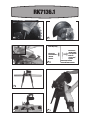
14. USING THE MITER SAW WITH LEGS AND ROLLER
SUPPORTS(See Fig .T)
Always consider the stability of the work both before
and after the cut (after the cut a previously balanced
workpiece can tip to one side).
Maximum recommended length for the 2x4 support is
10 feet for normal work.
For longer work pieces or for heavy work, additional
support is required.
15. USING THE FLIP STOPS (See Fig.U)
For repeated cutting of work the same length, the flip
stops save a lot of time.
Raise the flip stop to the operating position, then move
the roller assembly until the desired length is set.
To set the length:
a. Measure and cut a first sample work piece to the

19
10˝ MITER SAW WITH INTEGRATED STAND ENG
correct length.
b. Lower the saw and lock down.
c. Slide the sample work piece into position until it
touches the blade.
d. Loosen and slide the roller support until the flip stop
touches the other end of the sample workpiece, re-
tighten.
16. USING THE ROLLER SUPPORTS WITHOUT LEGS
(Fig V).
The roller supports can be used even when the legs are
not being used.
Simply place the rollers on the same table top as the
miter saw, their height is matched to the saw.
The roller supports also have holes allowing for
temporary screw fixing as shown in Fig V.
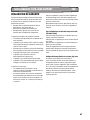
WORKING HINTS FOR YOUR
COMPOUND MITER SAW
1. CUTTING WARPED MATERIAL
When cutting warped material, always make sure that
it is positioned on the miter table with the convex side
against the fence. If the warped material is positioned
the wrong way, it will pinch the blade near the end of
the cut.
CAUTION:
To avoid kickback and to avoid
serious personal injury, NEVER position the
concave edge of a bowed or warped material against
the fence.
CLAMPING WIDE WORK-PIECE
When cutting wide work-pieces, the boards should
always be clamped with a hold-down clamp.
MAINTAIN TOOLS WITH CARE
Keep tools sharp and clean for better and safer
performance. Follow instructions for lubricating and
changing accessories. Inspect tool cords periodically
and if damaged, have repaired by authorized service
facility.
Your power tool requires no additional lubrication or
maintenance. There are no user serviceable parts in
your power tool. Never use water or chemical cleaners
to clean your power tool. Wipe clean with a dry cloth.
Always store your power tool in a dry place. Keep the
motor ventilation slots clean. Keep all working controls
free of dust. If you see some sparks flashing in the
ventilation slots, this is normal and will not damage your
power tool.

10˝ MITER SAW WITH INTEGRATED STAND ENG
20
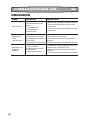
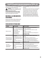
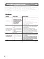
TROUBLESHOOTING
Problem Probable cause Suggested remedy
motor will not run
1. Switch in OFF position
2. No electrical power at wall
outlet
3. switch broke down
4. motor broke down
5. defective cable
1. Make sure saw is plugged in and switch is pressed
2. Check circuit breaker or fuse at electrical panel.
3. replace switch
4. contact service center for Replacing motor assembly.
5. replace cable
Motor hums but
cannot
run or runs slowly
1.Low voltage
2.Loose electrical connections
3.Wrong gauge wire or length of
extension cord
4.Shorted or open motor winding
1. Check voltage at wall outlet with voltmeter.
2. Check all electrical connections.
3. Check extension cord chart for proper extension
cord usage.
4. contact service center for Replacing motor assembly.
Flow blows/circuit
breaker trips
repeatedly
1. circuit overloaded
2. Wrong gauge wire or length
of extension cord
3. Motor shorted or seized
1. Disconnect other electrical appliances from circuit
or operate saw on its own branch circuit.
2. Check extension cord chart for proper extension
cord usage.
3. contact service center for Replacing motor assembly.
La page est en cours de chargement...
La page est en cours de chargement...
La page est en cours de chargement...
La page est en cours de chargement...
La page est en cours de chargement...
La page est en cours de chargement...
La page est en cours de chargement...
La page est en cours de chargement...
La page est en cours de chargement...
La page est en cours de chargement...
La page est en cours de chargement...
La page est en cours de chargement...
La page est en cours de chargement...
La page est en cours de chargement...
La page est en cours de chargement...
La page est en cours de chargement...
La page est en cours de chargement...
La page est en cours de chargement...
La page est en cours de chargement...
La page est en cours de chargement...
La page est en cours de chargement...
La page est en cours de chargement...
La page est en cours de chargement...
La page est en cours de chargement...
La page est en cours de chargement...
La page est en cours de chargement...
La page est en cours de chargement...
La page est en cours de chargement...
-
 1
1
-
 2
2
-
 3
3
-
 4
4
-
 5
5
-
 6
6
-
 7
7
-
 8
8
-
 9
9
-
 10
10
-
 11
11
-
 12
12
-
 13
13
-
 14
14
-
 15
15
-
 16
16
-
 17
17
-
 18
18
-
 19
19
-
 20
20
-
 21
21
-
 22
22
-
 23
23
-
 24
24
-
 25
25
-
 26
26
-
 27
27
-
 28
28
-
 29
29
-
 30
30
-
 31
31
-
 32
32
-
 33
33
-
 34
34
-
 35
35
-
 36
36
-
 37
37
-
 38
38
-
 39
39
-
 40
40
-
 41
41
-
 42
42
-
 43
43
-
 44
44
-
 45
45
-
 46
46
-
 47
47
-
 48
48


Rockwell ShopSeries RK 713 6.1 Instructions Manual
- Catégorie
- Scies à onglet
- Taper
- Instructions Manual
dans d''autres langues
- English: Rockwell ShopSeries RK 713 6.1
- español: Rockwell ShopSeries RK 713 6.1
Documents connexes
-
Rockwell RK7323 Mode d'emploi
-
-
Rockwell RK9033 Manuel utilisateur
-
-
 Positec USA JawStand XP Portable Work Support Stand Manuel utilisateur
-
 Positec USA RK9034 Manuel utilisateur
-
-


Autres documents
-
RIDGID R4210 Manuel utilisateur
-
-
-
-
-
-
Ryobi TSS120L Mode d'emploi
-
-
-
 Shopmaster S26-262L Mode d'emploi
