Maytag MDG25PD Installation Instructions Manual
- Catégorie
- Sèche-linge électriques
- Taper
- Installation Instructions Manual
Ce manuel convient également à

COMMERCIAL HE DRYER iNSTALLATiON iNSTRUCTiONS
(original instructions)
Gas
iNSTRUCTiONSD'INSTALLATIOND'UN SECHE-LINGEHECOMMERCIAL
(traduction des instructionsd'origine)
A gaz
INSTRUCCIONES DE INSTALACION- SECADORA HE COMERCIAL
(traducci6n de las instruccionesoriginales)
A gas
ISTRUZIONID'INSTALLAZIONE- ASCIUGATRICEHE COMMERCIALE
(traduzione delie istruzionioriginali)
A gas
MDG25PN MDG25PD
W10379555A
www.maytagcommerciaNaundry.com

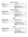
TABLEOF CONTENTS
DRYER SAFETY ............................................................................ 3
DRYER DISPOSAL ........................................................................ 4
INSTALLATION REQUIREMENTS .............................................. 4
Tools and Parts .......................................................................... 4
Location Requirements .............................................................. 4
Electrical Requirements - Gas Dryer .......................................... 5
Gas Supply Requirements ........................................................ 6
Venting Requirements ................................................................ 7
INSTALLATION INSTRUCTIONS - GAS DRYER .................... 9
Install Leveling Legs.................................................................... 9
Make Gas Connection ................................................................ 9
Connect Vent .............................................................................. 9
Complete Installation ................................................................ 9
MAINTENANCE INSTRUCTIONS .......................................... 10
TECHNICAL SPECIFICATIONS - GAS DRYER ...................... 10
REVERSING THE DOOR SWING (OPTIONAL) ....................... 11
ELECTRONIC CONTROL SETUP .......................................... 13
WARRANTY .............................................................................. 17
TABLEDESMATIERES
SECURITE DU SECHE-LINGE ................................................ 18
ELIMINATION DU SECHE-LINGE .......................................... 19
EXIGENCES D'INSTALLATION ................................................ 19
Outil{age et pi_ces .................................................................... 19
E×igences d'emptacement ...................................................... 20
Specifications electriques - seche-tinge h gaz ....................... 21
Specifications de I'alimentation en gaz .................................. 22
Exigences concemant revacuation .......................................... 23
INSTRUCTIONS D'INSTALLATION -
SECHE-LINGE A GAZ .............................................................. 25
Installation des pieds de nivellement ........................................ 25
Raccordement h {a canalisation de gaz .................................. 25
Raccordement du conduit d'evacuation ................................ 25
Achever I'instattation ................................................................ 25
INSTRUCTIONS D'ENTRETIEN ............................................... 26
FICHE TECHNIQUE - SECHE-L{NGE A GAZ ........................ 26
INVERSION DU SENS D'OUVERTURE DE LA PORTE ......... 27
REGLAGE DE LA CARTE
DE C{RCUITS ELECTRONIQUES .......................................... 29
GARANTIE ................................................................................ 33
P
INDICE
SEGUR}DAD DE LA SECADORA ............................................ 34
EL{MINAClON DE LA SECADORA .......................................... 35
REQUIS{TOS DE INSTALAClON ............................................ 35
Piezas y herramientas .......................................................... 35
Requisitos de ubicaci6n ........................................................ 35
Requisitos electricos - secadora a gas ................................ 36
Requisitos del suministro de gas ............................................ 37
Requisitos de ventilaci6n .................................................... 38
INSTRUCCIONES DE INSTALACION -
SECADORA A GAS ................................................................ 40
InstataciSn de las paras niveladoras .................................... 40
Conexi6n del suministro de gas ............................................ 40
Conexi6n del ducto de escape ............................................ 40
Complete la instalaci6n ........................................................ 40
INSTRUCCIONES DE MANTENIM{ENTO .............................. 41
ESPEClFICACIONES TI_CNICAS - SECADORA A GAS ......41
COMO INVERTIR EL SENTIDO DE APERTURA
DE LA PUERTA ....................................................................... 42
PROGRAMACION DEL CONTROL ELECTRONICO ............ 44
GARANTiA ................................................................................ 48
INDICE
SICUREZZA DELL'ASCIUGATRICE ........................................ 49
L'ELIMINAZIONE DELUASCIUGATRICE .................................. 50
REQUISITI D'INSTALLAZIONE ................................................ 50
Attrezzi e componenti .............................................................. 50
Requisiti di ubicazione ............................................................ 50
Requisiti elettrici - asciugatrice a gas .................................... 51
Requisiti di alimentazione det gas ............................................ 52
Requisiti di scarico ................................................................ 53
ISTRUZIONi DI INSTALLAZIONE- ASCIUGATRICE
A GAS ...................................................................................... 55
Installazione dei piedin{ di regolazione .................................... 55
Eseguire il colleganento gas .................................................... 55
Connessione delto scarico ...................................................... 55
Comptetamento dell'instatlazione ............................................ 56
ISTRUZIONI DI MANUTENZIONE ......................................... 57
DATI TECNICI - ASCIUGATRICE A GAS .............................. 57
INVERS{ONE DELLA ROTAZ{ONE D} APERTURA ............... 58
CONFIGURAZIONE DEI CONTROLLI ELETTRONICI .......... 60
GARANZIA .................................................................................. 64

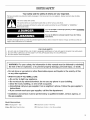
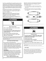
DRYERSAFETY
Your safety and the safety of others are very important.
We have provided many important safety messages in this manual and on your appliance. Always read and obey all safety
messages.
This is the safety alert symbol.
This symbol alerts you to potential hazards that can kill or hurt you and others.
All safety messages will follow the safety alert symbol and either the word "DANGER" or "WARNING."
These words mean:
You can be killed or seriously injured if you don't immediately
follow instructions.
You can be killed or seriously injured if you don't follow
instructions.
All safety messages will tell you what the potential hazard is, tell you how to reduce the chance of injury, and tell you what can
happen if the instructions are not followed.
FOR YOUR SAFETY
1. DO NOT USE OR STORE PETROL OR OTHER FLAMMABLE MATERIALS IN THIS APPLIANCE OR NEAR THIS APPLIANCE.
2. DO NOT SPRAY AEROSOLS IN THE VICINITY OF THIS APPLIANCE WHILE IT IS IN OPERATION.
3. DO NOT MODIFY THIS APPLIANCE.
WARNING: For your safety, the information in this manual must be followed to minimize
the risk of fire or explosion, or to prevent property damage, personal injury, or death.
- Do not store or use petrol or other flammable vapors and liquids in the vicinity of this
or any other appliance.
-WHAT TO DO {F YOU SMELL GAS:
® Do not try to light any appliance.
® Do not touch any electrical switch; do not use any phone in your building.
® Clear the room, building, or area of all occupants.
® Immediately call your gas supplier from a neighbor's phone. Follow the gas supplier's
instructions.
® if you cannot reach your gas supplier, call the fire department.
- {nstallation and service must be performed by a qualified installer, service agency, or
the gas supplier.
Model Nomenc{ature
MDG Maytag Dryer- Gas
##(e.g. 25) Model Type Number
PN Electronic Control - Non-Pay
PD Electronic Control - Coin Drop enabled
3

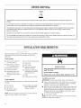
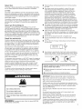
DRYERDISPOSAL
This appliance is marked according to the European directive 2002/96/EC on Waste Electrical and Electronic Equipment
(WEEE).
By ensuring this product is disposed of correctly, you will help avoid potential negative consequences for the environment and
human health, which could otherwise be caused by inappropriate waste handling of this product.
The symbol on the product, or on the documents accompanying the product, indicates that this appliance may not be treated
as household waste. Instead it shah be handed over to the applicable collection point for the recycling of electrica{ and
electronic equipment.
Disposal must be carried out in accordance with local environmental regulations for waste disposal.
For more detailed information about treatment, recovery and recycling of this product, please contact your local city office, your
household waste disposal service or the shop where you purchased the product.
INSTALLATIONREQUIREMENTS
Gather the required tools and parts before starting installation.
Read and follow the instructions provided with any tools
listed here.
Tools needed:
m 200 mm (8") or 250 mm [] 8 mm (5/16") socket wrench
(10") Pipe wrench [] Utility knife
[] 200 mm (8") or 250 mm [] Vent clamps
(10") Adjustable wrench
[] Pipe-joint compound
[] Flat-blade screwdriver resistant to LP gas
[] Phillips screwdriver [] Sealing gun and sealing
[] Adjustable wrench that compound (for installing
opens to 25 mm (1") or new exhaust vent)
hex-head socket wrench [] Pliers
[] Level [] Stiff-bladed putty knife
Parts supplied:
Remove parts bag from dryer drum. Check that all parts were
included.
[] Foot boot (4)
[] Dryer foot (4)
[] PD models: Cam for
service door lock
[] PN models: Card reader
bezel, card reader wire
harness, hardware
NOTE: The circuit diagram for this dryer is located inside the
lower front panel, within the Tech Sheets.
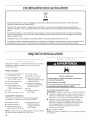
Explosion Hazard
Keep flammable materials and vapors, such as petrol,
away from dryer.
Do not install in a garage.
Failure to do so can result in death, explosion, or fire.
If installing a gas dryer:
IMPORTANT: Observe all governing codes and ordinances.
[] Check code requirements: Some codes limit or do not permit
installation of clothes dryers in garages, closets, or sleeping
quarters. Contact your local building inspector.
[] Make sure that lower edges of the cabinet, plus the back and
bottom sides of the dryer, are free of obstructions to permit
adequate clearance of air openings for combustion air. See
"Recessed Area and Closet Installation Instructions" below
for minimum spacing requirements.
[] Do not install on carpet.
NOTE: The dryer must not be installed in an area where it will be
exposed to water and/or weather.

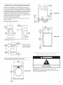
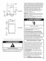
Recessed Area and Closet Installation instructions
This dryer may be installed in a recessed area or closet. This
dryer must not be installed behind a lockable door, a sliding door,
or a door with a hinge on the opposite side to that of the dryer.
The installation spacing is in millimeters and is the minimum allowable.
Additional spacing should be considered for ease of installation,
servicing, and compliance with local codes and ordinances.
If installed in a closet with a door, the minimum unobstructed air
opening in the top and bottom is required. Louvered doors with
equivalent air openings are acceptable.
The dryer must be exhausted outdoors.
No other fuel-burning appliance may be installed in the same
closet as the dryer.
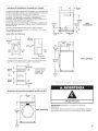
Minimum Installation Clearances
o o
381 mm
(,5,,Ir]
r-m[::::_-.
Omm
10")
Recessed front view
Omm
(0")
356 mm
(14") max
Closet
door
c_
,.... ]
.............. 0 mm
(0")
_1 1-25 mm(1")
Closet side view
Additional clearances may be required for wall, door, and floor moldings, or if
external exhaust elbow is used.
L
76 mm (3")
*Opening is the minimum
for a closet door. Louvered
doors with equivalent air
openings are acceptable.
(48in_)
Front closet
view 0 door
(24 in_)
76 mm (3")
:::::::::::::::::::::::::::: r r r r
Product Dimensions 686 mm (27") dryer
965 mm
686 mm
(27")
i===_
I !
I I
{ !
I {
I II m I
FRONT VIEW
32 mm-_
(11/4")
==q c_"
{
f
ELECTRI
-_- b358 rnm_-
(14")
715 mm
?!
BACK VIEW
203 mm
(8")
921 mm
(36i/4")
25 mm
(1")
736 mm
, (29) 695 mm
_l(_
! !
! !
SIDE VIEW
Dangerous Voltage
Important: Observe all governing codes and ordinances.
You will need an earthed electrical outlet located within 610 mm
(2 feet) of either side of the dryer.
÷
25 mm
(1")
5

This dryer is supplied/fitted with an electricity supply cord and
plug. It should be connected to electricity supply socket at the
voltage shown on the rating plate. The minimum supply fuse
capacity should be 5A. The dryer must be positioned so that the
plug is clearly visible and accessible. This plug also provides the
function of an emergency stop control for the user. Ifthe fitted
plug is not used, the electrical connection must be carried out
by a competent electrician in accordance with local or national
codes.
If the supply cord is damaged, it must be replaced with a
specially terminated cord by an authorized service agent or
a similarly competent person in order to avoid a hazard.
Do not use an adapter.
Do not use an extension cord.
NOTE: In accordance with the European EMC Directive
(2004/108/EC), the maximum electricity supply system
impedance to which the gas dryer should be connected
is declared to be 0.054 Ohm + j0.034 Ohm.
NOTE: Electrical safety standards: The manufacturer has
chosen compliance with IEC/EN.60335 standards as the most
appropriate for this product.
Electric Shock Hazard
This is a 3=wire appliance which must be earthed.
Do not earth to a gas pipe.
Do not change the power supply cord plug. If it does
not fit the outlet, have a proper outlet installed by a
qualified electrician.
Do not use an extension cord with this dryer.
Failure to follow these instructions could result in
death, fire, or serious injury.
If codes permit and an additional earth bond wire is used, it is
recommended that a qualified electrician determine that the earth
bond path is adequate.
EARTHING INSTRUCTIONS
[] For an earthed cord-connected dryer:
This dryer must be earthed. In the event of a malfunction or
breakdown, earthing will reduce the risk of electric shock
by providing a path of least resistance for electric current.
This dryer is equipped with a cord having an equipment-
earthing conductor and a earthing plug. The plug must be
plugged into an appropriate outlet that is properly installed
and earthed in accordance with all local codes and
ordinances.
WARNING: Improper connection of the equipment-
earthing conductor can result in a risk of electric shock.
Check with a qualified electrician or service representative
or personnel if you are in doubt as to whether the dryer
is properly earthed. Do not modify the plug provided
with the dryer: if it will not fit the outlet, have a proper
outlet installed by a qualified electrician.
SAVE THESE INSTRUCTIONS
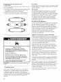
Using the universal cord included with this dryer:
The gas dryer is equipped with a universal cord with
interchangeable plugs.
1. To use the universal cord, select the plug end that fits
your electrical outlet, and plug it into the adapter on the
supply cord.
2. Secure the plug end in place on the cord by aligning
the 2 cover halves over the cord adapter and clipping
them together.
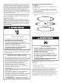
Explosion Hazard
Connect this dryer to a regulated gas supply. Supply
pressure must be in accordance with the Technical
Specifications (see last page}.
Install a shut=off valve.
Securely tighten all gas connections,
if connected to LP, have a qualified person make sure
gas pressure is correct.
Failure to do so can result in death, explosion, or fire.
Before installation, check that the local gas distribution
conditions, nature of gas and pressure, and the adjustment
of the appliance are compatible. Burner information will be
found on the model/serial rating plate inthe door recess of
the dryer. Ifthis information does not agree with the type
of gas available, see your dealer.

Natural Gas:
This dryer is factory adjusted for use with NATURAL GAS (G20),
and no further adjustment should be required at installation.
L.P. Gas:
This dryer is also certified for use with LR (propane or butane)
gases with appropriate conversion. No attempt shall be made to
convert the appliance from the gas specified on the model/serial
rating plate for use with a different gas without consulting the
serving gas supplier.
Conversion must be done by a competent service technician.
Gas conversion kit, part number W10233219, is available for
purchase from your dealer. Full instructions are supplied with
the kit.
Natural gas (France/Belgium}:
This dryer is also certified for France/Belgium for use with
G20/G25 gases (20 mbar/25 mbar) with appropriate conversion.
No attempt should be made to convert this appliance from the
gas specified on the gas rating label for use with a different gas
without consulting the serving gas supplier. Gas conversion must
be done by a qualified gas service technician. Conversion kit, part
number (W10181947) is available for purchase from your dealer.
Full instructions are supplied with the kit.
Supply line requirements:
Provide a rigid gas supply line to the dryer location. It should be
minimum 12.5 mm (1/2") ID. When acceptable to the gas supplier
and local codes, 10 mm (3/8") ID rigid supply line may be used
for lengths under 6.1 m (20'). Pipe-joint compounds resistant to
the action of LR gas must be used.
Gas connection to the dryer itself should be made by means of
a flexible gas hose suitable for the appliance and gas category
in accordance with national installation regulations. If in doubt,
contact the gas supplier. It should be minimum 10 mm (3/8") ID.
A means of restraint should be used between the appliance and
the walt to prevent straining of the rigid gas supply when the
appliance is moved. An appropriate length of chain and a watt
hook is recommended.
The dryer gas inlet connection is a 3/8" NPT thread. An adapter is
supplied for conversion to standard ISO.228-1 thread (3/8" BSP).
Check for leaks by using an approved noncorrosive leak-
detection solution. Bubbles will show a leak. Correct any leak
found. A pressure measurement tapping is provided on the
gas valve within the dryer, accessible after removal of the lower
front panel.
The dryer must be disconnected from the gas supply piping
system during any pressure testing of that system.
Fire Hazard
Use a heavy metal vent.
Do not use a plastic vent.
Do not use a metal foil vent.
Failure to follow these instructions can result in death
or fire.
WARNING: To reduce the risk of fire, this dryer MUST BE
EXHAUSTED OUTDOORS.
[] Following these venting requirements will minimise ducting
air noise.
[] Gas dryers should only be installed in a room if the room
meets the appropriate ventilation requirements specified
in the national installation regulations. Make sure the room
containing the dryer has an adequate air supply for gas
combustion and drying operation. A window or equivalent
means of ventilation must be opened in the room when the
dryer is in use (an equivalent form of opening includes an
adjustable louver, hinged panel, or other means of ventilation
that opens directly to outside air). Adequate ventilation has to
be provided to avoid the backflow of gases into the room from
other fuel-burning appliances, including open fires (i.e.available
airflow into the room should match airflow out from the room).
[] The design of the flue system should be such that any condensate
formed when operating the dryer from cold shall either be retained
and subsequently re-evaporated or discharged. Following these
instructions should adequately meet this requirement.
[] Dryer exhaust must not be connected into any gas vent,
chimney, walt, ceiling, attic, crawtspace, or a concealed space
of a building. Only rigid or flexible metal vent shall be used for
exhausting.
[] Do not use an exhaust hood with a magnetic latch.
[] Do not install flexible metal vent in enclosed walls, ceilings,
or floors.
[] Only a 102 mm (4") heavy metal exhaust vent and clamps
may be used.
Heavy metal 0 102 mm
exhaustvent (4")
[] Use clamps to seat all joints. Vent must not be connected or
secured with screws or other fastening devices which extend
into the interior of the vent and catch lint. Do not use duct tape.
improper venting can cause moisture and lint to collect
indoors, which may result in:
[] Moisture damage to woodwork, furniture, paint, wallpaper,
carpets, etc.
[] Housecleaning problems and health problems.
IMPORTANT: Observe all governing codes and ordinances.
Use a heavy metal vent. Do not use plastic or metal foil vent.
Rigid metal vent is recommended for best drying performance
and to avoid crushing and kinking.
Flexible metal vent must be fully extended and supported when
the dryer is in its final position. Remove excess flexible metal vent
to avoid sagging and kinking that will result in reduced airflow
and poor performance.
The total length of flexible metal vent should not exceed 2.4 m
(7,Y4ft.).
An exhaust hood should cap the vent to keep rodents and
insects from entering the building.
Exhaust hood must be at least 305 mm (12") from the ground
or any object that may be in the path of the exhaust (such as
flowers, rocks, bushes, or snow).
If using an existing vent system, clean lint from the entire length
of the system and make sure exhaust hood is not plugged with
lint. Replace any plastic or metal foil vent with rigid metal or
flexible metal vent.
7

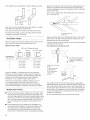
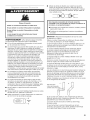
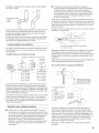
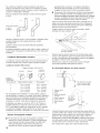
Plan installation to use the fewest number of elbows and turns.
A ...............
OW
I I A. ood
B. Better
Allow as much room as possible when using elbows or making
turns. Bend vent gradually to avoid kinking.
Vent outlet is located at the center of the bottom dryer back.
The vent can be routed up, down, left, right, behind the dryer,
or straight out the back of the dryer.
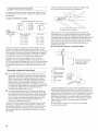
Vent System Length
Maximum length of vent system depends upon the type of vent
used, number of elbows, and type of exhaust hood.
Maximum Vent Length
102 mm (4") Exhaust Hoods
Box Louvered 64 mm (Z/2") Angled
Rigid Metal Vent
No. of 900 turns Box Hood and Louvered Style Angled Hood Style
0 39.6 m (130 ft.) 39.3 m (129 ft.)
1 38.1 m (125 ft.) 36.3 m (119 ft.)
2 35.1 m (115 ft.) 33.2 m (109 ft.)
3 32.3 m (106 ft.) 30.5 m (100 ft.)
4 29.9 m (98 ft.) 28 m (92 ft.)
If dryer is installed in a confined area, such as a bedroom,
bathroom, or closet, provision must be made for enough air
for combustion and ventilation. (Check governing codes and
ordinances.) See "Recessed Area and Closet Installation
Instructions" in the "Location requirements" section.
A 102 mm (4") outlet hood is preferred. However, a 64 mm
(2W') outlet exhaust hood may be used. A 64 mm (2W')
outlet creates greater back pressure than other hood types.
For permanent installation, a stationary vent system is required.
[] A main vent can be used for venting a group of dryers. Main
vent should be sized to remove 5663 I/min (200 CFM) of air
per dryer. Large-capacity lint screens of proper design may be
used in the main vent if checked and cleaned frequently. The
room where the dryers are located should have make-up air
equal to or greater than the airflow of all the dryers in the
room.
[] A back-draft damper kit is needed and is available from a
commercial laundry distributor; it should be installed in the
vent of each dryer to keep exhausted air from returning
into the dryers and to keep the exhaust in balance within
the main vent. Unobstructed return air openings are required.
Each vent should enter the main vent at an angle pointing in the
direction of the airflow. Vents entering from the opposite side
should be staggered to reduce the exhausted air from interfering
with the other vents.
The maximum angle of each vent entering the main vent should
be no more than 30°.
A. Individual dryer vent
B. Main vent
Keep air openings free of dry cleaning fluid fumes. Fumes create
acids which, when drawn through the dryer heating units, can
damage dryers and items being dried.
A clean-out cover should be located on the main vent for periodic
cleaning of the vent system.
If an exhaust hood cannot be used:
Min. 300 mm (12") clearance
above any accumulation
of snow, ice, or debris such
as leaves.
A. Exhaust hood or elbow
B. Wall
C. Main collector vent
D. Horizontal vent
E. 180° sweep elbow
F. Vertical vent
G. Roof
610 mm(24")
min. above
highestpoint
of building
G
C
The outside end of the main vent should have a sweep elbow
directed downward. If the main vent travels vertically through the
roof, rather than through the wall, install a 180° sweep elbow on
the end of the vent at least 610 mm (2 ft.) above the highest part
of the building. The opening in watt or roof shall have a diameter
13 mm (1/2") larger than the vent diameter. The vent should be
centered in the opening.
Do not install screening or cap over the end of the vent.

INSTALLATIONINSTRUCTIONS- GASDRYER
i!! ¸;ijj
Excessive Weight Hazard
Use two or more people to move and install dryer.
Failure to do so can result in back or other injury.
NOTE: Slide dryer onto cardboard or hardboard before moving
to avoid damaging floor covering.
1. Using two or more people, move dryer to desired installation
location.
2. Take tape off front corners of dryer. Open dryer and remove
the literature and parts packages. Wipe the interior of the
drum thoroughly with a damp cloth.
3. Take two of the cardboard corners from the carton and place
them on the floor in back of the dryer. Firmly grasp the body
of the dryer and gently lay it on its back on the cardboard
corners.
4. With one of the legs in hand, check the ridges for a diamond
marking. That's how far the leg is supposed to go into the
hole.
5. Start to screw the leveling legs into the holes by hand. (Use
a small amount of liquid detergent to lubricate the screw
threads so it is easier to turn the legs.) Use a 25 mm (1")
wrench or socket wrench to finish turning the legs until you
reach the diamond mark. Then fit a protective foot boot over
each foot.
6. Now stand the dryer up.
7. Remove cardboard or hardboard from under dryer. Adjust the
legs of the dryer up or down until the dryer is level.
Excessive Weight Hazard
Use two or more people to move and install dryer.
Failure to do so can result in back or other injury.
1. Remove red cap from gas pipe.
2. Connect gas supply to dryer. If the flexible gas hose has 3/8"
BSP thread, use the supplied conversion thread adapter. Use
pipe-joint compound resistant to the action of LR gas for gas
connections.
If necessary for service, open the toe panel. Use a putty knife
to press on the 2 toe panel locks located at the top of the toe
panel. Pull downward on the toe panel to open. Toe panel is
hinged at the bottom.
3. Open the shutoff valve in the gas supply line.
4. Test all connections by brushing on an approved noncorrosive
leak-detection solution. Bubbles will show a leak. Correct any
leaks found.
1. Using a 102 mm (4") clamp, connect vent to exhaust outlet
in dryer. If connecting to existing vent, make sure the vent is
clean. The dryer vent must fit over the dryer exhaust outlet
and inside the exhaust hood. Make sure the vent is secured
to exhaust hood with a 102 mm (4") clamp.
2. Move dryer into final position. Do not crush or kink vent. Make
sure dryer is level.
3. Check to be sure there are no kinks in the flexible gas line.
1.
With dryer in final position place level on top of the
dryer, first side to side, then front to back. If the dryer is
not level, adjust the legs of the dryer up or down until the
dryer is level.
Electric Shock Hazard
This dryer must be earthed.
Securely tighten all electrical connections.
Failure to do so can result in death, fire, or
electric shock.
2. Plug into an earthed outlet.
3. Check dryer operation:
Press the selection button for a full cycle and let the dryer run
for at least five minutes. Dryer will stop when time is used up.
NOTE: Dryer door must be closed for dryer to operate.
When door is open, dryer stops, but timer continues to run.
To restart dryer, close door and press a cycle button.
4. If the burner does not ignite and there is no heat inside the
dryer, shut off dryer for five minutes. Check that all gas supply
valves are in the "ON" position and that the electrical cord is
plugged in. Repeat five-minute test.
9

MAINTENANCEINSTRUCTIONS
Maintenance instructions:
[] Clean lint screen after each cycle.
[] Removing accumulated lint (disconnect dryer from electricity
and gas supplies before starting this task):
• From inside the dryer cabinet:
Lint should be removed every 2 years or more often,
depending on dryer usage. Cleaning should be done
by a qualified person.
• From the exhaust vent:
Lint should be removed every 2 years, or more often,
depending on dryer usage.
If dryer does not operate, check the following:
[] Electric supply is connected.
[] Circuit breaker is not tripped or fuse is not blown.
[] Door is closed. Listen closely to hear door switches activate.
[] Selected cycle button has been pressed firmly and display
shows cycle time.
[] Check that gas supply shutoff valves are set in open position.
If you need assistance:
Contact your authorized Maytag _'_Commercial Laundry distributor
or visit: www.MaytagCommercialLaundry.com. When you call,
you will need the dryer model number and serial number.
Both numbers can be found on the serial-rating plate located
on your dryer.
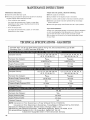
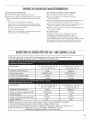
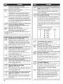
TECHNICALSPECIFICATIONS.GASDRYER
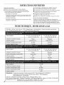
220-240V-50Hz 1ph 3A max. 1P24Clothes capacity: 9.0 kg max. Sound pressure level, Lpa: 58 dBA
(uncertainty, Kpa: +/-10 dBA) Total mass: 68 kg max.
European Country: CH, CZ, CY, ES, GB, GR, HR,
{E, {T, PT, S{, SK, TR
European Gas Category: II2H3+
Gas Flow Rate: 0.562703 m3/hr
Supply Pressure (G20): 20 mbar
Factory Adjusted Pressure: 7.4 mbar
European Country: CH, CZ, CY, ES, GB, GR, HR,
{E, {T, PT, S{, SK, TR
II2H3+
28-30 mbar
N/A
37 mbar
N/A
FR, BE
I2E+
20 mbar
25 mbar
N/A
NOTE: Conversion kit: From Natural Gas to LP Gas: Whirlpool Part No. W10233219.
Conversion kit: From Natural Gas to Natural Gas - France/Belgium: Whirlpool Part No. W10181947.
Manufacturer: Whirlpool Corporation, Benton Harbor, Michigan 49022, U.S.A.
Manufacturing Site: Whirlpool Corporation, 1300 Marion-Agosta Rd., Marion, OH 43302, U.S.A.
EU representatives: Maytag UK Ltd., 2 St. Annes Blvd., Redhill, RH1 lAX, UK
& Bauknecht Hausger&te GmbH, D-73614 Schorndorf, Germany
European Gas Category:
Butane Supply Pressure (G30):
Adjusted Pressure:
Propane Supply Pressure (G31):
Adjusted Pressure:
European Country:
European Gas Category:
Supply Pressure (G20):
Supply Pressure (G25):
Adjusted Pressure:
CY, CZ, DK, EE, FI, GR, HU, IT,
NO, RO, SE, SK, TR
II2H3B/P
0.562703 m3/hr
20 mbar
7.4 mbar
CY, CZ, DK, EE, F{, GR, HU, {T,
NO, RO, SE, SK, TR
II2H3B/P
30 mbar
N/A
30 mbar
N/A
10

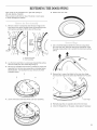
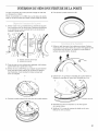
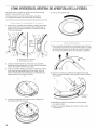
REVERSINGTHEDOORSWING
Door swing can be changed from a right-side opening to
left-side opening, if desired.
Place a towel or soft cloth on top of the dryer or work space
to avoid damaging the surface.
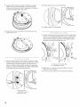
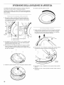
5. Rotate outer door 180°.
2_
3.
Remove 3 of the 4 screws that hold the door hinge on the
front panel of the dryer. Partially loosen the remaining screw
with keyhole opening and lift the door off the screw.
\
Loosen
screw
with
keyhole
opening
A. Dryer front panel
B. Door assembly
Lay the door assembly on a previously prepared flat surface
with the inside (inner door assembly) facing up.
Remove the 6 Phillips-head screws to release the outer door
assembly from the inner door assembly, as indicated below.
See illustration. It is important that you remove only the 6
indicated screws.
4. Lift the inner door assembly off the outer door assembly.
2_
(J
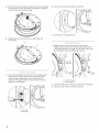
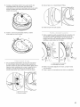
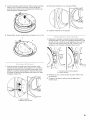
Use a small flat-blade screwdriver to remove 2 plug strips
from the inner door. Slide the head of the screwdriver under
the plugs, being certain not to scratch the inner door surface.
Lift up.
Remove the 4 screws that attach to the inner door hinge
and move the hinge to the other side. Reinstall the 4 screws.
Door hinge
3. Reinstall plug strips on opposite side of the inner door.
4. Check for fingerprints on the glass. Clean glass if necessary.
11

5. Place the inner door assembly inside the outer door assembly.
To fit correctly, the inner door assembly edge fits completely
inside the outer door assembly edge.
2. Remove the strike using a Phillips screwdriver.
6.
1.
Reassemble the inner and outer door assemblies with
the 6 screws.
Use a small flat-blade screwdriver to remove plug strip from
the dryer door opening. Slide the head of the screwdriver
under the plugs, being certain not to scratch the dryer
surface. Lift the plastic strip from the dryer slowly to avoid
distortion of the plug strip.
3. Insert strike on the opposite side.
1.
2.
3.
Reattach door to dryer front panel with the 4 screws.
Partially install the screw with keyhole opening first, and fit
the keyhole opening in the hinge over the screw. Then install
the remaining 3 screws and tighten all 4 screws.
Instafl this
screw first
A. Dryerfront panel
B. Door assembly
Check for fingerprints on the glass. Clean glass if necessary.
Close door and check that it latches securely.
A. Plug strip
B. Door strike
12

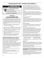
ELECTRONICCONTROL SETUP
Electric Shock Hazard
Disconnect power before servicing.
Replace all parts and panels before operating.
Failure to do so can result in death or
electrical shock.
iMPORTANT
Electrostatic Discharge (_:SD)
Sensitive Electronics
ESD is present everywhere. ESD may damage or weaken the
electronic control assembly. The new control assembly may
appear to work well after repair is finished, but failure may
occur at a later date due to ESDstress.
[] Use an anti-static wrist strap. Connect wrist strap to green
earth connection point or unpainted metal in the appliance.
-OR-
Touch your finger repeatedly to a green earth connection point
or unpainted metal in the appliance.
[] Before removing the part from its package, touch the
anti-static bag to a green earth connection point or
unpainted metal in the appliance.
[] Avoid touching electronic parts or terminal contacts; handle
electronic control assembly by edges only.
[] When repackaging failed electronic control assembly in
anti-static bag, observe above instructions.
GENERAL USER iNFORMATION
"out of order" showing in display
This condition indicates the dryer is inoperative. Diagnostic or failure
code will follow the scrolling message.
"0 Minutes" showing in display
This condition indicates the dryer cannot be operated. Coins
dropped or debit inputs during this condition will be stored in
escrow but cannot be used until normal operation is restored by
opening and closing the door. Ifa door switch fails, it must be
replaced before normal operation can be restored.
Cold Start {initialfirst use)
Dryer is programmed at the factory as follows:
[] 45 minutes dry time for PN models; 5 minutes per coin for
PD models.
[] 1.50 dry price (fixed cycle with top off - PD Models).
[] 0.00 dry price (fixed cycle - PN Models).
Warm Start (after power failure)
A few seconds after power is restored, if a cycle was in progress
at the time of the power failure, "RESELECT CYCLE" will flash
in the display. This isto indicate the need for a fabric setting
button to be pressed to restart dryer.
Pricing
After the door is opened and closed following the completion of
a cycle, the display indicates the cycle price (unless set for free
operation). As coins or debit inputs arrive, the display will change
to lead the user through the initiation of a cycle.
There are four (4)types of pricing:
Fixed "Vend" Pricing
A dryer set up for "Fixed Cycle" operation can only accept
additional time accumulated by increments equal to the length of a
complete dry cycle. A maximum of 99 minutes may be purchased;
no additional credit is given when 99 minutes is in the display.
Accumulator Pricing
If the price is set to one coin 1,then accumulator mode is in effect.
Cycle time can be purchased one coin at a time (PD models) up to
the maximum time of 99 minutes.
Fixed Cycle With Top Off Pricing
A dryer set to offer "Top Off" capability will allow time to be added
to an existing dry cycle in increments equal to the number of
minutes of dry time per coin (coin 1), up to 99 minutes, regardless
of the cost required to start the dryer. No credit is given for coins
or debit inputs entered when the control is displaying 99 minutes.
PN Models Set Up As PR: in Enhanced Debit Mode, the top off
price can be set independently (seeVALUE OF COIN 2), and the top
off time is calculated according to the following equation:
top off price = top off time
full cycle price full cycle length
Hundredth increment offset is not applied to top off purchases.
PH Models
The factory has preset the cycle price to zero. When this happens,
"SELECT CYCLE" wilt appear rather than a cycle price. Any cycle
started as a free cycle will automatically terminate when the door
is opened.
Debit Card Ready
This dryer has a control that is debit card ready, but the dryer is not.
13

CONTROLS_UPPROCEDURES
IMPORTANT: Read all instructions before operating.
The fabric setting buttons along with the digital display are used
to set up the dryer controls.
The display can contain 4 numbers and/or letters and a decimal
point. These are used to indicate the set-up codes and related code
values available for use in programming the dryer.
Now to use the buttons to program the controls
1. The WHITES AND COLORS button is used to adjust the
values associated with set-up codes. Pressing the button will
increment the value by one (1). Rapid adjustment is possible
by holding down the button.
2. The PERM. PRESS button advances the display through the set-
up codes. Pressing the button will advance the display to the next
available set-up code. Holding down the button will automatically
advance through the set-up codes at a rate of one (1)per second.
3. The DELICATES button is used to select or deselect options.
Start Operating Set-Up
mPD Models: Insert service door key,turn, and lift to remove
access door.
mPN Models: Remove the AA1 jumper from the control board (see
procedure below) or use the Service Access Code below. Once the
debit card reader is installed (according to the reader manufacturer's
instructions), the set-up mode can be entered by inserting a manual
set-up card (supplied by the reader manufacturer) into the card slot.
Ifmanual set-up card is not available, manual set-up mode cannot
be entered. However, diagnostic mode can be entered by removing
connector AA1 on the circuit board.
IMPORTANT: The console must not be opened unless power is
first removed from the dryer. Toaccess connector AA1 :
-> Unplug dryer or disconnect power.
-> Open console, disconnect plug on AA1, close console.
-> Plug in dryer or reconnect power.
mPN Models Equipped with Programming Switch: Insert access
panel key and turn counterclockwise.
mPN Models with Gen. 2 Debit Card Reader: Once a Gen. 2 debit
card reader is installed (according to the reader manufacturer's
instructions), the set-up mode can only be entered by inserting
a manual set-up card (supplied by the reader manufacturer)
into the card slot.
If manual set-up card is not available, only diagnostic mode
can be entered.
mAlternate method of entering Set-up Mode by entering Service
Access Code: This code can be entered to access set-up mode
without removing the console on dryers just removed from the
carton, or not yet programmed. The Service Access Code only
functions on dryers set up for 0 vend price without any Special
Pricing setup, and the Coin/Debit Option must be set to "J._d'.
Ifthe dryer is not in failure mode, the door must be opened to
proceed. Using only the three bottom buttons (numbered 1,2,
and 3 from left to right):
1. Press 2 for longer than 2 seconds but less than 10 seconds.
2. Press 1 & 3 simultaneously for 2 seconds. Display shows S 3.
3. Press 1 & 2 simultaneously. Display shows S 4.
4. Press 2 & 3 simultaneously. Display shows S 5.
5. Press 2.
6. Wait at least 2 seconds, but not more than 15 seconds,
then press in succession: 3, 2, 1,3.
The dryer is now in the set-up mode.
Before proceeding, it is worth noting that, despite attthe options
available, an owner can simply choose to uncrate a new commercial
dryer, hook it up, plug it in, and have a dryer that operates. NOTE:
PD models require a payment system or OPL kit to be installed prior
to operation.
mPD dryers are pre-set at the factory for fixed cycle price with top off.
mPN dryers are pre-set for fixed cycle operation, and they can be
run without payment.
14
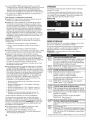
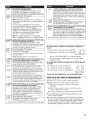
DISPLAY
After the dryer has been installed and plugged in,the dispiay will
show "0 minutes."
Once the dryer has been plugged in and the dryer door opened
and closed, the display wilt show the vend price. PN models are
factory preset for free cycles; the display will flash "SELECT CYCLE."
PD Models
WHITES PERM.
AND COLORS PRESS DELICATES
m _ m
PN Models
WHITES PERM.
AND COLORS PRESS DELICATES
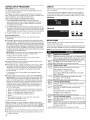
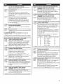
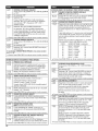
SST-UP CODSS
FOR PN MODELS: The set-up codes are the same as for the PD
models except where noted.
Theset-up code is indicated by the one or two left-hand characters.The
set-up code value is indicated by the two or three right-hand characters.
NOTE: The first line of each code indicates the factory default.
REGULAR CYCLE PRICE
¢.Tn ¢.T
c1_ Representsthe numberofcoins(coin1); mayadjustfrom 0-39
(Seeb.xxset-upfor VALUEOFC01N1).Advancefrom 0-39 by
pressingWHITESANDCOLORS.Factorydefaultof 6x coin1.
c_J__ PNMODELSONLY:Factorydefaultof 6 00,or 0coins.
-> PressPERM.PRESSbuttononceto advanceto nextcode.
L_u S REGULAR DRY TIME
/ _ Representsthe numberofminutespercoin(coin 1).
Factorydefaultd 5 minutespercoin.
Example:6 coinsx 5 minutes=30 minutes.
BypressingtheWHITESANDCOLORSbutton,valueadjusts
from 1-99 minutes.
_ PNMODELS:Representsthe cyclelengthforfreecycles.
Asexample:"7 45" =45 minutes.
-> PressPERM.PRESSbuttononceto advanceto nextcode.
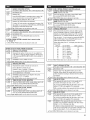
L_U u TYPE OF DRYER PRICING
oc_ FixedCyclewith TopOff.Fordetaileddescription,seeGeneral
UserInformation.
J-_c _- FixedCycle.Fordetaileddescription,seeGeneralUser
Information.
UseDELICATESbuttonto makethisselection.
PNMODELS:FactorydefaultofFC.
-> PressPERM.PRESSbuttononceto advanceto nextcode.
_u u CYCLE COUNTER OPTION
ThisoptioniseitherSELECTED"ON"or NOTSELECTED"OFE"
-_J-_L"""""_NotSelected"OFE"
_-7_ Selected"ON"and not ableto bedeselected.PressDELICATES
button3 consecutivetimes to select"ON."Onceselected"ON"
it cannotbedeselected.
-> PressPERM.PRESSbuttononceto advanceto nextcode.

_uu
MONEY COUNTER OPTION
This option iseitherSELECTED"ON"or NOTSELECTED"0rE"
i._ NotSelected"0rE"
I1"_11 -
i._ Selected"ON."
PressDELICATESbutton3 consecutivetimes to select"ON"
and3 consecutivetimes to remove(NotSelected"OFF").
Counterresetsby goingfrom "OFF"to "ON."
I1--1"_1
i._ Selected"ON"andnot ableto bedeselected.
Toselect"ON"and not ableto bedeselected,first select"ON,"
thenwithin two secondspressDELICATEStwice,WHITESAND
COLORSonce,andexittheset-upmode.
•._ PressPERM.PRESSbutton onceto advanceto nextcode.
J__.uu SPECIAL PRICING OPTION
This option iseitherSELECTED"ON"or NOTSELECTED"OFE"
_aa
c. _ NotSelected"ORE"
"_co
_--.-L_ Selected"ON." PressDELICATESbutton oncefor this
selection.
ifSPECIALPRICINGOPTIONisselected, thereis accessto codes
"3." through "g."
-->PressPERM.PRESSbutton onceto advanceto nextcode.
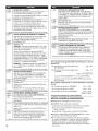
OPTIONSTO USEIFSPECIALPRICINGIS SELECTED:
_nC
=_.u u SPECIAL CYCLE PRICE
=-7._ Representsthe numberof coins(coin 1); mayadjustfrom
0-39. (Seeb.xxsetupfor VALUEOFCOIN1).Advancefrom
0-39 bypressingWHITESANDCOLORS.Factorydefaultof
6x coin1.
PNMODELS:Factorydefaultof 0 coins.
--->PressPERM.PRESSbuttononceto advanceto nextcode.
U
_.u S SPECIAL DRY TIME
%1._ Representsthe numberof minutespercoin(coin 1).
Factorydefaultof 5minutespercoin.
Example:6 coinsx 5 minutes=30 minutes.
BypressingtheWHITESANDCOLORSbutton,thevane
canbeadjustedfrom 1-99 minutes.
_1._ PNMODELS:Representsthecyclelengthfor freecycles.
Asexample:"4 45"=45 minutes.
-e PressPERM.PRESSbuttononceto advanceto nextcode.
L.-_nn
u u TIME-OF-DAY CLOCK, MINUTES
C FI FI
-_.J-_C"""""_This isthe TIME-OF-DAYCLOCK,minutesetting;select0-59
minutesbypressingWHITESANDCOLORSbutton.
-> PressPERM.PRESSbuttononceto advanceto nextcode.
LT FI FI
u u TIME-OF-DAY CLOCK, HOURS
NOTE:Usesthe 24 hr. clock.
¢.Tm r_ 1
c,.J-_C--------------_This istheTIME-OF-DAYCLOCK,hour setting;select0-23
hoursby pressingWHITESANDCOLORSbutton.
-e PressPERM.PRESSbuttononceto advanceto nextcode.
OPTIONSTOUSEIFSPECIALPRICINGISSELECTED(continued):
_u u SPECIAL PRICE START HOUR
NOTE:Usesthe 24 hr.clock.
/._ Thisisthe starthour,0-23 hours.SelectSTARTHOUR
by pressingWHITESANDCOLORSbutton.
--->PressPERM.PRESSbutton onceto advanceto nextcode.
cco_.uu SPECIAL PRICE STOP HOUR
NOTE:Usesthe 24 hr.clock.
o. A_,,,,_ This isthe stop hour; 0-23 hours.SelectSTOPHOUR
by pressingWHITESANDCOLORSbutton.
--->PressPERM.PRESSbutton onceto advanceto nextcode.
I u SPECIAL PRICE DAY
n _n This representsthe dayof the weekandwhetherspecial
pricing isselectedfor thatday.A numberfollowed by "0"
indicatesno selectionthat particularday (9.10).A number
followedbyan "S" indicatesselectedfor thatday(9.1S).
Daysofweek(1-7) canbechosenbypressingthe WHITES
ANDCOLORSbutton.Press DELICATESbutton onceto
selectspecialpricingfor eachdaychosen.
Whenexitingsetupcode"9.," the displaymust showcurrent
dayofweek:
DISPLAY DAYOFWEEK CODE(selected)
10 Day1 =Sunday 1S
20 Day2 =Monday 2S
30 Day3 =Tuesday 3S
40 Day4 =Wednesday 4S
50 Day5 =Thursday 5S
60 Day6 =Friday 6S
70 Day7 =Saturday 7S
-> PressPERM.PRESSbutton onceto advanceto nextcode.
!]_.uu
'-iRa
-_CF
H.___
VAULT VIEWING OPTION
This optionis eitherSELECTED"ON"or NOTSELECTED"OFE"
NotSelected"OFE"
Selected"ON."PressDELICATESbutton oncefor this
selection.Whenselected,the moneyand/orcyclecounts
will beviewable(if counting isselected)whenthe coinbox
is removed.
-e PressPERM.PRESSbuttononceto advanceto nextcode.
_L_jU__ VALUE OF COIN 1
_._ This representsthe valueofcoin 1 in the quantityof 5%
incrementsofthe largercoinvalue.5x 5% =25%.
BypressingtheWHITESANDCOLORSbutton,thereis the
optionof 1-199 forthe quantityof 5% increments.
With coin slideactivation,this representsthetotal vendprice.
-) PressPERM.PRESSbuttononceto advanceto nextcode.
F "_n
,_.._cu VALUE OF COIN 2
F '3R
This representsthe valueofcoin 2 in the quantityof 5%
incrementsofthe largercoinvane. 20x 5% = 100%.
BypressingtheWHITESANDCOLORSbutton,thereis the
optionof 1-199 forthe quantityof 5% increments.
F FIC
c._ PNMODELS:This representsthe valueofcoin 2 in the
quantityof 5% incrementsofthe largercoinvalue.Factory
default= 5x 5% ofthe largercoinvalue.
PNMODELSUSINGENHANCEDDEBIT:This representsthe
vane oftop off in quantityof 5% incrementsof the largercoin
value.Factorydefault=5x 5%of the largercoinvalue.
-->PressPERM.PRESSbuttononceto advanceto nextcode.
15

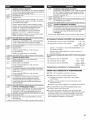
C_.uu COIN SLIDE OPTION
This option iseitherSELECTED"ON"or NOTSELECTED"OFE"
Replacementof metercasewill beneededfor coinslidemounting.
o.u_ NotSelected"OFE"
d._ Selected"ON."
NOTE:This option needsto besetto "00" unlessthe
metercasehasbeenchangedto accepta coinslidedevice.
PressDELiCATESbutton3 consecutivetimes forthis
selection.Whencoinslide mode isselected,set"b." equalto
valueof slidein coins.Set"6 xx" (REGULARCYCLEPRICE)
and"3.xx" (SPECIALCYCLEPRICE)to numberof slide
operations.6 01 &3.01 =1 slidepush.
NOTE:ifthe installersetsup "CS"onacoin drop model,
itwill not registercoins.
-> PressPERM.PRESSbutton onceto advanceto nextcode.
Cnn
J_.uu ADD COINS OPTION
This option iseitherSELECTED"ON"or NOTSELECTED"OFE"
This optioncausesthe customerdisplayto showthe number
of coins (coin 1)to enter,ratherthanthe amount.
cnn
c._ NotSelected"OFE"
C'_l-
c._ Selected"ON."
PressDELiCATESbutton3consecutivetimesfor this selection.
PNMODELS:This optionis not selectable.
-> PressPERM.PRESSbutton onceto advanceto nextcode.
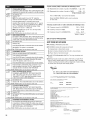
If" I
,__co COIN/DEBIT OPTION
II- t
,j._ Bothcoin anddebit selected.(NOTAVAILABLE)
IF
u._ Coinsselected,debit disabled.
PressDELICATESbutton3consecutivetimesforthisselection.
I I
,.J.-L=_o DebitCardselected,coin disabled.Defaultfor PN models,
andfor PNoperation,must besetasJ._d.
PressDELICATESbutton3consecutivetimesforthisselection.
,__._ EnhancedDebitis self-selectedwhen aGeneration2 card
readeris installedinthe dryer.The"Ed"option cannotbe
manuallyselectedor deselected.(NOTAVAILABLE)
-e PressPERM.PRESSbutton onceto advanceto nextcode.
c_.juu PRICE SUPPRESSION OPTION
This option iseitherSELECTED"ON"ORNOTSELECTED
"OFE" This optioncausesthe customerdisplayto show
"AVAILABLE"or "ADD"ratherthanthe amountof money
to add.(Usedmainly in debitinstallations.)
c._ NotSelected"OFE"
o c Selected"ON."PressDELICATESbuttononceforthis selection.
c._
-> PressPERM.PRESSbutton onceto advanceto nextcode.
_.c c CLF..ARESCROW OPTION
This option iseitherSELECTED"ON"ORNOTSELECTED
"OFE"Whenselected,moneyheldin escrowfor 30 minutes
withoutfurther escrow or cycleactivitywiii becleared.
n.t_2_ Selected"ON."
nn NotSelected"OFE"PressDELiCATESbuttononceto deselect
this option.
-> PressPERM.PRESSbutton onceto advanceto nextcode.
, t n n HUNDREDTH INCREMENT OFFSET
IU.IU U
L.,.J__ This representsthe hundredthincrementpriceoffsetused
in Generation2 (EnhancedDebit)PNmodelssetup with card
reader.Choosefrom 0-4 hundredthsby pressingthe WHITES
ANDCOLORSbutton.(NOTAVAILABLE)
PressPERM.PRESSbutton onceto advanceto nextcode.
If cycle counter (90C) is selected, the following is true:
1 00 Represents the number of cycles in HUNDREDS. 102 = 200
2 00 Represents the number of cycles in ONES. 2 2,5= 25
TOTAL CYCLES = 225
This is "VIEW ONLY" and cannot be cleared.
Press the PERM. PRESS button once to advance
to next code.
If money counter (1.0C or 1.C0) isselected, the following is true:
3 O0 Currency amount in HUNDREDS. 3 01 = 100.00
4 O0 Currency amount in ONES. 4 68 = 68.00
5 O0 Currency amount in HUNDREDTHS. 5 7,5= 00.75
TOTAL = 168.75
END OF SET-UP PROCEDURES
F.X|T FROM SET-UP MODE
[] PD MODELS: Reinstall access door.
[]
[]
PN MODELS where AA1 plug was removed:
1. Unplug dryer or disconnect power.
2. Open console, reinsert jumper into AA1, close console.
3. Plug in dryer or reconnect power.
PN WITH PROGRAMMING SWITCH: Turn key clockwise and
remove.
If Service Access Code was used to enter set-up mode: From
Set-up Code 8, press button #1 for 4 seconds, wait 2 minutes
without touching any buttons (without diagnostic modes running),
or power down the dryer, then reapply power.
EU =DECLARATION OF CONFORMITY
CE - DECLARATION DE CONFORMITE
wEr.,,.,) BAUKNECHT ltAUSGERATE Gmbl I, D-73614 Schorndorf
*¢_,_._,,,ti_g_,,,l,,,_,,,*.,,!iWII/RLPOOI, EUROP_ S.r,I [-21025 COMERIO
declare under our sole responsibility that the product
&;elatom _,u_ no#e p, opre r _vmmabihh que le p, od_ it
dryer Maytag MDG25PD
b,;,h.. _,z,o
Maytag MDG25PN
to which this declaration relates is in conlbriniD" with the following standard(s) or other
normative document(s)
EN 60335-1:2002+AI+A2rA11+A12+AI3+A14
EN 60335-2-11:2003+Al+A2+AI I
EN 12752-1:1999
EN 62233:2008
EN ISO 10472-1:2008
EN ISO 10472-2:2008
EN 55014-1:2006+A1:2009
EN 55014-2:1997+Corrigendum :1997+A1:2001+A2:2008
EN 61000-3-/2:2005
EN 61000-3-11:2000
following the provisions of Directive(s):
2006/42/EC MACHINERY DIRECTIVE ((7_ D#,<ti,, _t._h._.2
2009/142/EC EUROPEAN GAS AI?IiLIANCE DIRECTIVE
2004/108/EC ELECTROMAGNETIC COMPATIBILrr Y DIRECTIVE _(-iv=_i_ c,,._m_ili_
2002/95/EC ROHS DIRECTIVE ((/:7; D_.cm e Ro//9
2002/96/EC WEEE DIRECTIVE (c_,_¸z_i_i_ _Llv
r pr sell_*db_
Schorndorh 18,10,2011 Franz Hartntann Karl-Dieter Klingenstein
Place and da_e: Director PDC FC EMEA Product Approval
/_,_,__, GPO, Schorndorf
16

MAYTAG ® COMMERCIAL WASHER, DRYER, STACKED DRYER/
DRYER, COMMERCIAL STACK LAUNDRY, AND MULTi-LOAD
COiN OPERATED COMMERCIAL WASHERS AND DRYERS
WAR NTY
LiMiTED WARRANTY ON PARTS
For the first five years from the date of purchase, when this commercial appliance is installed, maintained and operated according to the
instructions attached to or furnished with the product, Maytag brand of Whirlpool Corporation (thereafter "Maytag") will pay for factory
specified parts or original equipment manufacturer parts to correct defects in materials or workmanship. Proof of original purchase date
is required to obtain service under this warranty.
iTEMS MAYTAG WiLL NOT PAY FOR
1. All other costs including labor, transportation, or custom duties.
2. Service calls to correct the installation of your commercial appliance, to instruct you how to use your commercial appliance, to
replace or repair fuses, or to correct external wiring or plumbing.
3. Repairs when your commercial appliance is used for other than normal, commercial use.
4. Damage resulting from improper handling of product during delivery, theft, accident, alteration, misuse, abuse, fire, flood, acts of
God, improper installation, installation not in accordance with local electrical or plumbing codes, or use of products not approved
by Maytag.
5. Pickup and Delivery. This commercial appliance is designed to be repaired on location.
6. Repairs to parts or systems resulting from unauthorized modifications made to the commercial appliance.
7. The removal and reinstallation of your commercial appliance if it is installed in an inaccessible location or is not installed in
accordance with published installation instructions.
8. Chemical damage is excluded from all warranty coverage.
9. Changes to the building, room, or location needed in order to make the commercial appliance operate correctly.
10. Repairs made by a Non-Whirlpool authorized Service Technician.
DiSCLAiMER OF iMPLiED WARRANTIES; LiMiTATiONS OF REMEDIES
CUSTOMER'S SOLE AND EXCLUSIVE REMEDY UNDER THiS LiMiTED WARRANTY SHALL BE PRODUCT REPAIR AS PROVIDED
HEREIN. iMPLiED WARRANTIES, INCLUDING WARRANTIES OF MERCHANTABiLiTY OR FITNESS FOR A PARTICULAR PURPOSE,
ARE LIMITED TO ONE YEAR OR THE SHORTEST PERIOD ALLOWED BY LAW. WHIRLPOOL SHALL NOT BE LIABLE FOR
INCIDENTAL OR CONSEQUENTIAL DAMAGES. SOME STATES AND PROVINCES DO NOT ALLOW THE EXCLUSION OR LiMiTATION
OF INCIDENTAL OR CONSEQUENTIAL DAMAGES, OR LIMITATIONS ON THE DURATION OF IMPLIED WARRANTIES OF
MERCHANTABILITY OR FITNESS, SO THESE EXCLUSIONS OR LIMITATIONS MAY NOT APPLY TO YOU. THIS WARRANTY GIVES
YOU SPECIFIC LEGAL RIGHTS AND YOU MAY ALSO HAVE OTHER RIGHTS, WHICH VARY FROM STATE TO STATE OR PROVINCE
TO PROVINCE.
If you need service, please contact your authorized Maytag ®Commercial Laundry distributor. To locate your authorized Maytag ®
Commercial Laundry distributor, or for web inquiries, visit www.MaytagCommercialLaundry.com.
1/11
For written correspondence:
Maytag ®Commercial Laundry Service Department
2000 M-63 North
Benton Harbor, Michigan 49022 USA
17

SECURITEDUSECHE.LINGE
Votre securite et celle des autres est tres importante.
Nous donnons de nombreux messages de s_curite importants dans ce manuel et sur votre appareil m_nager. Assurez-vous de
toujours lire tousles messages de s_curite et de vous y conformer.
Voici le symbole d'alerte de s_curit&
Ce symbole d'alerte de s_curit_ vous signale les dangers potentiels de d_c_s et de blessures graves h vous
et h d'autres.
Tous les messages de securite suivront le symbole d'alerte de s_curite et le mot "DANGER" ou
"AVERTISSEMENT". Ces mots signifient •
Risque possible de d6cbs ou de blessure grave si vous ne
suivez pas imm6diatement les instructions.
Risque possible de d6cbs ou de blessure grave si vous
ne suivez pas les instructions.
Tousles messages de s_curite vous diront quel est le danger potentiel et vous disent comment r_duire le risque de blessure et
ce qui peut se produire en cas de non-respect des instructions.
POUR VOTRE SECURITE
1. NE PAS UTILISER OU REMISER D'ESSENCE OU AUTRES MATE_RIAUXINFLAMMABLES DANS CET APPAREIL MC:NAGER
OU A PROXIMITE DE CELUI-CI.
2. NE PAS VAPORISER D'AC:ROSOLS _, PROXIMIT¢: DE CET APPAREIL MC:NAGER LORSQU'IL EST EN FONCTIONNEMENT.
3. NE PAS MODIFIER CET APPAREIL MC:NAGER.
AVERTISSEMENT • Pour votre securite, les renseignements clans ce manuel doivent
0tre observes pour reduire au minimum les risques d'incendie ou d'explosion ou pour
eviter des dommages au produit, des blessures ou un deces.
- Ne pas entreposer ou utiliser de I'essence ou d'autres vapeurs ou liquides
inflammables h proximite de cet appareil ou de tout autre appareil electromenager.
-QUE FAIRE DANS LE CAS D'UNE ODEUR DE GAZ :
®Ne pas tenter d'allumer un appareil.
• Ne pas toucher a un commutateur electrique; ne pas utiliser le telephone se trouvant
sur les lieux.
I'==vacuertous les gens de la piece, de I'edifice ou du quartier.
Appeler immediatement le fournisseur de gaz d'un telephone voisin. Suivre ses
instructions.
h. defaut de joindre votre fournisseur de gaz, appeler les pompiers.
- L'installation et I'entretien doivent 0tre effectues par un installateur qualifie, une
agence de service ou le fournisseur de gaz.
Nomenc{ature des modules
MDG S_che-tinge Maytag gaz
##(p. ex. 25) Numero de type du module
PN Module de commande electronique sans paiement
PD Module de commande etectronique avec chute de piece active
18

ELIMINATIONDUSECHE-LINGE
Le marquage de I'appareil est conforme h la directive europ6enne 2002/96/EC sur les 6quipements 61ectroniques et
61ectriques, pour gestion des d6chets.
En veillant h 1'61imination correcte de ce produit, vous 6viterez d'6ventuelles cons6quences n6fastes pour I'environnement et la
sant6 humaine qui peuvent &tre associ6es au traitement inappropri6 de ce produit Iorsqu'il a 6t6 mis au rebut.
Le symbole figurant sur le produit ou dans les documents qui accompagnent le produit indique que cet appareil ne dolt pas 6tre
trait6 comme d6chet m6nager; on dolt plut6t le remettre hun centre de collecte sp6cialis_ pour le recyclage des _quipements
electriques et _lectroniques.
L'61imination de ce produit apr_s mise au rebut dolt _tre effectu_e conform_ment aux prescriptions de la r_glementation locale
de protection de I'environnement.
Pour I'information d_taill_e concernant le traitement, le recyclage et la r_cup_ration de ce produit, contacter la municipalit_
locale, le service d'_limination des dechets m6nagers, ou le commergant qui a vendu le produit.
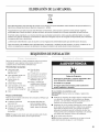
EXIGENCESD'INSTALLATION
Rassembter les outils et pi_ces necessaires avant de commencer
I'instattation. Life et respecter les instructions d'instattation
fournies avec chacun des outits de cette liste.
OutiHage n_cessaire
[] Cte h tube de 200 mm (8") [] Couteau utititaire
ou 250 mm (10") [] Brides de fixation
[] Cle h molette de 200 mm [] Compose d'etancheite des
(8") ou 250 mm (10") raccords fitetes - r_sistant
[] Tournevis h lame plate au propane
[] Tournevis Phillips [] Pistotet h calfeutrage et
[] Cle & molette avec compose de catfeutrage
ouverture jusqu'h 25 mm (pour I'instatlation d'un
(1") ou cte & douille nouveau circuit
hexagonale d'evacuation)
[] Niveau [] Pince
[] Cle h douilte de 8 mm [] Couteau & mastic
(5/16") h lame rigide
Pi_ces fournies
Retirer le sac de pi6ces du tambour du s_che-linge. Verifier la
presence de toutes les pi_ces.
[] Patin (4)
[] Pied du s6che-linge (4)
[] Mod_tes PD : Came pour
le verrouillage de la porte
de service
ModUles PN : Bottler du
lecteur de carte, faisceau
de c&btage du lecteur de
carte, visserie
REMARQUE : Le schema de circuits de ce seche-linge se trouve
l'interieur du panneau inferieur avant, dans lesfiches techniques.
19

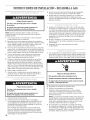
Risque d'explosion
Garder les mati_res et les vapeurs inflammables, telle
que I'essence, loin de la s_cheuse.
Ne pas installer dans un garage.
Le non-respect de ces instructions peut causer
un d_c_s, une explosion ou un incendie.
Pour I'installation d'un s_che-linge & gaz :
IMPORTANT : Respecter les dispositions de tousles codes et
r_)glements en vigueur.
[] Determiner les exigences des codes : Certains codes limitent
ou prohibent l'instaltation d'un s_)che-tinge dans un garage,
un placard, ou une chambre _ coucher. Consulter I'inspecteur
local des b_timents.
[] Veilter _ ce que les bords inferieurs de la caisse ainsi que
I'arri_)reet les c6tes inferieurs du s_)che-linge soient exempts
d'obstructions, afin de permettre le passage adequat de I'air
de combustion. Voir ta section "Instructions d'instattation dans
un placard ou un encastrement" pour I'espace de
degagement minimal.
[] Ne pas installer sur un tapis.
NOTE : Le s_)che-linge ne dolt pas _tre installe en un endroit oC_il
serait expose _ de I'eau ou aux intemperies.
instructions pour I'installation darts un placard ou
un encastrement
Ce s_che-linge peut _tre installe dans un placard ou un
encastrement. Ce seche-linge ne dolt pas _tre instatte derrri_re
une porte verrouillabte, coulissante, ou une porte avec charni_re
du c6te oppose de I'emptacement de cetle du s_che-linge.
Les distances de separation sont exprimees en mitlimetre;
il s'agit des distances minimales. II est utile de pr_voir des
distances de separation superieures pour faciliter l'instatlation
et les travaux d'entretien, ou si ceci est exige par les codes et
r_glements Iocaux.
Si la porte du placard est instattee, on dolt respecter la taitle
minimate des ouvertures d'entr_e d'air au sommet et en bas. On
peut utitiser une porte &jalousies offrant une surface de passage
d'air equivalente.
Le circuit d'evacuation du seche-linge dolt _tre retie & l'exterieur.
Aucun autre appareil utilisant un combustible ne dolt _tre instalte
dans le m_me placard.
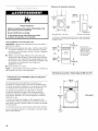
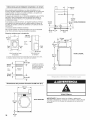
Distances de s_paration minimales
381 mm
(15")
o o
EZZ:]E:Z::_-o°
0 rnm _ 0 rnm
(o") "---_ (o")
Encastrement, vue avant
356 mm
(14") max
Portedu
placard
J
(1
....... Omm
(0")
_1 1_25mr. I1")
Placard, vue laterale
On dolt pr_voir un espacement additionnel pour tenir compte _ventuellement
des moulures du mur, de la porte et du plancher, ou si le circuit d'_vacuation
comporte un coude.
Portedu
placard
(48in._)
vue
avant 0
(24in._)
* Taille minimale de
I'ouverture pour la porte
du placard. On peut
utiliser une porte
claire-vole offrant une
surface de passage
d'air _quivalente.
i
76 mm (3")
Dimensions du produit - S_che-linge de 686 mm (27")
965 mm
686 mm
(27")
I
t
VUE AVANT
25 mm
(1")
2O
La page est en cours de chargement...
La page est en cours de chargement...
La page est en cours de chargement...
La page est en cours de chargement...
La page est en cours de chargement...
La page est en cours de chargement...
La page est en cours de chargement...
La page est en cours de chargement...
La page est en cours de chargement...
La page est en cours de chargement...
La page est en cours de chargement...
La page est en cours de chargement...
La page est en cours de chargement...
La page est en cours de chargement...
La page est en cours de chargement...
La page est en cours de chargement...
La page est en cours de chargement...
La page est en cours de chargement...
La page est en cours de chargement...
La page est en cours de chargement...
La page est en cours de chargement...
La page est en cours de chargement...
La page est en cours de chargement...
La page est en cours de chargement...
La page est en cours de chargement...
La page est en cours de chargement...
La page est en cours de chargement...
La page est en cours de chargement...
La page est en cours de chargement...
La page est en cours de chargement...
La page est en cours de chargement...
La page est en cours de chargement...
La page est en cours de chargement...
La page est en cours de chargement...
La page est en cours de chargement...
La page est en cours de chargement...
La page est en cours de chargement...
La page est en cours de chargement...
La page est en cours de chargement...
La page est en cours de chargement...
La page est en cours de chargement...
La page est en cours de chargement...
La page est en cours de chargement...
La page est en cours de chargement...
-
 1
1
-
 2
2
-
 3
3
-
 4
4
-
 5
5
-
 6
6
-
 7
7
-
 8
8
-
 9
9
-
 10
10
-
 11
11
-
 12
12
-
 13
13
-
 14
14
-
 15
15
-
 16
16
-
 17
17
-
 18
18
-
 19
19
-
 20
20
-
 21
21
-
 22
22
-
 23
23
-
 24
24
-
 25
25
-
 26
26
-
 27
27
-
 28
28
-
 29
29
-
 30
30
-
 31
31
-
 32
32
-
 33
33
-
 34
34
-
 35
35
-
 36
36
-
 37
37
-
 38
38
-
 39
39
-
 40
40
-
 41
41
-
 42
42
-
 43
43
-
 44
44
-
 45
45
-
 46
46
-
 47
47
-
 48
48
-
 49
49
-
 50
50
-
 51
51
-
 52
52
-
 53
53
-
 54
54
-
 55
55
-
 56
56
-
 57
57
-
 58
58
-
 59
59
-
 60
60
-
 61
61
-
 62
62
-
 63
63
-
 64
64


Maytag MDG25PD Installation Instructions Manual
- Catégorie
- Sèche-linge électriques
- Taper
- Installation Instructions Manual
- Ce manuel convient également à
dans d''autres langues
- italiano: Maytag MDG25PD
- English: Maytag MDG25PD
- español: Maytag MDG25PD
Documents connexes
-
Maytag MDE17CS Guide d'installation
-
-
-
-
-
-
-
-
-
Maytag MLG20PDBGW1 Guide d'installation