Nuvo Cocerto NV-I8GXS Manuel utilisateur
- Catégorie
- Équipement musical supplémentaire
- Taper
- Manuel utilisateur


ENGLISH
Danger
Exposure to extremely high noise levels may cause a permanent
hearing loss. Individuals vary considerably to noise induced hearing
loss but nearly everyone will lose some hearing if exposed to sufficiently
intense noise for a sufficient time. The U.S. Government's
Occupational Safety and Health Administration (OSHA) has specified
the following permissible noise level exposures:
According to OSHA, any exposure in the above permissible limits could
result in some hearing loss. Ear plugs or protectors in the ear canal or over
the ears must be worn when operating this amplification system in order to
prevent a permanent hearing loss. If exposure in excess of the limits as
put forth above, to insure against potentially harmful exposure to high
sound pressure levels, it is recommended that all persons exposed to
equipment capable of inducing high sound pressure levels, such as this
amplification system, be protected by hearing protectors while this unit is in
operation.
DURATION PER DAY (HOURS) 8 6 4 3 2 1
SOUND LEVEL (dB) 90 93 95 97 100 103
THIS SYMBOL IS INTENDED TO ALERT THE USER TO THE PRESENCE
OF NON-INSULATED "DANGEROUS VOLTAGE" WITHIN THE
PRODUCT'S ENCLOSURE THAT MAY BE OF SUFFICIENT MAGNITUDE
TO CONSTITUTE A RISK OF ELECTRIC SHOCK TO PERSONS.
THIS SYMBOL IS INTENDED TO ALERT THE USER TO THE PRESENCE
OF IMPORTANT OPERATING AND MAINTENANCE (SERVICING)
INSTRUCTIONS IN THE LITERATURE ACCOMPANYING THE UNIT.
1. Read all safety and operating instructions before using this
product.
2. All safety and operating instructions should be kept for future
reference.
3. Read and understand all warnings listed on the operating
instructions.
4 . Follow all operating instructions to operate this product.
5. This product should not be used near water, i.e. bathtub, sink,
swimming pool, wet basement, etc.
6. Only use dry cloth to clean this product.
7. Do not block any ventilation openings, It should not be placed flat
against a wall or placed in a built-in enclosure that will impede the
flow of cooling air.
8. Do not install this product near any heat sources ; such as,
radiators, heat registers, stove or other apparatus (including heat
producing amplifiers) that produce heat.
9. Do not defeat the safety purpose of the polarized or grounding-
type plug. A polarized plug has two blades with one wider than the
other. A grounding-type plug has two blades and a third grounding
prong. The wide blade or the third prong are provided for your
safety. If the provided plug does not fit into your outlet, consult an
electrician for replacement of the obsolete outlet.
10. Protect the power cord being walked on or pinched, particularly at
plugs, convenience receptacles and the point where they exit
from the apparatus. Do not break the ground pin of the power
supply cord.
11 . Only use attachments specified by the manufacturer.
12. Use only with the cart, stand, tripod, bracket, or table specified by
the manufacturer or sold with the apparatus. When a cart is used,
use caution when moving cart/apparatus combination to avoid
injury from tip-over.
13. Unplug this apparatus during lightning storms or when unused for
long periods of time.
14. Care should be taken so that objects do not fall and liquids are
not spilled into the unit through the ventilation ports or any other
openings.
15. Refer all servicing to qualified service personnel. Servicing is
required when the apparatus has been damaged in any way;
such as, power-supply cord or plug is damaged, liquid has been
spilled or objects have fallen into the apparatus, the apparatus
has been exposed to rain or moisture, does not operate normally
or has been dropped.
16. WARNING: To reduce the risk of fire or electric shock, do not
expose this apparatus to rain or moisture.
IMPORTANT SAFETY INSTRUCTIONS
RISK OF ELECTRIC SHOCK
DO NOT OPEN
CAUTION: TO REDUCE THE RISK OF ELECTRIC SHOCK, DO
NOT REMOVE CHASSIS. NO USER-SERVICEABLE
PARTS INSIDE. REFER SERVICING TO QUALIFIED
SERVICE PERSONNEL.
AVIS: RISQUE DE CHOC ELECTRIQUE-NE PAS OUVRIR.
CAUTION
APPARATUS SHALL NOT BE EXPOSED TO DRIPPING OR SPLASHING
AND THAT NO OBJECTS FILLED WITH LIQUIDS, SUCH AS VASES,
SHALL BE PLACED ON THE APPARATUS.
1

2
FRENCH
DURE EN HEURES PAR JOUR 8 6 4 3 2 1
INIVEAU SONORE CONTINU EN dB 90 93 95 97 100 103
Danger
L‘exposition a des niveaux eleves de bruit peut provoquer une perte
permanente de l’audition, Chaque organisme humain reagit
differemment quant a la perte de l’audition, mais quasiment tout le
monde subit une diminution de I’acuite auditive lors d’une exposition
suffisamment longue au bruit intense. Les autorites competentes en
reglementation de bruit ont defini les expositions tolerees aux niveaux
de bruits:
Selon les autorites, toute exposition dans les limites citees ci-dessus,
peuvent provoquer certaines pertes d’audition. Des bouchons ou
protections dans l’appareil auditif ou sur l’oreille doivent etre portes lors
de l’utilisation de ce systeme d’amplification afin de prevenir le risque
de perte permanente de l’audition, Dans le cas d’expositions
superieures aux limites precitees il est recommande, afin de se
premunir contre les expositions aux pressions acoustiquese I evees
potentielIement dangeure u ses, aux personnes exposees aux
equipements capables de delivrer de telles puissances, tels ce
systeme d’amplification en fonctionnement, de proteger l’appareil
auditif.
ATTENTION: AFIN DE LlMlTER LE RISQUE DE CHO ELECTR/QUE, NE
PAS ENLEVER LE CHASSIS. NE CONTIENT PAS DE
PIECES POUVANT ETRE REPAREE PAR L’UTILISATEUR.
CONFER LE SERVICE APRES-VENTE AUX
REPARATEURS
ATTENTION
RISQUE DE CHOC ELECTRIQUE
NE PAS OUVRIR.
CE SYMBOLE A POUR BUT D'AVERTIR L'UTILISATEUR DE LA PRESENCE
DE VOLTAGE DANGEREUX NON-ISOLE A L'INTERIEUR DE CE PRODUIT
QUI PEUT ETRE DE PUISSANCE SUFFISAMMENT IMPORTANTE POUR
PROVOQUER UN CHOC ELECTRIQUE AUX PERSONNES.
CE SYMBOLE A POUR BUT D'AVERTIR L'UTILISATEUR DE LA PRESENCE
D'INSTRUCTIONS D'UTILISATION ET DE MAINTENANCE DANS LES
DOCUMENTS FOURNIS AVEC CE PRODUIT.
IMPORTANTES INSTRUCTIONS DE SECURITE
1. Lire avec attention toutes les recommandations et précautions
d'emploi avant d'utiliser ce produit.
2. Toutes les recommandations et précautions d'emploi doivent être
conservées afin de pouvoir s'y reporter si nécessaire.
3. Lire et comprendre tous les avertissements énumérés dans les
précautions d'emploi.
4. Suivre toutes les précautions d'emploi pour utiliser ce produit.
5. Ce produit ne doit pas être utilisé près d'eau, comme par exemple
baignoires, éviers, piscine, sous-sol humides ... Etc.
6. Utiliser exclusivement un chiffon sec pour nettoyer ce produit.
7. Ne bloquér aucune ouverture de ventilation. Ne pas placer le
produit tout contre un mur ou dans une enceinte fernée, cela
gênerait le flux d'air nécessaire au refroidissement.
8. Ne pas placer le produit près de toute source de chaeur telle que
radiateurs, arrivées d'air chaud, fourneaux ou autres appareils
générant de la chaleur (incluant les amplificateurs producteurs
de chaleur) .
9. Ne pas négliger la sécurité que procure un branchement polarisé
ou avec raccordement à la terre, Un branchement polarisé
comprend deux fiches dont l'une est plus large que l'autre. Un
branchement à la terre comprend deux fiches plus une troisième
reliée à la terre. Si la fiche secteur fournie ne s'insert pas dans
votre prise de courant. consulter un 'électricien afin de remplacer
votre prise obsolète.
10. Protéger le cordon d'alimentation de tout écrasement ou
pincement, particulièrement au niveau des fiches, des
réceptacles utilisés et à l'endroit de sortie de l'appareil. Ne pas
casser la fiche de terre du cordon d'alimentation.
11. Utiliser uniquement les accessoires spécifiés par le constructeur.
12. Utiliser uniquement avec le chariot de transport, le support, le
trépied, la console ou la table spécifiés par le constructeur ou
vendus avec l'appareil. Lors de l'utilisation d'un chariot, bouger
avec précaution l'ensemble chariotlappareil afin d'éviter les
dommages d'un renversement.
13 Débrancher cet appareil lors d'orages ou s'il n'est pas utilisé
pendant une longue période.
14. Des précautions doivent être prises afin qu'aucun objet ne tombe
et qu'aucun liquide ne se répande à l'intérieur de l'appareil par
les orifics de ventilation ou n'importe quelle autre ouverture.
15. Pour toutes interventions techniques s'adresser à un technicien
qualifié.L'intervention technique est nécessaire lorsque l'appareil
a été endommagé de n'importe quelle façon, comme par
exemple si le cordon secteur ou sa fiche sont détériorés,si du
liquide a coulé ou si des objets sont tombés à l'intérieur de
l'apparei1,si l'appareil a été exposé à la pluie ou à l'humidité, s'il
ne fonctionne pas normalement ou s'il est tombé.
16. ATTENTI0N:Pour réduire le risque d'incendie ou de choc
electrique ne pas exposer l'appareil à la pluie ou à l'humidité.
AFIN DE REDUIRE LES RISQUÉ D'INCENDIE ET DE DECHARGE
ELECTRIQUE, NE PAS EXPOSER CET APPAREIL A LA PLUIE OU A
L'HUMIDITE.

3
Introduction
Congratulations on the purchase of your NuVo System. The Grand Concerto System is truly NuVo's newest masterpiece. The Grand
Concerto's state-of-the-art interface and NuVoNet communication with the Grand Concerto Suite of audio components offer the
best, most affordable whole-home audio system available.
Grand Concerto delivers 80 startlingly clear watts of sound to up to 16 independent zones simultaneously. NuVo's Generation D,
class D amplification uses the newest technology in digital amplification, which requires less power and is able to operate at peak
capacity while generating very little heat.
The Grand Concerto Control Pad interface offers the elegance and control of an expensive touch panel at a keypad price. The new
OLED (organic light emitting diode) display allows up to eight lines of text for easily scrolling through music titles and menu
selections. Capacitive touch controls provide immediate access to the audio sources without external rubber buttons. The result is
a single piece of polycarbonate plastic that provides ultra-responsive water-resistant access to your music from any room of the
house.,
The EZ IR Learning Station makes system setup easy and intuitive. Creating customized audio control is as easy as typing in a
Windows template. The Learning Station will allow IR commands for the source equipment to be stored in files for future use,
making programming the system as simple as the push of a button.
This installation manual outlines the installation and setup of your new Grand Concerto System. We recommend that you read this
manual prior to installing your system. Proper installation and setup will insure years of audio enjoyment.

4
R
OUTPUT POWER
OUTPUT POWER
20W/6OHM X2
20W/6OHM X2
SYS ON
EXT. MUTE
L
R
L
R
L
R
VARI ABL E
OUTPUT
FIXED
OUTPUT
SUM1
303 3118
C
US
CON FORMS T O
UL ST D.65 00
CER TIFI ED TO
CAN /CSA STD .E600 65
NuVo Tec hnolo gies Cin cinna ti Ohio U SA
FUS E:T5 A
120 V 60Hz 50 0W
MODE L NV-I8D M
SIX SO URCE EI GHT ZON E
AUDI O DISTR IBUTI ON SYST EM
www. nuvot echno logie s.com
OUTPUT POWER
OUTPUT POWER
OUTPUT POWER
20W/6OHM X2
20W/6OHM X2
20W/6OHM X2
TIP=L
RING=R
VARI ABL E
OUTPUT
FIXED
OUTPUT
TIP=L
RING=R
VARI ABL E
OUTPUT
FIXED
OUTPUT
TIP=L
RING=R
VARI ABL E
OUTPUT
FIXED
OUTPUT
TIP=L
RING=R
VARI ABL E
OUTPUT
FIXED
OUTPUT
TIP=L
RING=R
VARI ABL E
OUTPUT
VARI ABL E
OUTPUT
FIXED
OUTPUT
FIXED
OUTPUT
TIP=L
RING=R
TIP=L
RING=R
1 2 3 4 5
6
1 2 3 4 5
6
2 3
4
1 2 3
RS-23 2
CONNEC T TO
NV-I8X
USE NV-SL C1
CABLE
CONNEC T TO
NV-I8X
USE NV-SL C1
CABLE
CONNEC T TO
NV-I8EZ P1
USE NV-NC 1
CABLE
USE CNLY WITH 250V FUSE
4
5
6
SUM2
5 6 7
8
OUTPUT POWER
20W/6OHM X2
ZONE 6ZONE 6
ZONE 7&8
SYSTEM
ZONE TRIG GER OUTPUTS
SOURCE LI NK
SOURCE IN PUTS
ZONE 1
NETWORK
EMITTER O UTPUTS DIGITAL LINK
ZONE 3
ZONE 4
ZONE 5
ZONE 2
PROGRAM
6
4
5
3
1
2
SOURC E STATU S INPUTS
1
2
3
4
5
6
7
8
9
10
11
12
14
13
1
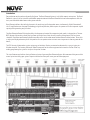
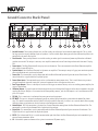
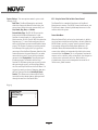
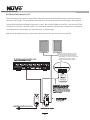
Grand Concerto Back Panel
1. Variable Lineouts: These preamp lineouts are used for sending an audio signal to an external power amplifier. This is useful
for large areas that require additional pairs of speakers. Use the variable output when you want the additional amplifier to be
controlled by the zone's Display Pad.
2. Fixed Lineouts: These preamp lineouts are used for sending an audio signal to an external power amplifier when additional
speakers are needed. This output is constant, so an amplifier connected to it will not change volume with that zone's Display
Pad.
3. Source Inputs: The Grand Concerto will accept up to six audio sources. These are connected to the Grand Concerto amplifier
with standard stereo RCA cables.
4. Speaker Output: Six of the Grand Concerto's eight zones are amplified. These outputs accept 16-gage, two-conductor speaker
wire and provide 40 watts per channel of power.
5. Source Link: This connection is used in conjunction with the Grand Concerto Expander System to create 16 total zones. The
source link cable is supplied with the Expander System.
6. Source Status Inputs: These optional inputs can be used to monitor source power status. This is useful when using a macro
string of commands to prevent turning off a piece of equipment that is already on and vice versa.
7. Zone Trigger Outputs: These 12-volt outputs can be used to trigger an external device, such as an auxiliary power amplifier, for
use in a specific zone.
8. IR Emitter Outputs: IR signals received from the keypads are passed through the IR outputs to the source equipment using the
supplied IR emitters. Outputs 1-6 are routed to the corresponding sources, and the SUM outputs 1 and 2 are common and will
pass all IR signals.
9. SYS. ON: This is a constant 12-volt output for turning on external equipment.
10. EXT. MUTE: This input is designed to temporarily mute any audio playing through the system when the doorbell or phone
rings. This works in conjunction with the NuVo NV-MI1 mute interface accessory. It also acts as a mute for whole-house paging
through a phone system when set for this function in the Configurator software.
11. Network Input: This RJ45 connection is the input for all zone information coming from the Grand Concerto Control Pads. The
connection is made using the Network Cable supplied with the package.
12. Digital Link: This connection is used in conjunction with the Grand Concerto Expander System to create 16 total zones. The
Digital Link cable is supplied with the Expander System.
13. RS232: The bidirectional RS232 is a serial communication port that allows the Grand Concerto System to be controlled by an
external home automation device.
14. AC: A detachable power cord connects the system to an external AC power supply.

5
MENU
OK
Modern Rock
Drift-Follow The Day
Living For
AM/FM
3:09 pm
1
2
3
4
5
6
7
8
9
10
11
12
13
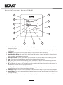
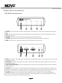
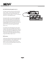
Grand Concerto Control Pad
1. Source indicator: This indicates the current audio source playing in that zone. Source names can be customized in the
Configurator software.
2. Cover plate: Each Control Pad comes with white, ivory, almond, and black trim plates that attach magnetically to the face
of the keypad.
3. OLED Display: The organic light emitting diode display is a highly functional multi-line display.
4. Now Playing/Menu Display: This portion of the display serves two functions. In normal operation, it indicates the artist,
station, metadata, and other source information.
5. Volume Level Indicator: This bar graph indicates the audio volume level when the Control Pad is in normal play mode.
6. Power: This button turns the local zone on and off and turns all zones off simultaneously.
7. Menu: Menu serves as access to music browsing, presets, and favorites, as well as specific zone-setting parameters.
8. Play/ Pause: This button serves as a general stop and start button for each of the sources.
9. OK: The OK button also serves a dual function. In normal play mode, it scrolls through the available audio sources. In
menu mode, it is used to select the highlighted menu item.
10. Arrow Up and Down: These arrows have a dual function. In normal play mode, they control volume level up and down. In
menu mode, they scroll up and down through menu selections.
11. IR Receiver: The Control Pad has a built-in IR receiver for complete wireless control of all the audio source equipment.
12. Forward/Reverse: This is an IR programmable button for simple source transport. Typically it would track forward or back
or tune up and down.
13. Time: A feature of the Grand Concerto System is the ability to display the current time on each of the Control Pads.

HOLD
ALL OFF
Concerto
NV-I8GRC1
REMOTE CONTROL
FAVORITES
VOLUME
1
2
3
4
5
6
7
8
9
11
10
12
SOURCE/OK
PWR
MUTE
SLEEP
DISP
MENU
G2
G1
F1 F2
F3 F4
1
2
3
4
5
6
7
8
9
10
11
12
13
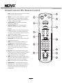
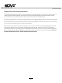
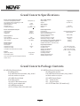
Grand Concerto RC1 Remote Control
6
1. Power: Each zone can be turn on and off, or all zones
can be turned off with this button.
2. Volume: This actually serves to functions. In normal
operation mode, it is a volume control, but when
you are using the menu features of the Control Pad,
it allows scrolling up and down.
3. Function Buttons: These buttons allow for one-
button macro commands.
4. Forward and Reverse: These IR programmable
buttons are designed for forward and reverse
functions.
5. Favorites: A function of the Grand Concerto System
is the ability to access user defined favorites for
easy access. The first twelve are directly accessible
using the RC1 Favorites buttons.
6. DISP: This button allows access to the Display dim
menu available at each Control Pad.
7. Function LED: This LED (Light Emitting Diode) lights
to indicate a button push.
8. MUTE: The RC1 remote provides a discrete mute
function to quickly silence the zone's output.
9. SOURCE/OK: This is another dual function button. In
normal playback mode it scrolls through the
sources, or in menu mode it selects a highlighted
menu choice.
10. Play/Pause: This IR programmable button toggles
between the play and pause functions of the chosen
source. When using the T2 Tuners, this button
toggles through the Tuners receive modes.
11. MENU: This button enters the menu features of the
Control Pad. One in Menu mode the Volume up and
down buttons scroll through the menu choices.
12. Sleep: This allows access to the sleep timer mode.
13. Dynamic Groups: A unique function of the Grand
Concerto System is the ability to create temporary
zone groups using the G1 and G2 buttons. This is
useful if you wish to listen to a single source in
multiple zones.

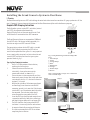
Installing the Grand Concerto System in Your Home
I. Prewire
The Grand Concerto System uses CAT5 cable for keypad control and either two or four-conductor 16-gauge speaker wire. All the
wire is “homerun” from each zone to the location of the Grand Concerto amplifier and Audio Source equipment.
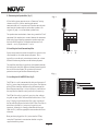
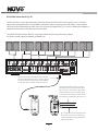
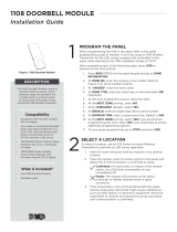
Complete CAT5 Crimping Instructions
The NuVo audio systems require CAT5, unshielded, twisted
pair (UTP), for communication between the
keypads/Display Pads and the main amplifier unit. Each
end of the wire is terminated with an RJ45 connector.
The Grand Concerto System can accommodate 2,000 total
feet of CAT5 cable. For the most reliable operation, it is
best that no single run of CAT5 exceeds 250 feet.
The correct wiring scheme for the CAT5 cable is standard
EIA/TIA 568A. Properly terminating the CAT5 cable is
crucial for the operation of the system. It is very important
to use a good quality crimp tool, and test each end to end
run with a CAT5 wire tester to insure that your system
operates flawlessly, fig.1.
Step-by-Step Crimping Instructions:
1. Strip a 2 to 3 inch portion of the insulation,
exposing the 4 twisted pairs.
2. Untwist the wires and fan them out
individually. Arrange the wires into the
correct color scheme as shown in Fig. 1.
3. Flatten the wires in their correct order, and trim
them evenly across the top. Most crimp tools have
a wire trimmer built-in. It is best to trim the wires
to about ½” in length.
4. While holding the wires flat between your thumb
and forefinger, insert the wires into the RJ45
connector, so each is in its own slot. Push the wire
into the RJ45, so all 8 conductors touch the end of
the connector. The insulation jacket should
extend beyond the crimp point of the RJ45.
5. Insert the RJ45 into the crimp tool receptacle and
squeeze the tool firmly. Note that a ratchet type
tool should tighten down until it no longer clicks.
6. The RJ45 should be firmly crimped to the CAT5
insulation. It is necessary that the color scheme
be repeated identically on each end of the wire.
7. Test each termination with a CAT5 Tester before
completing the installation.
Fig. 1: EIA 568A wiring scheme for CAT5 Cable
Pin #
1. Green Stripe
2. Green
3. Orange Stripe
4. Blue
5. Blue Stripe
6. Orange
7. Brown Stripe
8. Brown
Note: Colors listed as “stripe” are a white wire
with a colored stripe.
Step 1 Step 2 Step 3
Step 4
Step 5 Step 6
1 2 3 4 5 6 7 8
Top view with
tab down.
Wires insert from
this end.
Pair 2
Pair 3
Pair 4
Pair 1
IR
Ac
t
i
ve
G
r
ou
nd
Cont
r
o
l
Da
t
a
B
u
s
-
C
on
t
r
o
l
D
a
t
a B
u
s
+
IR
Dat
a
Gr
o
u
n
d
+
1
2
V
P
o
w
e
r
G
r
ou
n
d
7

-
-
+
+
LEFT
RIGHT
LEFT
RIGHT
8
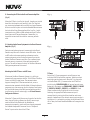
II. Terminating the Speaker Wire (fig. 2)
All the NuVo systems operate across a “homerun”-wiring
scheme using Cat-5 for the zone keypad control
communication, and a separate run of speaker wire for each
zone from the speaker outputs to the zone speakers. We
suggest 16-gage 2- or 4-conductor speaker wires.
The speaker wire termination is done using a modular “Euro”
connector. Each conductor is screwed down to the connector
block and plugged into the appropriate speaker output on
the back of the amplifier. The proper termination is Left
channel: – and +; Right channel: – and +.
Fig. 2
III. Installing the Grand Concerto Amplifier
System setup works best when the amplifier is placed in the
same location as the audio source equipment. This is
typically in an audio rack, entertainment center, or a closet
dedicated to housing the home audio/video equipment.
The amplifier should be plugged in and the power button on
the front panel should be depressed before proceeding with
the rest of the installation. This activates the internal
protective circuitry of the Grand Concerto System.
IV. Installing the NV-I8GEZP EZ Port (fig.3)
The EZ Port is a multi-connection hub designed to accept all
the Cat-5 wires from the keypads in the system. The location
of the EZ Port should be determined by the location of the
Grand Concerto amplifier. It is best to place in a wall behind
the amplifier that would be easily accessible if necessary.
The EZ Port fits easily in any dual-gang-size, low-voltage
ring with an open back. These are often referred to as “mud
rings.” Simply plug the terminated Cat-5 wires into any of
the 20 available jacks on the back of the EZ Port. The order in
which the individual Cat-5 wires are plugged in is not
important, although it is strongly recommended that you
label the Cat-5 with the appropriate zone number for future
reference.
Once you have plugged the Cat-5 wires into the EZ Port,
screw the EZ port into its construction bracket using the
supplied mounting screws.
Fig. 3

Device 1
Connect to
NV-I8GM
Concerto EZ Port
Model NV-I8GEZP
www.nuvotechnologies.com
NuVoTechnologies LLCHebron, Kentucky USA
Device 2 Device 3
Device 4 Device 5 Device 6
R
SYS ON
EXT. MUTE
SUM1
3033118
C
US
CONFORMS TO
UL STD.6500
CERTIFIED TO
CAN/CSASTD.E60065
NuVoTechnologies CincinnatiOhio USA
FUSE:T5A
120V 60Hz 500W
MODEL NV-I8DM
SIXSOURCE EIGHT ZONE
AUDIODISTRIBUTION SYSTEM
www.nuvotechnologies.com
VARIABLE
OUTPUT
FIXED
OUTPUT
TIP=L
RING=R
RS-232
CONNECT TO
NV-I8X
USE NV-SLC1
CABLE
CONNECT TO
NV-I8EZP1
USE NV-NC1
CABLE
USE CNLYWITH 250V FUSE
SUM2
OUTPUT POWER
20W/6OHM X2
ZONE 7&8
SYSTEM
NETWORK DIGITAL LINK
PROGRAM
SOURCE LINK
SOURCE INPUTS
ZONE 1
ZONE 3
ZONE 2
CONNECT TO
NV-I8X
USE NV-SLC1
CABLE
12 34 5
6
12 34 5
6
ZONE 1
ZONE 3
ZONE 2
OUTPUT POWER
OUTPUT POWER
OUTPUT POWER
20W/6OHM X2
20W/6OHM X2
20W/6OHM X2
VARIABLE
OUTPUT
VARIABLE
OUTPUT
VARIABLE
OUTPUT
FIXED
OUTPUT
FIXED
OUTPUT
FIXED
OUTPUT
TIP=L
RING=R
TIP=L
RING=R
TIP=L
RING=R
L
AUDIO OUT
AUX IN
R
TRIGGER
ON=+12V
AUDIO
OUTPUT
TUNER BANTENNA INPUT
IN
USE ONLY NuVo
NV-T2PAS
POWERED ANTENNA SYSTEM
9
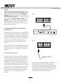
V. Connecting the EZ Port to the Grand Concerto Amplifier
(fig. 4)
When the EZ Port is installed in the wall, the only part visible
should be the faceplate and four RJ45 jacks. The supplied
pre-terminated network cable can then be plugged into one
of the six available jacks and into the Network connection on
the back of the Grand Concerto Amplifier. Any Cat-5 cable
terminated using 568A or 568B network wiring will suffice
should you need a longer connection. Remember, it is
important to terminate the cable the same way on both
ends.
Fig. 4
VI. Attaching Audio Source Equipment to the Grand Concerto
Amplifier (fig. 5)
Each piece of audio equipment is connected to the Grand
Concerto amplifier with standard stereo RCA cables. Attach
an RCA cable to the corresponding audio output on the
source equipment and to the desired source input on the
back of the Grand Concerto amplifier. The numbered input
for each source is important in the configuration of the
system. This will be covered in detail in the Grand Concerto
Configurator portion of this manual.
Fig. 5
Attaching the NuVo T2 Tuners and M3 Server
X. Grand Concerto
Configurator Software.
A feature of the Grand Concerto System is its ability to
automatically communicate with the T2 AM/FM and Satellite
Tuners and the M3 Audio Server. The communication
happens through the EZ Port connection hub, across a
communication protocol called NuVoNet. Although software
programming is not necessary for this function, configuring
the installation through the Configurator Software prior to
installation has distinct advantages, see
When the T2 Tuners or M3 Server are plugged in for the first
time, they will display a prompt to select a source input
number for the Grand Concerto. For NuVoNet to
communicate properly, you should have already connected
the NuVoNet components to one of the six “Peripheral
Device” inputs on the face of the EZ Port.
T2 Tuners
OPERATING MODE
STAND ALONE, SOURCE 6, SOURCE
5, SOURCE 4, SOURCE 3, SOURCE 2, SOURCE 1
Each of the T2 Tuner components actually houses two
individual AM/FM or Satellite receivers, which have their
own display on the front panel. Once the T2 is plugged in
and the NuVoNet CAT-5 is connected to the EZ Port and
initial display, will appear for each tuner.
Below this, the choices are
and . Stand
Alone is automatically highlighted at initial startup.
Selecting the appropriate Concerto source input is
accomplished by turning the Select knob for each tuner
counter-clockwise until the desired source input number is
highlighted. It is selected by pushing the Select knob. Once
this is done, the Grand Concerto NuVoNet will recognize that
source.

SYSTE M
ZONE TR IGGER O UTPUT S
EMITT ER OUTP UTS
SYS ON
EXT. MUTE
SUM1
1 3
5
7
8
1
3 5
2
4
6
SUM2
2 4
6
6
dISC
COMPACT
2 3
4
5 6 7
8
ZONE TRIGG ER OUTP UTS
ZONE 4
ZONE 5
6
4
5
3
1
1
2
SOURC E STATUS INP UTS
Current sensor attaches to the
AC power cord of the source
equipment.
10
M3 Server
At initial startup, the front panel display will prompt with
OUTPUT 1: PRESS OK TO SELECT NUVONET SOURCE. When OK is
selected, the top line of the display will read OPERATING
MODE OUT 1. Below this the three available lines will display
STANDALONE, SOURCE 1, SOURCE 2 . . . as you scroll using the
down arrow button, SOURCE 3, SOURCE 4, SOURCE 5, and
SOURCE 6 will appear. Highlight the appropriate choice and
press OK to select. This will set the first channel music
output. You will then be prompted to repeat for these steps
for the remaining two channels.
VII. Connecting the IR Emitters for Third-Party Source
Components (fig. 6)
IR commands for the source equipment are transferred from
the Grand Concerto amplifier to the source equipment using
the mini IR mouse emitters. Six of these are supplied with
your Grand Concerto System. The emitter is plugged into the
corresponding source IR output on the Grand Concerto and
then placed over the IR receiver window on the source
component. The IR outputs are individually routed to
sources 1-6.
The two SUM outputs will flash any IR command that is sent
from any of the zones. This is most commonly used with an
IR blaster designed to flash IR commands to a variety of
components.
Fig. 6
VIII. Source Status Inputs (fig. 7)
The source status inputs can be very useful for monitoring
the power status of your audio sources. Some equipment
uses “toggling commands” for powering on and off (that is,
the commands for on and off are not separate, discrete
commands). This situation is typically confusing when using
a single button to initiate to a piece of source equipment a
string of commands that includes power on. With “toggling”
equipment, if the unit is already on, moving the button will
inadvertently turn it off. The source status inputs give the
Grand Concerto System the ability to sense that the source
equipment is on so it can automatically bypass that
command.
Fig. 7
Using these inputs requires an AC power-sensing module.
These are readily available from electronic accessory
manufacturers and typically attach to the AC power cord of
the desired source equipment. The connection at the back of
the Grand Concerto is a mono 1/8” jack. Once this is in place,
the Grand Concerto System will sense the amount of AC
current being drawn by the source equipment.

11
IX. Expanding Grand Concerto to 16 Zones (fig. 8)
Eight additional listening zones can be added to the Grand
Concerto System using the Grand Concerto Expander
package. The expansion is easily done using the Source Link
and Digital Link multi-pin outputs on the Grand Concerto
main amplifier (NV-I8DMS).
The necessary cables for this are supplied with the Expander
package. No other connections are necessary except the AC
power cord and the additional speaker terminations. The
additional Cat-5 wires for the zones 9-16 plug into the
Grand Concerto main EZ Port.
Fig. 8
X. Using the Grand Concerto Configurator Software
The following section requires the NV-I8DLS IR Learning
Station and Configurator Software. This is available as a
package from NuVo Technologies or any Authorized NuVo
Distributor. The Configurator software is a PC program
designed to run with Windows 2000, XP, and XP Pro.
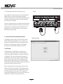
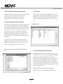
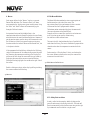
1. Main Startup
The Configurator is a tabbed Wizard-style interface
designed to sequentially walk the installer through the
system setup. When the program is launched, the Start tab
is highlighted. This gives three choices for beginning a
configuration. You can create a new file, open an existing
file, or retrieve an existing file from a configured Grand
Concerto System. Once configured, the finished program
loaded into the Grand Concerto main amplifier can always be
retrieved via the RS232 port and edited.
Once a configuration file has been opened, you can then
click on the next button to continue. The Configurator will
not let you continue beyond Start without either creating a
new file or opening an existing file. It will also prevent
moving forward through any of the tabs until the necessary
information is completed in any one of the tabs.
1. Main Startup
R
OUTPUT POWER
OUTPUT POWER
20W/6OHM X2
20W/6OHM X2
SYS ON
EXT. MUTE
L
R
L
R
L
R
VARIA BLE
OUTP UT
FIXE D
OUTP UT
SUM1
3033118
C
US
CONFO RMS TO
UL STD.6 500
CERTI FIED TO
CAN/C SA STD.E 60065
NuVo Techno logie s Cinci nnati O hio USA
FUSE:T 5 A
120V 60H z 500W
MODEL NV-I 8DM
SIX SOURC E EIGHT Z ONE
AUDIO DIS TRIBU TION SY STEM
www.nuv otech nolog ies.c om
OUTPUT POWER
OUTPUT POWER
OUTPUT POWER
20W/6OHM X2
20W/6OHM X2
20W/6OHM X2
TIP= L
RING =R
VARIA BLE
OUTP UT
FIXE D
OUTP UT
TIP= L
RING =R
VARIA BLE
OUTP UT
FIXE D
OUTP UT
TIP= L
RING =R
VARIA BLE
OUTP UT
FIXE D
OUTP UT
TIP= L
RING =R
VARIA BLE
OUTP UT
FIXE D
OUTP UT
TIP= L
RING =R
VARIA BLE
OUTP UT
VARIA BLE
OUTP UT
FIXE D
OUTP UT
FIXE D
OUTP UT
TIP= L
RING =R
TIP= L
RING =R
1 2 3 4 5
6
1 2 3 4 5
6
2 3
4
1 2 3
RS-2 32
CONN ECT TO
NV-I8 X
USE NV- SLC1
CABL E
CONN ECT TO
NV-I8 X
USE NV- SLC1
CABL E
CONN ECT TO
NV-I8 EZP1
USE NV- NC1
CABL E
USE CNLY WITH 250V FUSE
4
5
6
SUM2
5 6 7
8
OUTPUT POWER
20W/6OHM X2
ZON E 6ZON E 6
ZON E 7&8
SYS TEM
ZON E TRIGG ER OUTP UTS
SOU RCE LIN K
SOU RCE INP UTS
ZON E 1
NET WORK
EMI TTER OU TPUTS
DIG ITAL LINK
ZON E 3
ZON E 4
ZON E 5
ZON E 2
PRO GRAM
6
4
5
3
1
2
SOU RCE STATUS I NPUTS
1
R
OUTPUT POWER
OUTPUT POWER
20W/6OHM X2
20W/6OHM X2
VARIA BLE
OUTP UT
FIXE D
OUTP UT
3033118
C
US
CONFO RMS TO
UL STD.6 500
CERTI FIED TO
CAN/C SA STD.E 60065
NuVo Techno logie s Cinci nnati O hio USA
FUSE:T 5 A
120V 60H z 500W
MODEL NV-I 8DM
SIX SOURC E EIGHT Z ONE
AUDIO DIS TRIBU TION SY STEM
www.nuv otech nolog ies.c om
OUTPUT POWER
OUTPUT POWER
OUTPUT POWER
20W/6OHM X2
20W/6OHM X2
20W/6OHM X2
TIP= L
RING =R
VARIA BLE
OUTP UT
FIXE D
OUTP UT
TIP= L
RING =R
VARIA BLE
OUTP UT
FIXE D
OUTP UT
TIP= L
RING =R
VARIA BLE
OUTP UT
FIXE D
OUTP UT
TIP= L
RING =R
VARIA BLE
OUTP UT
FIXE D
OUTP UT
TIP= L
RING =R
VARIA BLE
OUTP UT
VARIA BLE
OUTP UT
FIXE D
OUTP UT
FIXE D
OUTP UT
TIP= L
RING =R
TIP= L
RING =R
2 3
4
CONN ECT TO
NV-I8 X
USE NV- SLC1
CABL E
CONN ECT TO
NV-I8 X
USE NV- SLC1
CABL E
USE CNLY WITH 250V FUSE
5 6 7
8
OUTPUT POWER
20W/6OHM X2
ZON E 6ZON E 6
ZON E 7&8
ZON E TRIGG ER OUTP UTS
SOU RCE LIN K
ZON E 1
DIG ITAL LINK
ZON E 3
ZON E 4
ZON E 5
ZON E 2
PRO GRAM
1

12
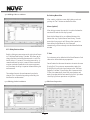
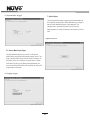
1.1 Open or Create Grand Concerto Configurator File
When you click on this button, the program goes to a Config.
File. There you can either open one of the existing
configurations or specify the name of a new file.
Configurations are saved with a .cfg extension.
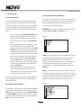
1.1 Retrieve Configuration from Grand Concerto
To retrieve a configuration from an existing Grand Concerto
installation, launch the Configurator software. Make sure
your computer is connected to the RS232 port on the back
panel of the Grand Concerto amplifier. The Startup screen
has two buttons. The first is used to open an existing
configuration or to create a new one. The second asks to
“Retrieve Existing Configuration From Grand Concerto.”
When you click on the “Retrieve” button, a progress window
will appear.
If you have this configuration already stored on your
computer's hard drive, you will see a dialog box asking if
you wish to overwrite the existing file. If this file is not
stored in your computer, this box will not appear.
1.1 Open or Create Grand Concerto Configurator
File
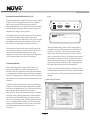
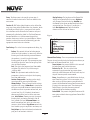
2.1 IR Libraries
The IR Library is a list of available components and their IR
function codes. The Configurator software stores captured IR
codes in a single directory. Once captured or downloaded,
the Configurator software will permanently store it as an .irc
file.
2.1 IR Libraries
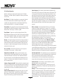
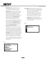
2.2 Adding a New Component to the IR Library
New component IR files are easily added by clicking on the
Add New button. This brings up a new window titled Add New
Component. In this window you must first enter the
manufacturer name and model. The Type drop-down menu
contains a large list of components. Each is a template of
common functions for that type of equipment. Clicking on
the type that matches the component will add the type name
in that field. If desired, you can add a type name that is not
in the drop-down menu.
Clicking on OK will automatically add the selected
component and associated functions to the IR Library.

13
Using the IR Learning Station Interface (fig. 9)
To record new IR codes, you will need the IR Learning Station
Interface. The IR Learning Station Interface is a powerful
tool for setting up new IR Libraries for use with the
Configurator Software, and is part of the IR Learning Station
Package. Capturing function codes and adding them to the
component IR Library is an easy process.
The Interface box is connected to your computer using one
of the RS232 connection cables provided with the IR
Learning Station package. Note that in many cases, personal
notebook computers do not have aDB9 serial cable. In this
case an RS232 to USB dongle cable will be necessary.
The back panel of the Interface box has two IR outputs for
testing purposes. You can use the included IR emitter and
attach it to the IR window on the face of the source
component, or to the built-in IR blaster, which, when aimed
at the source equipment, will fire the IR command.
Fig. 9
+
-
POWER
12VDC/0.4A
CONNECT TO
PC
CONNECT TO
CONCERTO D
IR
EMITTER
IR
BLASTER
Concerto Learning Station
Model NV-I8DLS
PASSTHRU
READY
IR SENSOR
TEST ACTIVE
POWER
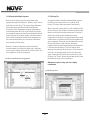
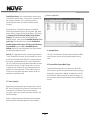
2.3 Recording IR codes
When a new component is added to the IR Library, it is
necessary to record the IR codes associated with each
function. To do this, connect the Learning Station Interface
as described above. Double-click on the desired component
from the IR Library page. This will open the IR Library Editor.
This window lists the complete set of functions for that type
of device.
To initiate the IR recording process, you can either double-
click on a function to be recorded or highlight the function
and click on the Record button. This will open the IR Library
Record window. The window will indicate that the
Configurator is “Waiting for IR Communications.” To record a
new code, simply point the component's remote control at
the IR receiver on the NuVo IR Learning Station Interface.
The first time you enter a code, the Configurator determines
if it is a “toggling function,” which means that the remote
actually sends two commands back-to-back. This requires
that the function button be pressed four times in
succession.
When the remote code is entered, the IR Library Record
window will go from yellow to green and indicate that the
capture was successful, and it will then return to yellow.
Repeat this procedure three more times until the desired
code is added to the IR Library Edit window. You will now see
the number of code repeats and the duration of the code. A
normal non-toggling remote will require two button pushes
to successfully record a command, while a toggling remote
will require four button pushes for each command.
If there is an error in recording the code, the display in the
Record window will indicate that there was a communication
error. If this occurs, click on the Record button and reenter
the code.
2.3 Recoding IR Codes

14
2.4 IR Library Default Key Assignment
Once the desired codes are added, assign them to the
appropriate key on the Display Pad. To do this, right-click on
each code and select “Keys.” This opens a drop-down menu
of the possible key selections for the Grand Concerto
Display Pad. Select the appropriate key for that command
and the Configurator will add it to the Default Key field for
that command. Keep in mind that the Grand Concerto Control
Pad has only five IR assignable buttons, so button control is
limited. More capability for control can be incorporated in
the macro tab covered later, and can then be added to the
menu capability of that source.
Once this sequence is completed, proceed to the next
function command, and repeat the above steps. When you
have assigned a default key for each IR, click on “Done” and
that component's IR Library is complete.
2.4 Library Default Key Assignment
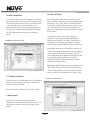
2.5 IR Library Test
An important feature of the Grand Concerto Configurator is
the ability to test each IR code as it is added to the IR
Library. This insures that every code will work reliably.
When a new code is added, while it is still highlighted, click
on the test button. This will open the IR Library Test window.
Make sure that the IR Learning Interface box's IR emitter is
either facing the IR receiver window of the source
equipment or an IR emitter is plugged into one of the two IR
emitter outputs and affixed to the IR receiver window of the
source equipment. Clicking on the test button will cause the
IR Learning interface to emit the code. The source
equipment should respond appropriately to the command if
it has been stored correctly. A test result box will open
where you can record yes or no to the test. Three successful
test results are required before the “Passed” count turns
green. Clicking the “OK” button will save the results in the
IR Library. The “Tested” column for that command will show
the number of successful tests performed.
Although not required, testing each code is highly
recommended.
2.5 IR Library Test

15
2.6 Adding a Function Code
If a required IR code is not in the list of codes, it is possible
to add a code to the list by clicking the “Create New” button.
The pull-down menu contains a list of all standard IR codes.
A name not found in the list can be typed in, but it is
recommended that you use the names provided in the list.
This conserves memory in the Grand Concerto. Clicking on
the “OK” button proceeds directly to the IR recording
process.
2.6 Adding a Function Code
2.7 Cleaning Up an IR Library
Unused IR codes can be deleted from the list by highlighting
the code and either clicking the ”Delete” button or right-
clicking and selecting “Delete.”
When you are finished editing the library, select “Done.”
3. Defining Sources
The “Sources” tab allows you to define the source
component attached to each of the six source inputs. All six
sources are not needed, but at least one source must be
defined.
3.1 Select or Edit Source
Double-clicking on a blank source will open the “Select
Source” window. This window assigns the appropriate source
number input. The “Display Name” is the text that will be
read on the Display Pad when that source is selected in any
zone. The display name can contain only capital letters,
numbers, and some punctuation. If an invalid key is typed, it
will be ignored.
The “Make” field defines the manufacturer of the
equipment. A drop-down menu allows you to choose a
source from the IR Library. The “Model” field provides a
drop-down menu that allows you to choose the specific
piece of source equipment from the selected manufacturer.
An important feature of the “Select Source” window is the
“Gain” level control. Different pieces of source equipment
tend to have different levels of audio output signal. This
slider control allows you to compensate for equipment that
has an inherently lower volume level. By using this
adjustment, when switching between sources, relative
volume levels remain constant.
When the appropriate information has been completed, click
“OK.” This will add the updated source information to the
“Source” window. When all the desired sources have been
defined, go to “Next” and proceed to the “Macros” setup.
3.1 Select or Edit Source

16
4. Macros
Each source defined in the “Source” step has a separate
Control Pad definition. The “Source to View” pull-down
menu provides the display name given to each source. Using
the “Next” and “Back” buttons will automatically cycle
through all defined sources.
An important feature of the NuVoNet Suite is the
communication with each Control Pad within the installation,
which eliminates the need for Macro Definitions. However, if
you do want to create specific strings of IR commands or use
the IR libraries of third-party source equipment to setup
functions within that source's Menu on the Control Pads, this
is the place to do that.
If the component had default keys defined in the IR Library,
single IR code macros will be automatically created for each
key. Hovering the mouse over each key in the Display Pad
picture on the left side of the screen will bring up a tool-tip
displaying the name of the macro assigned to that key.
Clicking on the key highlights the macro on the right side of
the screen.
Double-clicking on a key in either display will begin editing
the macro associated with that key.
4. Macros
4.1 Edit Macro Definition
The Macro Definition window has two separate points of
definition on the right side of the screen. The
top section allows a string of commands to be associate
with one of the five IR programmable buttons.
The bottom section automatically places the commands I
the menu selections at the Control Pads.
Examples of this use would be specific disc selection on a
multi-disc changer or specific station tuning
for satellite or cable receiver boxes.
The tree in the left-hand window displays all available IR
codes from the library. The tree is automatically expanded to
show the codes from the component associated with the
source.
Each macro has a “Display Name” that is used to describe
the macro. Before a macro can be saved, the name of the
macro must be established.
4.1 Edit Macro Definitions
4.1.1 Adding Codes to a Macro
A code is added to the macro by double-clicking on the
green IR code name in the library to the left. That code will
then be automatically added to the macro string to the right.
Up to 100 codes can be added to a single macro.

17
4.1.2 Editing Codes in a Macro
Double-clicking on a macro step on the right side will open
an “Edit Macro Code Settings” window. This allows you to
change the delay time before the command is issued. The
default delay is .25 seconds. This can be increased by .25-
second increments up to 30.5 seconds. Often a command
requires mechanical movement in the source equipment
and, therefore, the delay is important before initiating the
next command.
The number of repeats for each command can also be
changed. This is equivalent to pushing and holding the
button on the remote control.
4.1.1 Adding Codes to a Macro
4.1.2 Editing Codes in a Macro
Re-Ordering Macro Codes
After a code is added to a macro, highlighting a code and
pushing the Ý or ß button can reorder the codes.
Macros (updated)
After editing a macro, the macro list is updated to show the
number of IR codes and the display name.
Note that the Macro tab has an additional button at the
bottom that says “Update Macros From Library.” If codes
were edited in any way in an IR library after a source has
been defined in the Source tab, this button will
automatically pull those changes into the Macro Definition
window.
5. Zones
Up to 20 zones can be defined with the Grand Concerto. Each
zone can be defined with unique properties.
You will notice that the zone tab contains 20 entries for zone
Display Pads. The system can accommodate a total of 20
Display Pads by using the slave function in the “Edit Zone
Properties” window. A slave Display Pad is homerun to the
EZ Port, but automatically shares the same functions and
works in tandem with the main zone Display Pad. Up to three
slave Display Pads can operate on a single zone.
5.1 Edit Zone Properties

18
5.1 Edit Zone Properties
Double-clicking on a zone number opens the “Edit Zone
Properties” window. Specific properties defining that zone
are set here.
Max Volume: This allows the volume in a zone to be limited.
This can be done either to avoid damage to low-power
speakers or simply to prevent a certain room from being
turned up too high (e.g., a teenager's bedroom).
Party Volume: This controls the reset volume level for each
zone when the All On/Party Mode is initiated from any of the
Control Pads. The range is –78dB to –30dB.
Page Volume: If you are using the paging feature of the
Grand Concerto System, you can also set the specific volume
level of the page zone by zone, by using this volume control.
The range is –78dB to –30dB, with a default at –40dB.
Balance: The level of output to the left and right speakers is
adjusted here. The default is center, but depending on the
location of the speakers and the optimal listening area of
the room, it may be advantageous to adjust the balance to
either the left or the right.
Bass and Treble: Each of these EQ levels can be adjusted
individually. The range is -18dB to +18dB.
Volume Reset at Zone ON: A zone-specific feature is the
ability to have a zone automatically reset to a low volume
level when the zone is turned on. This check box initiates
that feature and is tied to the Zone Reset Volume level set
above it. If this box is not checked, the zone will turn on at
the last volume level.
Loudness Compensation ON: This box defaults to checked and
enables an automatic bass and treble boost when the zone is
at a low listening level. This EQ gradually flattens out as the
zone volume is increased. Unchecking the box turns this
function off.
Exclusive Source Control: Checking this box gives this zone
exclusive “do not disturb” control of any chosen source.
Other zones will have the ability to listen to that source, but
they will not have any specific function control.
Source Grouping: This allows for one zone to automatically
listen to the same source as all other zones in the group. This
is a very useful feature for a large open area where it is not
practical for more than one source to be playing at one time.
The advantage of the zone group is that each Display Pad
within the group has the ability to turn on or off, mute, and
control volume independently. This drop-down menu allows
any zone to be assigned to a group, or as an individual zone
with no group affiliation. Up to four distinct groups can be
created.
IR Pass-through: Each zone Control Pad has an IR receiver
for wireless remote control. By its nature, IR is susceptible
to external interference. To account for this, there is specific
IR pass-through settings for each Control Pad. IR Disabled
turns off the IR receiver completely and eliminates any
possibility of a competing light source. This is useful in an
environment in which the Control Pad receiver is competing
with overwhelming sunlight. This will prevent IR
communication throughout the system and therefore, it is
better to eliminate that light source. IR No Pass-through
prevents third-party remote control commands from being
accepted, but still allows the NuVo NV-I8GRC1 remote
control to operate the system. In some zones this is
necessary when a third-party remote is often used to control
a non–NuVo System source such as a TV. This would eliminate
that remote control's commands from being received by the
Control Pad and passed through to the source equipment.
Lock Zone By Default: This check box turns on a function that
automatically prevents any functionality from the zone until
the assigned security code is entered. Primarily, the
function prevents an outside zone from being turned on
except when the homeowner really wants to listen to it.
Do-Not-Disturb: This Section is used to lock out system-
wide commands from a specific zone.
No Master: Master and Party refer to the ability to turn all
zones on simultaneously. In some zones you may not want
this function.
No Page: The Grand Concerto System is capable of paging
through audio source input 6. This involves a phone system
that has a paging audio output and a means to provide a
voltage trigger. This is controlled using the Security tab to
set the voltage trigger and utilizing the Mute Input, see
Mute Input page, . This will be covered in the next tab.
La page est en cours de chargement...
La page est en cours de chargement...
La page est en cours de chargement...
La page est en cours de chargement...
La page est en cours de chargement...
La page est en cours de chargement...
La page est en cours de chargement...
La page est en cours de chargement...
La page est en cours de chargement...
La page est en cours de chargement...
La page est en cours de chargement...
La page est en cours de chargement...
La page est en cours de chargement...
La page est en cours de chargement...
La page est en cours de chargement...
La page est en cours de chargement...
-
 1
1
-
 2
2
-
 3
3
-
 4
4
-
 5
5
-
 6
6
-
 7
7
-
 8
8
-
 9
9
-
 10
10
-
 11
11
-
 12
12
-
 13
13
-
 14
14
-
 15
15
-
 16
16
-
 17
17
-
 18
18
-
 19
19
-
 20
20
-
 21
21
-
 22
22
-
 23
23
-
 24
24
-
 25
25
-
 26
26
-
 27
27
-
 28
28
-
 29
29
-
 30
30
-
 31
31
-
 32
32
-
 33
33
-
 34
34
-
 35
35
-
 36
36


Nuvo Cocerto NV-I8GXS Manuel utilisateur
- Catégorie
- Équipement musical supplémentaire
- Taper
- Manuel utilisateur
dans d''autres langues
- English: Nuvo Cocerto NV-I8GXS User manual
Documents connexes
-
Nuvo Concerto NV-I8DMS Manuel utilisateur
-
Nuvo Music port and music port elite Guide d'installation
-
-
-
-
-
-
-
-
Autres documents
-
Hama 00131799 Le manuel du propriétaire
-
AUSTRALIAN MONITOR ZMPS Manuel utilisateur
-
Williams Sound IR Plus Flex Manuel utilisateur
-
 DMP Electronics 1108 Guide d'installation
-
Bosch Appliances LTC 9418 Serie Manuel utilisateur
-
Allworx Tx 92/24 Guide d'installation
-
Hunter Douglas PowerView Manuel utilisateur
-
-
Elan EL-DB-BK Guide de démarrage rapide
-
Peavey PageMatrix Controller Manuel utilisateur
