Asco Series G2 Canopen Guide de démarrage rapide
- Taper
- Guide de démarrage rapide

G2-2 Series CANopen Quick Start Manual
Page 1
3835053 TDG22COQS1-1 5/07
Subject to change without notice
www.numatics.com/fieldbus
Getting Started
This is a brief document designed to quickly get you started setting up your valve manifold with an integrated
Numatics’ G2-2 CANopen communication node.
1) Initial Unpacking and Inspection
1) Examine exterior of package for signs of damage. Report any damage to shipping carrier.
2) Remove wrapped manifold assembly from box.
a) Remove manifold assembly from anti-static packaging
b) Retain documentation for installation and configuration
3) Examine manifold assembly for any shipping damage such as:
a) Bent pins or connectors
b) Report any damage to shipping carrier immediately
4) Examine manifold assembly for proper ordered configuration. (Valves, I/O, Protocol, etc.)
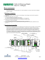
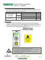
2) G2-2 Introduction
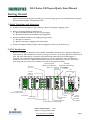
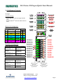
Below is an example of a 2012 series valve manifold. This fieldbus manifold series is capable of addressing a
total of 224 I/O. The manifold can be viewed as having two sections to it, the
Valve Side
and the
Discrete I/O
Side
. The
Valve Side
supports a maximum of 32 solenoid coils and the
Discrete I/O Side
supports a
maximum of 6 modules totaling 192 Outputs, 96 Inputs, or various combinations. The communication
module has two connectors: a 5-pin communication connector and a 4-pin power connector. Pin-outs for
these, along with I/O connectors, are labeled on the side of the respective modules.
Valve
I/O Point
LED Status
Indicator(s)
Discrete I/O
Connectors
Discrete I/O Side
(Maximum of 6 Modules)
Valve Side
(Maximum of 32 Solenoids)
Module/
Network
Status LED's
Chassis Ground
Connection
Valve
End Plates
Manual
Override
Solenoid LED
Status Indicator
Valve Side
Sub-D Output
Module
Communications
Module
Manual Configuration
Module (MCM)
Terminal Strip Module
8 Connector I/O Module
19 Pin Round
Connector Module
Analog Module
Dual 25 Pin Sub-D
w/Aux Power Output Module
+24V NODE/IN
ERROR
RUN
+24V VLV/OUT
FUSE 1
FUSE 2
CANopen

G2-2 Series CANopen Quick Start Manual
Page 2
3835053 TDG22COQS1-1 5/07
Subject to change without notice
www.numatics.com/fieldbus
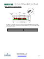
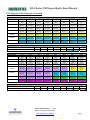
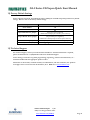
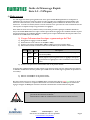
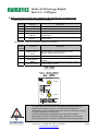
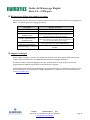
3) MCM - Manual Configuration Module
The MCM is the module that allows the user to manually set baud rate, MAC ID and other user definable
options. The MCM consists of two DIP switch sets (SW1 and SW2) and two rotary switches (SW3 and SW4).
MCM Module Part Numbers
Description Part Number
Complete Module 239-1384
Replacement Board 256-684
(SW2)
(SW3)
DIP Switch
(SW1)
DIP Switch
(SW4)
All DIP switches shown in the "OFF" position
Rotary Switch
Rotary Switch
1
4
3
2
5
6
7
8
ON
1
4
3
2
5
6
7
8
ON

G2-2 Series CANopen Quick Start Manual
Page 3
3835053 TDG22COQS1-1 5/07
Subject to change without notice
www.numatics.com/fieldbus
MCM Settings
DIP Switch Settings (SW1)
Baud Rate:
SW1-1 SW1-2 Kbaud
Off* Off* 125*
Off On 250
On Off 500
On On 1000
Manual or Software Configuration:
Switch Setting Description
SW1-5 Off
MCM Disabled - Ignore MCM Settings
SW1-5 On*
MCM Enabled - Use MCM Settings
DIP Switch Settings (SW2)
Hundreds Digit:
Switch Setting Description
SW2-1 Off* Hundreds digit off
SW2-1 On Hundreds digit on (add 100 to rotary switch setting)
Output Status:
Switch Setting Description
SW2-7 Off* Enable the Output Status bits for the CANopen Module
SW2-7 On Disable the Output Status bits for the CANopen Module
Set Defaults:
Switch Setting Description
SW2-8 Off* Maintains all current PDO settings
SW2-8 On
Set all PDOs to the defaults as defined in the CANopen Specification,
CiA DS 401 V 2.1
Rotary Switch Settings (SW3 and SW4)
MAC ID (Network Address):
Switch Description
SW3 Sets the Ones Digits
SW4 Sets the Tens Digits
*Factory Default Settings
SW1-5 MUST be on for the CANopen module to be functional.
DIP and rotary switch settings do not take effect until power is cycled
(turned OFF and ON).

G2-2 Series CANopen Quick Start Manual
Page 4
3835053 TDG22COQS1-1 5/07
Subject to change without notice
www.numatics.com/fieldbus
4) Self-Test Mode
An internal diagnostic tool can also be enabled using the optional MCM module. This tool allows the user to
confirm that all of the Inputs and Outputs on the manifold are fully functional without needing a network
connection or controller. There are two test modes that the user can choose using SW2-8. The “Output” test
mode tests all the outputs by sequentially turning them ON one at a time. The “Input/Output” test mode
tests the inputs by causing all of the outputs to toggle between even and odd values when any input is made.
To use the Self-Test Mode, the user must first set some initial conditions using the MCM module. Follow
these steps to obtain the needed initial condition settings. Remember to remove power from the manifold
before making changes to the MCM when setting these initial conditions.
1) Disconnect power and air from the manifold!
2) Record current MCM settings.
3) Set the rotary switches to 99 (SW3 and SW4).
4) Make sure that SW1-5, SW2-1, and SW2-7 are in the “ON” position.
5) Select the desired test mode with SW2-8 (see table below)
Switch
T
esting
Mode
Setting Description
Output Off Sequentially turns all the outputs ON and OFF.
SW2-8
Input/
Output
On
Causes all of the odd outputs to come on and stay on until an
input is made. When an input is made, the outputs will toggle to
the even outputs.
6) Make sure that all of the other switches are in the “OFF” position.
The initial conditions are now set. To enable the Self-Test Mode, apply power to the manifold and make the
following changes while the module status LED is blinking (within 2 to 5 seconds of power up):
1) Set SW2-6 to the “ON” position.
2) Set SW2-7 to the “OFF” position.
Once Self-Test Mode is enabled, the module status LED will flash red/green until Self-Test Mode is
terminated by removing power to the unit. Remember to return the MCM settings to their original settings to
return the communication node to normal operation.
!
Air should be disconnected to the manifold when attempting to run the
Self-Test Mode to prevent unwanted motion.
Communication lines should be disconnected before attempting to run the
Self-Test Mode.

G2-2 Series CANopen Quick Start Manual
Page 5
3835053 TDG22COQS1-1 5/07
Subject to change without notice
www.numatics.com/fieldbus
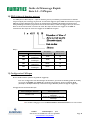
5) I/O Mapping Example
Discrete I/O Configuration
Objects Pos
No.
Module Type Part No.
I O
1 MCM 239-1384 -- --
2
8O Sourcing
(PNP)
239-1315 1 1
3
16O Sourcing
(PNP)
239-1319 1 2
4
4I Sinking
(NPN)
239-1304 1 0
5
8I Sinking
(NPN)
239-1308 1 0
Manifold I/O Configuration
Output Sub-indexes and Mapping Locations
-Valve Output
Sub-indexes = 2
0x6200 01 08
0x6200 02 08
-Allocated Valve
Output
Sub-indexes = 2
0x6200 03 08
0x6200 04 08
-Discrete Output
Sub-indexes = 3
0x6200 05 08-
0x6200 07 08
Total Output Sub-indexes = 7
Input Sub-indexes and Mapping Locations
-Valve Status Input
Sub-indexes = 4
0x6000 01 08-
0x6000 04 08
-Discrete Output
Status
Sub-indexes = 2
0x6000 05 08
0x6000 06 08
-Discrete Input
Sub-indexes = 2
0x6000 07 08
0x6000 08 08
Total Input Sub-indexes = 8
Example:
Assumed Settings
- Single Z-Boards
TM
used with single solenoid
valves
- Double Z-Boards
TM
used with double solenoid
valves
When the 14 End
Solenoid is
energized, the 4 port
is pressurized.
When the 12 End
Solenoid is
energized, the 2 port
is pressurized.

G2-2 Series CANopen Quick Start Manual
Page 6
3835053 TDG22COQS1-1 5/07
Subject to change without notice
www.numatics.com/fieldbus
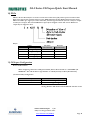
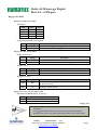
I/O Mapping Table Example Continued
Output Table
SUB-INDEX Bit 7 Bit 6 Bit 5 Bit 4 Bit 3 Bit 2 Bit 1 Bit 0
6200 01 08
Valve Coil
No. 8
Valve Coil
No. 7
Valve Coil
No. 6
Valve Coil
No. 5
Valve Coil
No. 4
Valve Coil
No. 3
Valve Coil
No. 2
Valve Coil
No. 1
6200 02 08
Allocated &
Reserved
Allocated &
Reserved
Allocated &
Reserved
Allocated &
Reserved
Valve Coil
No. 12
Valve Coil
No. 11
Valve Coil
No. 10
Valve Coil
No. 9
6200 03 08
Allocated &
Reserved
Allocated &
Reserved
Allocated &
Reserved
Allocated &
Reserved
Allocated &
Reserved
Allocated &
Reserved
Allocated &
Reserved
Allocated &
Reserved
6200 04 08
Allocated &
Reserved
Allocated &
Reserved
Allocated &
Reserved
Allocated &
Reserved
Allocated &
Reserved
Allocated &
Reserved
Allocated &
Reserved
Allocated &
Reserved
6200 05 08
Discrete
Output No. 7
Discrete
Output No. 6
Discrete
Output No. 5
Discrete
Output No. 4
Discrete
Output No. 3
Discrete
Output No. 2
Discrete
Output No. 1
Discrete
Output No. 0
6200 06 08
Discrete
Output No. 7
Discrete
Output No. 6
Discrete
Output No. 5
Discrete
Output No. 4
Discrete
Output No. 3
Discrete
Output No. 2
Discrete
Output No. 1
Discrete
Output No. 0
6200 07 08
Discrete
Output No. 15
Discrete
Output No. 14
Discrete
Output No. 13
Discrete
Output No. 12
Discrete
Output No. 11
Discrete
Output No. 10
Discrete
Output No. 9
Discrete
Output No. 8
Output Table
OBJECT Byte 0 Byte 1 Byte 2 Byte 3 Byte 4 Byte 5 Byte 6 Byte 7
1
st
Received PDO Object 1600 62000108 62000208 62000308 62000408 62000508 62000608 62000708
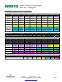
Input Table
SUB-INDEX Bit 7 Bit 6 Bit 5 Bit 4 Bit 3 Bit 2 Bit 1 Bit 0
6000 01 08
Coil No. 8
Status
Coil No. 7
Status
Coil No. 6
Status
Coil No. 5
Status
Coil No. 4
Status
Coil No. 3
Status
Coil No. 2
Status
Coil No. 1
Status
6000 02 08
Coil No. 16
Status
Coil No. 15
Status
Coil No. 14
Status
Coil No. 13
Status
Coil No. 12
Status
Coil No. 11
Status
Coil No. 10
Status
Coil No. 9
Status
6000 03 08
Coil No. 24
Status
Coil No. 23
Status
Coil No. 22
Status
Coil No. 21
Status
Coil No. 20
Status
Coil No. 19
Status
Coil No. 18
Status
Coil No. 17
Status
6000 04 08
Coil No. 32
Status
Coil No. 31
Status
Coil No. 30
Status
Coil No. 29
Status
Coil No. 28
Status
Coil No. 27
Status
Coil No. 26
Status
Coil No. 25
Status
6000 05 08
Allocated &
Reserved
Allocated &
Reserved
Allocated &
Reserved
Allocated &
Reserved
Allocated &
Reserved
Allocated &
Reserved
Status for
Discrete
Outputs
No. 4-7
Status for
Discrete
Outputs
No. 0-3
6000 06 08
Allocated &
Reserved
Allocated &
Reserved
Allocated &
Reserved
Allocated &
Reserved
Status for
Discrete
Outputs
No. 12-15
Status for
Discrete
Outputs
No. 8-11
Status for
Discrete
Outputs
No. 4-7
Status for
Discrete
Outputs
No. 0-3
6000 07 08
Allocated &
Reserved
Allocated &
Reserved
Allocated &
Reserved
Allocated &
Reserved
Discrete
Input No. 3
Discrete
Input No. 2
Discrete
Input No. 1
Discrete
Input No. 0
6000 08 08
Discrete
Input No. 7
Discrete
Input No. 6
Discrete
Input No. 5
Discrete
Input No. 4
Discrete
Input No. 3
Discrete
Input No. 2
Discrete
Input No. 1
Discrete
Input No. 0
Input Table
OBJECT Byte 0 Byte 1 Byte 2 Byte 3 Byte 4 Byte 5 Byte 6 Byte 7
1
st
Transmitted PDO Object 1A00 60000108 60000208 60000308 60000408 60000508 60000608 60000708 60000808

G2-2 Series CANopen Quick Start Manual
Page 7
3835053 TDG22COQS1-1 5/07
Subject to change without notice
www.numatics.com/fieldbus
6) Output Short Circuit Protection (Status Input Bits)
Status Input Bits report the integrity of the load being driven by the output driver. They must be mapped to
the scanner as part of the Input Size Value. Please refer to the table below for Status Input Bit action during
fault condition:
Output Type Output State Fault Condition Status Bit
No Fault
0
ON
Fault -
Short Circuit, Over Temp/Over Current 1
No Fault
0
Valve Solenoid Coil Driver or
Sinking (NPN)
Discrete Outputs
OFF
Fault -
Open Load 1
No Fault 0 Sourcing (PNP)
Discrete Outputs
ON
Fault -
Short Circuit, Over Temp/Over Current 1
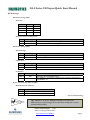
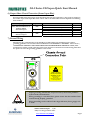
7) Ground Wiring
All Numatics Inc. communication nodes should be grounded during the installation process. These
grounding guidelines can be found in National Electrical code IEC 60204-1 or EN 60204-1. There also is a,
“ATTENTION: CONNECT TO EARTH GROUND FOR PROPER GROUNDING OF UNIT”, label
attached to the chassis ground connection point on the G2-2 series communication node housing. This label
also points out where the grounding guidelines can be found.
Proper grounding will alleviate and prevent many intermittent problems
with network communication.
When grounding to a machine frame, please ensure that the machine frame
itself is already properly grounded.
Better grounding can be achieved when larger diameter (lower gauge) wire
is used.
!
ATTENTION:
CONNECT TO EARTH
GROUND FOR PROPER
GROUNDING OF UNIT
Reference National
Electrical code
IEC 60204-1 or EN 60204-1
for grounding guidelines
+24V NODE/IN
ERROR
RUN
+24V VLV/OUT
FUSE 1
FUSE 2
CANopen

G2-2 Series CANopen Quick Start Manual
Page 8
3835053 TDG22COQS1-1 5/07
Subject to change without notice
www.numatics.com/fieldbus
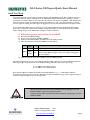
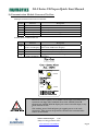
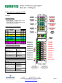
8) Communication Module Connector Pin-Outs
CANopen Communication Connector Pin-Out
Pin No. Function Description
1 Shield Cable shield
2 V+ Bus Power, 11-25VDC
3 V- Bus Power, Common
4 CAN_H Controller Area Network High, Communication Line
5 CAN_L Controller Area Network Low, Communication Line
Auxiliary Power Connector Pin-out
Standard
Pin No.
Function Description
1
+24VDC
(Valves and Outputs)
Voltage Used to Power Outputs
(Valve Coils and Discrete Outputs)
2 Earth Ground Protective Earth (Case Ground)
3 0VDC Common 0VDC Common, for Valves, I/O, and Node Power
4
+24VDC
(Node and Inputs)
Voltage Used to Power Discrete Inputs and Node
Electronics
Maximum current capacity on the 0VDC common pin of auxiliary power
connector is 8 Amps. The combined draw of the +24VDC Valves &
Outputs and +24VDC Node & Inputs pins cannot exceed 8 Amps, at any
given moment in time.
The auxiliary power Node & Inputs pin supplies power to the node
electronics. This pin must be powered at all times for communication
node to be functional.
!
2
1
AUX
1
4
3
MALE
2
COM
4
MALE
5
3
CANopen
TM

G2-2 Series CANopen Quick Start Manual
Page 9
3835053 TDG22COQS1-1 5/07
Subject to change without notice
www.numatics.com/fieldbus
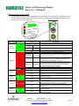
9) LED Functions
Upon power up, the LEDs indicate the status of the unit. There are six LEDs on the G2-2 CANopen node;
one for Run, one for Error, two for internal fuse integrity and two for Aux. Power status.
LED
Name
Color Status Description
OFF Device is not currently powered.
SINGLE
FLASH
Stopped – The device is in a STOPPED state
BLINKING
Pre-Operational – The device is in a Pre-Operational state
RUN Green
ON Operational – The device is in the operational state
OFF No Error - The device is in working condition
SINGLE
FLASH
Warning Limit Reached – At least one of the error counters of
the CAN controllers has reached or exceeded the warning level
(too many error frames)
DOUBLE
FLASH
Error Control Event – A guard event (NMT- Slave or NMT-
master) or a heartbeat event (Heartbeat consumer) has
occurred
TRIPLE
FLASH
Sync Error – The sync message has not been received within
the configured communication cycle period time out
(see Object Dictionary Entry 0x1006)
Red
ON Bus off – The CAN controller is bus off
ERROR
Green Red FLASHING Module is in self-test mode.
OFF
Internal fuse
F1
is OK (valid only when power is applied to
+24V
VLV / OUT
pin on Aux. Power connector).
FUSE 1 Red
ON
Internal fuse
F1
is open; No power is internally provided to
valves or outputs. Communication NOT affected.
OFF
No DC Power present at
+24V
VLV / OUT
pin on Aux. Power
connector.
+24V
VLV/OUT
Green
ON
DC Power applied to
+24V
VLV / OUT
pin on Aux. Power
Connector.
OFF
Internal fuse
F2
is OK (valid only when power is applied to
+24V
NODE / IN
pin on Aux. Power connector.
FUSE 2 Red
ON
Internal fuse
F2
is open; No power is internally provided to
node electronics or inputs. Communication Node will not
function.
OFF
No DC Power present at
+24V
NODE / IN
pin on Aux. Power
connector. +24V
NODE/IN
Green
ON
DC Power applied to
+24V
NODE / IN
pin on Aux. Power
connector.
FUSE 1
+24V VLV/OUT
+24V NODE/IN
FUSE 2
CANopen
RUN
ERROR
+24V NODE/IN
ERROR
RUN
+24V VLV/OUT
FUSE 1
FUSE 2
CANopen

G2-2 Series CANopen Quick Start Manual
Page 10
3835053 TDG22COQS1-1 5/07
Subject to change without notice
www.numatics.com/fieldbus
10) PDOs
PDOs or Process Data Objects are used to transfer the real time data (I/O) with no protocol overhead. The
G2-2 series supports four transmit and four receive PDOs defined in the Pre-Defined Connection Set. Each
PDO can transfer up to eight bytes of data. Therefore, the G2-2 logical maximum I/O size is 32 bytes of input
and 32 bytes of output. The transmit PDOs have input objects mapped to them. The receive PDOs have
output objects mapped to them.
Object:
Object
Value Description
Sub-index
(Hexadecimal)
Bit Value
(Hexadecimal)
6000 Digital Inputs 01-20 08
6200 Digital Outputs 01-20 08
6400 Analog Inputs 01-0C 10
6401 Analog Outputs 01-0C 10
11) CANopen Configuration
Device Profile Number
When configuring a Numatics CANopen manifold, add the Device Profile as a “GENERIC I/O
MODULE”. Also add the Device Type Number as a 401 D (decimal) or 191 H (Hexadecimal).
I/O Functionality Configuration
Numatics CANopen Version I/O Functionality
Version ≤ 1.5 Add ONLY Digital I/O*
Version >1.5 Add both Analog and Digital I/O
*Analog Modules ARE FULLY FUNCTIONAL with this version

G2-2 Series CANopen Quick Start Manual
Page 11
3835053 TDG22COQS1-1 5/07
Subject to change without notice
www.numatics.com/fieldbus
12) Factory Default Settings
Unless otherwise requested, all standard G2-2 Series CANopen manifolds ship with specific factory default
settings. Below is a list of the factory default settings:
13) Technical Support
For technical support, contact your local Numatics distributor. If further information is required,
please call Numatics Inc. at (248) 887-4111 and ask for Technical Support.
Issues relating to network set-up, PLC programming, sequencing, software related functions, etc…
should be handled with the appropriate product vendor.
Information on device files, technical manuals, local distributors, and other Numatics, Inc. products
and support issues can be found on the Numatics, Inc’s. WEB site at www.numatics.com
Description Default Settings
Node Address 00
Baud Rate 125 KB
Input Module Power Jumper
PU
(Input sensor power supplied by
+24VDC Node and Inputs pin on the Aux. power connector)
Output Module Power Jumper
SP
(Output module power supplied by
+24VDC Valves and Outputs pin on the Aux. power connector)
Valve Side Output Bytes 4 Bytes (32 Allocated Valve Coil Outputs)
Discrete I/O Side - I/O Bytes Self-Configuring based on the I/O modules installed.

Guide de Démarrage Rapide
Série 2-2 - CANopen
Page 1
8385053 TDG22COQS1-1 5/07
Sous réserve de modification sans avis préalable
www.numatics.com/fieldbus
Pour commencer
Ce document décrit le démarrage rapide de votre îlot de distribution à nœud de communication CANopen
série G2-2 intégré.
1) Déballage et inspection
1) Inspectez l'emballage extérieur pour détecter tout dommage. Tout dommage constaté doit être signalé au
transporteur.
2) Retirez l'ensemble de l'îlot de son carton.
a) Sortez l'ensemble de son emballage anti-statique.
b) Conservez la documentation portant sur l'installation et la configuration.
3) Inspectez l'ensemble de l'îlot pour détecter tout dommage de transport tel que:
a) Broches ou connecteurs déformés
b) Tout dommage constaté doit être immédiatement signalé au transporteur.
4) Vérifiez que la configuration de l'ensemble de l'îlot livré correspond à votre commande. (distributeurs, E/S,
protocole, …).
2) Introduction à la série G2-2
Ci-dessous un exemple représentant l'ensemble d'un îlot de distributeurs de la série 2012. Cette série d'îlots à
bus de terrain est capable d'adresser un total de 224 E/S. L'îlot peut être considéré comme ayant deux
parties: la partie
Composants pneumatiques
et la partie
Composants électroniques
. La partie Composants
pneumatiques supporte un maximum de 32 bobines et la partie Composants électroniques supporte un
maximum de 6 modules, donc un total de 192 sorties, 96 entrées ou de différentes combinaisons de celles-ci.
Le module de communication est équipé de deux connecteurs : un connecteur de communication à 5 broches
et un connecteur d'alimentation à 4 broches. L'affectation des broches ainsi que les connecteurs E/S sont
repérés sur la face latérale de chaque module.
Valve
I/O Point
LED Status
Indicator(s)
Discrete I/O
Connectors
Discrete I/O Side
(Maximum of 6 Modules)
Valve Side
(Maximum of 32 Solenoids)
Module/
Network
Status LED's
Chassis Ground
Connection
Valve
End Plates
Manual
Override
Solenoid LED
Status Indicator
Valve Side
Sub-D Output
Module
Communications
Module
Manual Configuration
Module (MCM)
Terminal Strip Module
8 Connector I/O Module
19 Pin Round
Connector Module
Analog Module
Dual 25 Pin Sub-D
w/Aux Power Output Module
+24V NODE/IN
ERROR
RUN
+24V VLV/OUT
FUSE 1
FUSE 2
CANopen

Guide de Démarrage Rapide
Série 2-2 - CANopen
Page 2
8385053 TDG22COQS1-1 5/07
Sous réserve de modification sans avis préalable
www.numatics.com/fieldbus
3) MCM – Module de configuration manuelle (option)
Le MCM (module de configuration manuelle) permet à l'utilisateur de configurer manuellement le taux baud,
l'identificateur MAC ID et les autres options définissables par l'utilisateur. Le MCM est équipé de deux
ensembles de DIP switchs (SW1 et SW2) et de deux roues codeuses (SW3 et SW4).
Codes des composants du module MCM
Description Code
Module complet 239-1384
Carte de rechange 256-684
(SW2)
(SW3)
DIP Switch
(SW1)
DIP Switch
(SW4)
All DIP switches shown in the "OFF" position
Rotary Switch
Rotary Switch
1
4
3
2
5
6
7
8
ON
1
4
3
2
5
6
7
8
ON

Guide de Démarrage Rapide
Série 2-2 - CANopen
Page 3
8385053 TDG22COQS1-1 5/07
Sous réserve de modification sans avis préalable
www.numatics.com/fieldbus
Réglages du MCM
Réglages des DIP switchs (SW1)
Taux Baud :
SW1-1 SW1-2 Kbaud
Off* Off* 125*
Off On 250
On Off 500
On On 1000
Configuration manuelle ou par logiciel :
Switch Réglage Description
SW1-5 Off
MCM désactivé – Ignorer les réglages MCM
SW1-5 On*
MCM activé – Utiliser les réglages MCM
Réglages des DIP switchs (SW2)
Chiffre des centaines :
Switch Réglage Description
SW2-1 Off* Chiffre des centaines désactivé
SW2-1 On Chiffre des centaines activé (ajouter 100 au réglage de la roue codeuse)
Etat des sorties :
Switch Réglage Description
SW2-7 Off* Activer les bits d'état de sortie pour le module CANopen
SW2-7 On Désactiver les bits d'état de sortie pour le module CANopen
Réglages par défaut :
Switch Réglage Description
SW2-8 Off*
Maintien de tous les réglages PDO actuels (Process Data Objects =
objet
s
de données process
)
SW2-8 On
Remise au défaut de tous les réglages PDO définis dans la spécification
CANopen CiA DS 401 V2.1
Réglages des roues codeuses (SW3 et SW4)
Identificateur MAC ID (adresse du réseau) :
Switch Description
SW3 Mise au point des chiffres des unités
SW4 Mise au point des chiffres des dizaines
*Réglage usine
SW1-5 doit impérativement être activé pour que le module CANopen puisse
fonctionner.
Les réglages des DIP switchs et roues codeuses ne prennent effet qu'au
prochain cycle de mise sous tension (mise hors tension et mise sous tension).

Guide de Démarrage Rapide
Série 2-2 - CANopen
Page 4
8385053 TDG22COQS1-1 5/07
Sous réserve de modification sans avis préalable
www.numatics.com/fieldbus
4) Mode auto-test
Un outil diagnostic interne peut également être activé par le module MCM optionnel. Cet outil permet à
l'utilisateur de s'assurer que toutes les entrées et sorties sur l'îlot sont complètement opérationnelles, sans
besoin de connexion réseau, ni de contrôleur. Le switch SW2-8 permet à l'utilisateur de choisir entre deux
modes test. Le mode test “Entrée/Sortie” teste les entrées de sorte que toutes les sorties commutent entre les
valeurs paires et impaires lorsqu'un signal d'entrée est appliqué.
Pour utiliser le mode auto-test, l'utilisateur doit, tout d'abord, paramétrer quelques conditions initiales au
moyen du module MCM. Suivre les étapes suivantes pour obtenir les réglages des conditions initiales requises.
Lors du paramétrage des conditions initiales, n'oubliez pas de couper l'alimentation électrique de l'îlot avant
d'effectuer les modifications sur le MCM.
1) Couper l'alimentation électrique et pneumatique de l'îlot!
2) Enregistrez les réglages actuels du MCM.
3) Positionnez les roues codeuses sur 99 (SW3 et SW4).
4) Assurez-vous que les switchs SW1-5, SW2-1 et SW2-7 sont sur la position “ON”.
5) Sélectionnez le mode test désiré à l'aide du switch SW2-8 (voir le tableau ci-dessous).
Switch
Mode
test
Réglage Description
Sortie Off
Les sorties sont successivement mises sous tension (ON), puis
hors tension (OFF).
SW2-8
Entrée/
Sortie
On
Les sorties impaires sont mises sous tension et restent sous
tension jusqu'à ce qu'un signal d'entrée est appliqué. Lorsqu'un
signal d'entrée est appliqué, les sorties commutent sur les sorties
paires.
6) Assurez-vous que tous les autres switchs sont sur la position “OFF”.
Le réglage des condition initiales est alors terminé. Pour activer le mode auto-test, mettez l'îlot sous tension
et faites les modifications suivantes pendant que la LED d'état du module clignote (pendant les premières 2 à
5 secondes) :
1) Placez le switch SW2-6 sur la position “ON”.
2) Placez le switch SW2-7 sur la position “OFF”.
Dès que le mode auto-test est activé, la LED Bus Error (erreur de bus) clignote rouge/vert jusqu'à ce que le
mode auto-test est terminé en coupant l'alimentation en tension du module. N'oubliez pas de remettre les
réglages d'origine du MCM pour remettre le nœud de communication en fonctionnement régulier.
!
Avant de lancer le mode auto-test, coupez l'alimentation en air de l'îlot pour
prévenir les mouvements accidentels.
Débranchez les câbles de communication avant de lancer le mode auto-test.

Guide de Démarrage Rapide
Série 2-2 - CANopen
Page 5
8385053 TDG22COQS1-1 5/07
Sous réserve de modification sans avis préalable
www.numatics.com/fieldbus
5) Exemple de mapping des E/S
Configuration des E/S discrètes
Objets No.
de
pos
Type de
module
Code
I O
1 MCM 239-1384 -- --
2
8O Sourcing
(PNP)
239-1315 1 1
3
16O Sourcing
(PNP)
239-1319 1 2
4
4I Sinking
(NPN)
239-1304 1 0
5
8I Sinking
(NPN)
239-1308 1 0
Configuration des E/S de l'îlot
Allocation sub-indices des sorties et mapping
Sub-indices des sorties
distr. = 2
0x6200 01 08
0x6200 02 08
Sub-indices des
sorties distr. alloués
= 2
0x6200 03 08
0x6200 04 08
Sub-indices des
sorties discrètes = 3
0x6200 05 08-
0x6200 07 08
Nb. total de sub-indices de sorties distr. = 7
Allocation sub-indices des entrées et
mapping
Sub-indices de l'état
des entrées distr. = 4
0x6000 01 08-
0x6000 04 08
Sub-indices de l'état
des sorties discrètes
= 2
0x6000 05 08
0x6000 06 08
-Sub-indices des
entrèes discrètes = 2
0x6000 07 08
0x6000 08 08
Nb. total de sub-indices des entrées = 8
Exemple:
Réglages présumés
- Cartes Z-Boards
TM
simples utilisés avec les
électrodistributeurs simples.
- Cartes Z-Boards
TM
doubles utilisés avec les
électrodistributeurs doubles.
When the 14 End
Solenoid is
energized, the 4 port
is pressurized.
When the 12 End
Solenoid is
energized, the 2 port
is pressurized.

Guide de Démarrage Rapide
Série 2-2 - CANopen
Page 6
8385053 TDG22COQS1-1 5/07
Sous réserve de modification sans avis préalable
www.numatics.com/fieldbus
Exemple de mapping des E/S - continuation
Tableau des sorties
SUB-INDICE Bit 7 Bit 6 Bit 5 Bit 4 Bit 3 Bit 2 Bit 1 Bit 0
6200 01 08
Bobine no. 8 Bobine no. 7 Bobine no. 6 Bobine no. 5 Bobine no. 4 Bobine no. 3 Bobine no. 2 Bobine no. 1
6200 02 08
Alloué et
réservé
Alloué et
réservé
Alloué et
réservé
Alloué et
réservé
Bobine no. 12 Bobine no. 11 Bobine no. 10 Bobine no. 9
6200 03 08
Alloué et
réservé
Alloué et
réservé
Alloué et
réservé
Alloué et
réservé
Alloué et
réservé
Alloué et
réservé
Alloué et
réservé
Alloué et réservé
6200 04 08
Alloué et
réservé
Alloué et
réservé
Alloué et
réservé
Alloué et
réservé
Alloué et
réservé
Alloué et
réservé
Alloué et
réservé
Alloué et réservé
6200 05 08
Sortie discrète
7
Sortie discrète
6
Sortie discrète
5
Sortie discrète
4
Sortie discrète
3
Sortie discrète
2
Sortie discrète 1 Sortie discrète 0
6200 06 08
Sortie discrète
7
Sortie discrète
6
Sortie discrète
5
Sortie discrète
4
Sortie discrète
3
Sortie discrète
2
Sortie discrète 1 Sortie discrète 0
6200 07 08
Sortie discrète
15
Sortie discrète
14
Sortie discrète
13
Sortie discrète
12
Sortie discrète
11
Sortie discrète
10
Sortie discrète
9
Sortie discrète 8
Tableau des sorties
OBJET Octet 0 Octet 1 Octet 2 Octet 3 Octet 4 Octet 5 Octet 6 Octet 7
1
er
PDO Object 1600 reçu 62000108 62000208 62000308 62000408 62000508 62000608 62000708
Tableau des entrées
SUB-INDICE Bit 7 Bit 6 Bit 5 Bit 4 Bit 3 Bit 2 Bit 1 Bit 0
6000 01 08
Etat bobine 8 Etat bobine 7 Etat bobine 6 Etat bobine 5 Etat bobine 4 Etat bobine 3 Etat bobine 2 Etat bobine 1
6000 02 08
Etat bobine 16 Etat bobine 15 Etat bobine 14 Etat bobine 13 Etat bobine 12 Etat bobine 11 Etat bobine 10 Etat bobine 9
6000 03 08
Etat bobine 24 Etat bobine 23 Etat bobine 22 Etat bobine 21 Etat bobine 20 Etat bobine 19 Etat bobine 18 Etat bobine 17
6000 04 08
Etat bobine 32 Etat bobine 31 Etat bobine 30 Etat bobine 29 Etat bobine 28 Etat bobine 27 Etat bobine 26 Etat bobine 25
6000 05 08
Alloué et
réservé
Alloué et
réservé
Alloué et
réservé
Alloué et
réservé
Alloué et
réservé
Alloué et
réservé
Etat des sorties
discrètes 4-7
Status for
Discrete
Outputs
No. 0-3
6000 06 08
Alloué et
réservé
Alloué et
réservé
Alloué et
réservé
Alloué et
réservé
Etat des sorties
discrètes 12-15
Etat des sorties
discrètes 8-11
Etat des sorties
discrètes 4-7
Etat des sorties
discrètes 0-3
6000 07 08
Alloué et
réservé
Alloué et
réservé
Alloué et
réservé
Alloué et
réservé
Entrée discrète
3
Entrée discrète
2
Entrée discrète
1
Entrée discrète 0
6000 08 08
Entrée discrète
7
Entrée discrète
6
Entrée discrète
5
Entrée discrète
4
Entrée discrète
3
Entrée discrète
2
Entrée discrète
1
Entrée discrète 0
Tableau des entrées
OBJET Octet 0 Octet 1 Octet 2 Octet 3 Octet 4 Octet 5 Octet 6 Octet 7
1
er
PDO Object 1A00 transmis 60000108 60000208 60000308 60000408 60000508 60000608 60000708 60000808

Guide de Démarrage Rapide
Série 2-2 - CANopen
Page 7
8385053 TDG22COQS1-1 5/07
Sous réserve de modification sans avis préalable
www.numatics.com/fieldbus
6) Protection des sorties contre les courts-circuits (bits d'entrée d'état)
Les bits d'entrée d'état signalent l'intégrité de la charge pilotée par le pilote de sortie. Ils doivent être mappés
sur le scanner comme partie de la valeur de la taille de l'entrée. Voir le tableau ci-dessous pour l'action du bit
d'entrée d'état lors de l'occurrence d'une condition de défaut:
Type de sortie Etat de sortie Condition de défaut Bit d'état
Sans défaut
0
ON
Défaut –
court-circuit, surchauffe/surintensité de
courant
1
Sans défaut
0
Pilote de la bobine
d'électrodistributeur ou
Sinking (NPN)
Sorties discrètes
OFF
Défaut –
charge ouverte 1
Sans défaut 0 Sourcing (PNP)
Sorties discrètes
ON
Défaut –
court-circuit, surchauffe/surintensité de
courant
1
7) Mise à la terre
Tous les nœuds de communication de Numatics Inc. doivent être mis à la terre pendant la procédure
d'installation. Les exigences relatives à la mise à la terre sont fournies dans les normes CEI 60204-1 ou
EN 60204-1. Une étiquette d'avertissement “ATTENTION: RELIER L'EQUIPEMENT A UNE PRISE DE
TERRE POUR ASSURER UNE BONNE MISE A LA TERRE" est également apposée sur le point de
connexion de mise à la terre du châssis du boîtier du nœud de communication série G2-2. Les normes à suivre
relatives à la mise à la terre sont également indiquées sur l'étiquette.
Une bonne mise à la terre peut réduire et prévenir bien des problèmes
d'intermittence au niveau de la communication en réseau.
Avant d'effectuer le raccordement de la mise à la terre sur un bâti de machine,
s'assurer que le bâti lui-même est déjà mis à la terre.
Une meilleure mise à la terre peut être réalisée avec des fils de section plus
importante (jauge inférieur).
!
ATTENTION:
CONNECT TO EARTH
GROUND FOR PROPER
GROUNDING OF UNIT
Reference National
Electrical code
IEC 60204-1 or EN 60204-1
for grounding guidelines
+24V NODE/IN
ERROR
RUN
+24V VLV/OUT
FUSE 1
FUSE 2
CANopen

Guide de Démarrage Rapide
Série 2-2 - CANopen
Page 8
8385053 TDG22COQS1-1 5/07
Sous réserve de modification sans avis préalable
www.numatics.com/fieldbus
8) Affectation des broches du connecteur du module de communication
Affectation du connecteur de communication CANopen
No. de
broche
Fonction Description
1 Blindage Blindage de câble
2 V+ Tension bus, 11-25VCC
3 V- Tension bus, commun
4 CAN_H
Réseau CAN (Controller Area Network) high, ligne de
communication
5 CAN_L
Réseau CAN (Controller Area Network) low, ligne de
communication
Affectation des broches du connecteur d'alimentation auxiliaire
No. de
broche
standard
Fonction Description
1
+24VCC
(Distributeurs et
sorties)
Tension utilisée pour l'alimentation des sorties
(Bobines d'ED et sorties discrètes)
2 Mise à la terre Mise à la terre (mise à la terre de l'enveloppe)
3 0VCC Commun
0VCC commun, pour distributeurs, E/S, et alimentation
du nœud
4
+24VCC
(Nœud et entrées)
Tension utilisée pour l'alimentation des entrées discrètes
et l'électronique du nœud
La capacité maxi. de courant sur la broche 0VCC commun du connecteur
d'alimentation auxiliaire est de 8A. La consommation combinée des
distributeurs et sorties +24VCC et des broches du nœud et des entrées +24VCC
ne peut pas dépasser 8A à tout moment.
La broche d'alimentation auxiliaire du nœud et des entrées alimente
l'électronique du nœud. Cette broche doit être alimentée en tension à tout
moment pour permettre au nœud de communication de rester opérationnel.
!
2
1
AUX
1
4
3
MALE
2
COM
4
MALE
5
3
CANopen
TM

Guide de Démarrage Rapide
Série 2-2 - CANopen
Page 9
8385053 TDG22COQS1-1 5/07
Sous réserve de modification sans avis préalable
www.numatics.com/fieldbus
9) Fonction des voyants LED
A la mise sous tension, les voyants LED indiquent l'état de l'unité. Le nœud CANopen G2-2 dispose de six
voyants LED; un pour Run (Exécuter), un pour Error (Erreur), deux pour l'intégrité des fusibles internes, et
deux pour l'état de l'alimentation Aux.
Nom du
voyant LED
Couleur Etat Description
OFF
L'appareil est actuellement hors tension.
Clignoteme
nt simple
Arrêt – l'appareil est en état d'ARRET.
Clignotant
Pré-opérationnel – l'appareil est en état pré-opérationnel.
RUN
(éxécuter)
Vert
ON
Opérationnel – l'appareil est en état opérationnel.
OFF
Pas d'erreur – l'appareil est en condition opérationnelle.
Clignoteme
nt simple
Seuil d'alerte atteint – Au moins un des compteurs d'erreur des
contrôleurs CAN a atteint ou dépassé le seul d'alerte (nombre excessif
d'error frames (trames d'erreur).
Clignoteme
nt double
Error Control Event (événement de surveillance d'erreur) – un
événement de mise en veille (esclave NMT ou maître NMT) ou un
événement impulsionnel ("heartbeat") est survenu.
Triple
clignotemen
t
Sync Error (erreur de synchronisation) – Le message sync n'a pas été
reçu pendant la période time-out (dépassement de délai) du cycle de
communication configuré. [Voir Object Dictionary Entry 0x1006
(renseignement dans le dictionnaire d'objets)].
Rouge
ON
Bus off – Le contrôleur CAN est en état bus-off.
ERROR
Vert Red Clignotant
Le module est en mode auto-test.
OFF
Fusible interne F1 est bon (valide seulement dans le cas où la broche du
connecteur d'alimentation auxiliaire +24V VLV / OUT est alimentée).
FUSE 1 Rouge
ON
Fusible interne
F1
est ouvert; pas d'alimentation interne des
distributeurs ni des sorties. La communication N'EST PAS affectée.
OFF
Pas de courant CC présent sur la broche
+24V
VLV / OUT
du connecteur
d'alimentation auxiliaire.
+24V
VLV/OUT
Vert
ON
Courant CC appliqué à la broche
+24V
VLV / OUT
du connecteur
d'alimentation auxiliaire.
OFF
Fusible interne F2 est bon (valide seulement dans le cas où la broche du
connecteur d'alimentation auxiliaire
+24V NODE / IN
est alimentée).
FUSE 2 Rouge
ON
Fusible interne
F2
est ouvert; pas d'alimentation interne de
l'électronique du nœud ni des entrées. Le nœud de communication ne
fonctionne pas.
OFF
Pas de courant CC présent sur la broche
+24V
VLV / OUT
du connecteur
d'alimentation auxiliaire.
+24V
NODE/IN
Vert
ON
Courant CC appliqué à la broche
+24V
NODE / IN
du connecteur
d'alimentation auxiliaire.
FUSE 1
+24V VLV/OUT
+24V NODE/IN
FUSE 2
CANopen
RUN
ERROR
+24V NODE/IN
ERROR
RUN
+24V VLV/OUT
FUSE 1
FUSE 2
CANopen
La page charge ...
La page charge ...
-
 1
1
-
 2
2
-
 3
3
-
 4
4
-
 5
5
-
 6
6
-
 7
7
-
 8
8
-
 9
9
-
 10
10
-
 11
11
-
 12
12
-
 13
13
-
 14
14
-
 15
15
-
 16
16
-
 17
17
-
 18
18
-
 19
19
-
 20
20
-
 21
21
-
 22
22


Asco Series G2 Canopen Guide de démarrage rapide
- Taper
- Guide de démarrage rapide
dans d''autres langues
Documents connexes
-
Asco Series G2 Control Net Guide de démarrage rapide
-
-
-
-
-
-
-
-
-