
AI
Ii®
C N ITIONE
IN
Please read the operating instructions and safety precautions
carefu/y and thoroughly before installing and operating your
room air conditioner.
M NUEL 'UTILI
CII oE= ,o_UI
ION
Veuilez/re atentivement et en entier ce guide d'ullsation
et [es mesures de securite ci-inc[uses avant de proceder &
rinstalation et au fonctionnement de votre clmalseur.
AI N
ICI
Por favor lea las instrucciones de operaci6n y las precauciones
de seguridad cuidadosa y totalmente antes de insta[ar y operar
siu acondicionador de aire de ventana.
MODELS, MODELES, MODELOS: HBLG1200R
Manufactured by LG E_ectronics

FEATURES ...................................................................................................................................... 2
OPERATING ................................................................................................................................................... 3
FU NCTION ....................................................................................................................................... 3
REMOTE CONTROLLER ............................................................................................................... 4
VENTILATION ................................................................................................................................ 5
TO CONTROL AIR DIRECTION ....................................................................................................... 5
HOW TO SECURE THE DRAIN PIPE .......................................................................................... 5
AIR FILTER CLEANING ................................................................................................................... 6
HOW TO USE THE REVERSIBLE INLET GRILLE ....................................................................... 6
ELECTRICAL DATA ................................................................................................................................ 7
BiEFORE CALLING FOR SERVICE .................................................................................................. 7
INSTALLATION INSTRUCTIONS ...................................................................................................... 8
ELECTR ICAL SAFETY ...................................................................................................................... 12
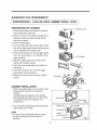
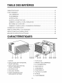
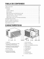
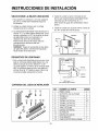
1. CABINET
2. HORIZONTAL AIR DEFLECTOR
(VERTICAL LOUVER)
3. VERTICAL AIR DEFLECTOR
(HORIZONTAL LOUVER)
4. AIR DISCHARGE
5. FRONT GRILLE
6. AiR INTAKE
(INLET GRILLE)
7. AIR FILTER
8. CONTROL BOARD
9. PC_¢¢ER CORD
10. EVAPORATO R
1I, CONDENSER
12. COMPRESSOR
13. BASE PAN
14, BRACE
15, REMOTE CONTROLLER
_2_

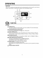
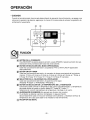
• CAUTION
When the air conditioner has been performing its cooling operation and is turned off or set to the fan
position, wait at least 3 minutes before resetting to the cooling operation again.
..........?........t
_ On
O O O
®
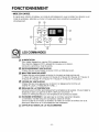
FUNCTION
POWER BUTTON
Toturn the air conditioner ON, push the button. Toturn the air conditioner OFF,push the button again.
This button takes priori_ over any other buttons.
OPERATION MODE SELECTION BUTTON
Every time you push this button, it will toggle COOL, FAN and DR"(.
ONIOFF TIMER BUTTON
Everytime you push this button, timer is set as follows.(1 Hour _ 2Hours _ 3Hours -) 4Hours
5Hours-_ 6Hours -) 7Hours-) 8Hours-t, 9Hours _ 10Hours-) 11Hours e, 12Hours @Cancel}
FAN SPEED SELECTOR
Everytime you push this button, it is set as follows. (Hil F3] _ Low[ F l] e, Med[ F2] -e Hi[F3].....)
ROOM TEMPERATURE SETTING BU_ON
This button can automatically _ntrol the temperature of the room.
The temperature can be set within a range of 60°F to 86°F by 1°E
Select the lower number for lower temperature of the room.
ENERGY SAVER (It is operated by only remote controllen)
The tan stops when the _mpressor stops _oling.
Approximately every 3 minutes the fan will turn on and check the room air to determine if cooling is
need_.
REMOCON SIGNAL RECEIVER
-3-

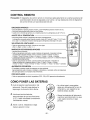
REMOTE CONTROLLER
Pir_aution: The Remote Controller will not function propedy if strong light strikes the sensor window
of the air conditioner or if there are obstacles between the Remote Controller and the air
conditioner,
, Toturn theair conditior.erON, pushthe I_Jtton.Toturn the air conditioner OFF,pushthe bu_onwain.
, Th_ bu_ontakes priorityov_ any other bu_ons.
• Whenyou first turn iton, theairconditioner [son the Highccolmod_ andthe temp.at 72°F(22°0).
TEMPERATURE SE_ING
• This button can automatically control the tem_rature e{ the room.
The temperature can be set within a range of _°F to 86°F by 1°F,(16°C to 30'C by 1°C)
Select the lower number for lower temperature o[ the room.
FAN SPEED
• EverytimeyoupushthisbuttonitMsset asfollows,{High(F3)-*Low(F1)-_Med(F2)-*High(F3).},
ON/OFF TIMER
- STOPPING OPERATION
• Eve_i_ you push th_ button, whenthe airconditioner is®eratJng,timer isset asfol_ows,
(1Hour-* 2Hours -*3Hours-* 4Hour-* 5Hours-4-6Hours---7Hours_8Hours -*9Hours-*
lOHours--,11Hours-* 12Hours_ Cancel)
• The Setting Tem_rature will _ rai_d by2_'F(1°C)30rain.later andby2°F(1°C) a_er another 30 min.
- STARTINGOPERATION
• Everyti_ you push th_ button,whenthe air cond_ionerisnot _erating, tier isset as Io[Iow.
(1Hour-* 2Hours -_3Hours_*4Hours_*5Hours_-6Hours _*7Hours- 8Hours_.9Hours_.
lOHours _.11Hours --.12Hours---CanceE}
ENERGY SAVER
• The fan sto_ when the compressor stops cooling_
Al@roximateiy every 3 minutes the fan will turn on and check the room air to determine if
cooling is needed_
MODE
• Eve_time you push this bu_ton,it wil_toggle between COOL, FAN and DRY.
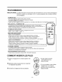
HOW TO INSERT BATTERIES
1. Remove the cover from the back of the remote controller.
2, Insert two batteries,
• Be sure that the (+) and (-) directions are correct.
• Be sure that both batteries are new,
3. Re-a_ach the cover,
Do not use rechargeable bat=
teries. Such batteries differ
from standard dry ceils in
shape, dimensions, and per-
folrmance.
Remove the batteries from
the remote controller if the air
conditioner is not going to be
used for an extended length
of time.

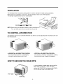
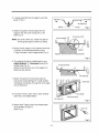
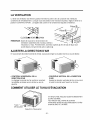
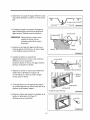
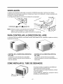
The ventilation lever must be CLOSE position in order to maintain the best cooling conditions.
When fresh air is necessary in the room, set the ventilation lever to the OPEN position.
The damper is opened and room air is exhausted.
Part
CLOSE|VENT|OPEN
NOTE: Before using the ventilation feature, make a ventilation kit
First, pull down part @ to horizontal line with part @.
TO CONTROL AIR DIRECTION
The direction of air can be controlted wherever you want to cool by adjusting the horizontal louver and
the vertical iouven
• HORIZONTAL AIR-DIRECTION CONTROL
The horizontal air direction is adjusted by
moving the vertical louver right or left.
• VERTICAL AIR-DIRECTION CONTROL
The vertical air direction is adjusted by rotating
the horizontal louver forward or backward.
HOW TO SECURE THE DRAIN PIPE
In humid weather, excess water may cause the
BASE PAN to ovediow. To drain the water,
remove the DRAIN CAP and secure the DRAIN
PIPE to the rear hoie of the BASE PAN
Drain pipe
Drain cap
-5-

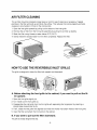
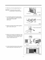
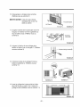
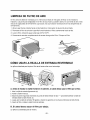
AIR FILTER CLEANING
The air filter should be checked at least twice a month to see if cleaning is necessary. Trapped
particles in the filter will build up and block the airflow. This reduces the cooling capacity and also
_uses an accumulation of frost on the cooling coils.
1. Open the inlet grille upward by pulling out the bottom of the inlet grille
2, Remove the air filter from the front grille assembly by pulling the air filter up slightly,
3. Wash the filter using lukewarm water below 40_(104_).
4, Gently shake the excess water from the filter completely. Repla_ the filter.
HOW TO USE THE REVERSIBLE INLET GRILLE
The grille is designed to caean the filter both upward and downward.
®
(a) (b)
A. Before attaching the front grille to the cabinet, if you want to pull out the fil-
ter upward;
1. Open the inlet grille slightly (a)
2. Turn inside out the front grille (a),
3. Disassemble the inlet grille from the front grille with separating the hinged part by inserting a
straight type screw-driver tip (b).
4. Then, rotate the inlet grille 180 degrees and insert the hooks into bottom holes of the front grille.
5. insert the filter and attach the front grille to the cabinet.
B. If you want to pull out the filter downward;
The griIle is already designed that way.
-6-

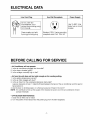
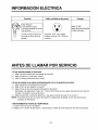
ELECTRICAL DATA
Line Cord Plug
Do not, under any
circumstances, cut or
remove the grounding prong
from the plug.
Power supply cord with
3-prong grounding plug
Use Wall Receptacle
Standard 125V, 3-wire grounding
receptacle rated 15A, 125V AC
Power Supply
Use 15 AMP, time
delay fuse or circuit
breaker.
BEFORE CALLING FOR SERVICE
• Air Conditioner will not operate.
1. Is the air conditioner plugged into the outlet?
2. Is the fuse or breaker good?
3. Is the voltage unusually high or low?
• Air from the unit does not feel cold enough on the cooling setting.
1. Is the setting temperature correct?
2. Is the air filter clogged with dust?
3. Is the air flow from the outside(condensers) obstructed?
Leave a clearance of over 1 meter(3.28 feet) between the back of the air conditioner and the wall or
fence behind it.
4. Are the door or windows open, or is there any source of heat in the room?
NOTE: If it is difficult to find out the cause of the trouble, be sure to turn the air conditioner off and
contact the dealer.
• OFF-SEASON MAINTENANCE
1. Clean the air filter and re-install.
2. Turn the power off and disconnect the power plug from the wall receptacle.

I
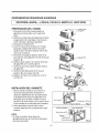
SELECT THE BEST LOCATION
1. To prevent vibration and noise, make sure the
unit is installed securely and firmly
2. Install the unit where the sunlight does not
shine directly on tlhe unit.
3. The outside of the _binet must extend
outward for at least 12" and there should be
no obstacles, such as a fence or wall, within
20" from the back of the cabinet because it will
prevent heat radiation of the condenser.
Restriction of outside air will greatly reduce
the cooling efficiency of the air conditioner.
CAUTION: All side louvers of the cabinet must
remain exposed to the outside of the structure.
WINDOW REQUIREMENTS
1, This unit is designed for installation in
standard double hung windows with actual
opening widths from 27" to 39",
The top and bottom window sash must open
sufficiently to allow a clear vertical opening of
16" from the bosom of the upper sash to the
window stool
INSTALLATION KITS CONTENTS
2. Install the unit a little slanted so the back is
slightly lower than the front(about i/2").
This will force condensed water to flow to the
outside,
3 Install the unit with the bottom about 30"_60"
above the floor level,
Fence
Cooled air
HeM
radiation
..............................................................
.....................Ov_20_.......................
%
Interior wail
235/8," rain
(Without frame curtain)
1,/2"to 11/4"
Exterior
NO, NAME OF PARTS,
1 FRAME CURTAIN 2
2 SILL SUPPORT 2
3 BOLT 2
4 NUT 2
5 SCREW(TYPE A) 16
6 SCREW(TYPE B) 3
7 SCREW(TYPE C) 5
8 FOAM-STRIP 1
9 FOAM-PE 1
10 UPPER GUIDE 1
11 FOAM-PE 1
12 FRAME GUIDE 2
13 WINDOW LOCKING BRACKET 1
-8-

SUGGESTED TOOL REQUIREMENTS
I SCREWDRIVER(+, -), RULLER, KNIFE, HAMMER, PENCIL,
LEVEL
PREPARATION OF CHASSIS
1. Remove the screws which fasten the cabinet
at both sides and at the back,_
2, Slide the unit from the cabinet by gripping the
base pan handle and pulling forward while
bracing the cabinet.
3. Remove EPS Material.
4. Cut the window sash seal to the proper length,
Peel off the backing and attach the foam-pe @
to the underside of the window sash,
5, Remove the backing from the top upper guide
Foam PE @ and a_ach it to the bottom of the
upper guide @,
6. Attach the upper guide onto the top of: the
cabinet with 3 type A screws,
7, insert the frame guides @ into the bottom of
the cabinet.
8. insert the Frame Curtain _') into the upper
guide @ and frame guides @.
9. Fasten the, curtains to the unit with 4 Type A
screws,
CABINET INSTALLATION
1. Open the window. Mark a line on center of the
window stool(or desired air conditioner
location).
Carefully place the cabinet on the window
stool and align the center mark on the bottom
front with the center line marked in the
window stool.
2. Pull the bottom window sash down behind the
upper guide until it meets.
"i Do not pull the window sash down so tiglhtly
that the movement of Frame Curtain is
restricted.
(Type
Shipping screws
EPS Matedal
(Type A)
Upper Guide
_Window stool
Front Angle Fig. 1
Foam-peQ
i_
Fig. 2

3. Loosely assemble the sill support using the
parts in Fig. 3.
4. Select the position that will place the sill
support near the outer most point on sill
(See Fig. 4)
NOTE: Be careful when you install the cabinet
(frame guides @ are broken so easily).
5. Attach the sill support to the cabinet track hole
in relation to the seiected position using
2 Type A screws in each support(See Fig. 4).
6 The cabinet should be installed with a very
slight tilt(about 1/2") downward toward the
outside (See Fig. 5),
Adjust the bolt and the nut of sill support for
baJancing the cabinet.
7, Attach the cabinet to the window stool by
driving the screws (_(Type B: Length sixteen
millimeters and below.) through the front angle
into window stool.
8. Pull each Frame curtain fully to each window
sash track, and repeat step 2.
9. Attach each Frame curtain the window sash
using screws ®(Type C).
(See Fig, 6)
Frame Guide @
IND_
Screw(Type A) @
• io ....
a r _i
Fig, 4
Screw(Type B)
Sill support
Sil_ suppod_
FrontAngle
_rew(Type B)
Fig. 5
Fig, 6

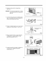
10. Slide the unit into the cabinet.(See Fig. 7)
CAUTION: For security purpose, reinstalU
screws(_pe A) at cabinet's sides.
11. Cut the foam-strip ® to the proper !ength
and insert between the upper window sash
and the lower window sash.
(See Fig. 8)
12, Attach the window locking bracket @with a
type C screw. (See Fig 9)
13. Attach the front grille to the cabinet by insert-
ing the tabs on the grille into the tabs on the
front of the cabinet, Push the grille in unti! it
snaps into place.(See Fig. 10)
14. Lift the in!et grille and secure it with a type A
screw through the front grille.(See Fig, 11)
Screw(Ty_ A)
......Power cord
/
Screw(Ty_ A) Fig. 7
Foam-StripQ
Fig, 8
locking bracket@
Fig. 9
Fig, 10 Fig, 11
Fig. 12

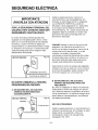
ELECTRICAL SAFETY
IMPORTANT
(PLEASE READ CAREFULLY)
FOR THE USER'S PERSONAL
SAFETY, THIS APPLIANCE MUST BE
PROPERLY GROUNDED
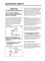
Because of potential safety hazards, we strongly
discourage the use of an adapter plug. However,
if you wish to use an adapter, a TEMPORARY
CONNECTION may be made. Use UL-listed
adapter, available from most local hardware
store(Fig. 14). The large slot in the adapter must
be aligned with the large slot in the receptacle to
assure a proper polarity connection.
The power cord of this appliance is equipped
with a three-prong(grounding) plug. Use this with
a standard three-slot(grounding) wall power
outlet(Fig. 13) to minimize the hazard of electric
shock. The customer should have the wall
receptacle and circuit checked by a qualified
electrician to make sure the receptacle is
properly grounded.
PREFERREDMETHOD
Fig. 13
DO NOT CUT OR REMOVE THE
THIRD(GROUND) PRONG FROM THE
POWER PLUG.
A. SITUATIONS WHERE THE APPLIANCE
WILL BE DISCONNECTED ONLY
OCCASIONALLY:
TEMPORARYMETHOD _ Fig. 14
Adapterplug-_ _1
I'_ Metalscrew
J Receptacle cover
CAUTION: Attaching the adapter ground terminal
to the wall receptacle cover screw does not
ground the appliance unless the cover screw is
metal, and not insulated, and the wall receptacle
is grounded through the house wiring.
The customer should have the circuit checked by
a qualified electrician to make sure the
receptacle is properly grounded.
Disconnect the power cord from the adapter,
using one hand on each. Otherwise, the adapter
ground terminal might break. DO NOT USE the
appliance with a broken adapter plug.
B. SITUATIONS WHERE THE APPLIANCE
WILL BE DISCONNECTED OFTEN.
Do not use an adapter plug in these situations.
Unplugging the power cord frequently can lead to
an eventual breakage of the ground terminal.
The wall power outlet should be replaced by a
three-slot(grounding) outlet instead.
USE OF EXTENSION CORDS
Because of potential safety hazards, we strongly
discourage the use of an extension cord.
However, if you wish to use an extension cord,
use a CSA certified/UL-listed 3-wire(grounding)
extension cord, rated 15A, 125V.
-12-

CARAOTER ISTIQU ES ................................................................................................................................... 13
FONCTIONNEMENT 14
LES COMMANDES ........................................................................................................................ 14
TELECOMMANDE ................................................................................................................... 15
LA VENTILATION ........................................................................................................................... 16
AJUSTER LA DIRECTION D'AIR ................................................................................................... 16
COMMENT UTILISER LE TUYAU D'EVACUATION ....................................................................... 16
NETTOYAGE DU FILTRE A AiR .......................................................................................................... 17
COMMENT UTILISER LA GRILLE D'ADMISSION REVERSIBLE .................................................. 17
DONNEES SUR L'ELECTRICITE ...................................................................................................... 18
AVANT DE FAIRE APPEL A UN TECHNICIEN .................................................................................. 18
INSTRUCTIONS POU R D'INSTALLATION ............................................................................................... 19
MESURES DE SECURITE ELECTRIQUES .......................................................................................... 23
t
1 BOTTLER
2_ DEFLECTEUR D'AIR HORIZONTAL
(VOLET VERTICAL)
3. DEFLECTEUR D'AIR VERTICAL
(VOLET HORIZONTAL)
4. DECHARGE D'AIR
5. GRILLAGE FRONTAL
6. PRISE D'ADMISSION D'AIR
(GRILLAGE DE LA PRISE)
7. FILTRE A AIR
8. PANNEAU DES COMMANDES
9. FIL D'ALIMENTATION
10. EVAPORATEUR
11. CONDENSEUR
12, COMPRESSEUR
13, PLATEAU DE LA BASE
14_ ATTACHE
15. TELECOMMANDE
_13-

• MISE EN GARDE
Si, apres avoir ut:ilis6 le climatiseur en mode de refroidissement, vous le mettez hors tension ou en
mode de ventilateur, attendez au moins 3 minutes avant de le remettre & la position de
refroidissement.
..................................................I
o o o
Dry _f _r
® o jo
LES COMMANDES
ALIMENTATION
Pour mettre t'appareil en marche (ON), pressez ce bouton.
Pour eteindre rappareil (OFF), pressez de nouveau sur le bouton.
Ce bouton a priorite sur tousles autres.
REFROIDISSEMENT/VENTILATEUR
Chaque lois que vous pressez ce bouton COOL et FAN altemeront
MINUTERIE MARCHE/ARRET
Chaque fois que vous pressez ce bouton la minutede se r¢gle comme suit.
(1 Heure -) 2 Heures @ 3 Heures @ 4 Heures -e 5 Heures _ 6 Heures .._ 7 Heures -e
8 Heures -) 9 Heures -e 10 Heures -e, 11 Heures _ 12 Heures -e annulation)
VITESSE DE VENTILATEUR
Chaque lois que vous appuyez sur ce bouton, le r6gUage se fait comme suit.
(Hi[F3] _ Low[F I] _ Med[F21 i_ Hi[F3]...}
REGLAGE DE LA TEMPERATURE
Ce bouton peut contr61er automatiquement la temperature de la piece. On peut regler la
temperature dans une gamme de 60°F a 86°F par tranche de l°R
Choisir un chiffre plus bas pour une temperature de la piece plus basse
ECONOMIE D'ENERGIE (11est opere par le contr61eur seulement eloigne.)
Le ventilateur s'arrete Iorsque le compressur cesse de refroidir.
Environ toutes les 3 minutes, le ventlateur se me_ra en marche et verifiera I'air de la
piece pour determiner si un refroidissement est necessaire.
CAPTEUR DU SIGNAL DE LA TELECOMMANDE
_14-

TELECOMMANDE
MISE EN GARDE: La telecommande ne fonctionnera pus correctement si une lumi ere forte frappe la
fen6tre du capteur du dlimatiseur ou s'il y adas obstacles entre ta tel6commande
et le climatiseur,
• Pour mettre ['appareil en marehe (ON), pre_z ce boulon.
Pour eteindre i'appareil (OFF), pressez de nouveau sur le _uton,
• Ce bouton a priodte sur teus les autres,
• Quand vous mettez I'appareilen marche fapremiere lois, iUest regle au mode High cool et & la tem_rature de 72°F(22C),
REGLAGE DE LA TEMPERATURE
• Ce bouton put contr6_erautomatiquement latemperature de la_ece On put regler _a
re.future dans une gamme de 60°F &86T par tranche de 1°F(160 & 300 par tranche de 1C).
Choisir un chiffre plus bus pour une tem_rature de la piece pius _sse.
VITESSE DE VENTILATEUR
• Chaquefoisquevo_sappuyezsur ce_u!on, le r6gla_ _ faircommesuit
{High(_2,)-*Low(z:z_Med(r: 2)-*High(f._)...}
MINUTERiE MARCHEIARRET
-ARR#_TDU FONCTIONNEMENT
• ChaqueIois quevous pressezce bout®, Ior_ue r_areil bnctionne, ]aminutede
ser_g_ecommesu_: (1 Heure--.2 Heures-_3Heures_4 Heures_5 Heures--*6Heures---
7 Heure_ 8 _ures.*9 Heures-.lO Heu[es-*l 1Heures-.12 Heures_.annulation)
• _ ternp6raturede reglageaugrnenterade2°F(1C) 30mnp_us_d etencorede2°F(1C) 30ranp}_star&
- D_BUT DU FONCTIONNEMENT
• Chaquelois quevous p_ssez ee bout®, Ior_ue ra_areil fonctionne, la minuteriese
reglecomme suit:(1 Heure_2 Heures_-3Heures_4 Heures_5 Heures_6 Heures-,.
7 Heures--*8 Heures-*9 Heures_*lo Heures--*lI Heures--*12Heures-.*annulatbn)
• Latem_rature de reghge augmenterade 2T(1 °C)30 mnplus tardet encore de2"F(1°C)30mn plus_rd,
ECONOMIE D'ENERGIE
• Le ventilateur s'arrete Iorsque le compressur cesc_ de refroidi_.
Environ toutestes3 minute& le ventlateur se mettra en marche et verifiera Fairde la piece pour
determiner si un reffoidisse_nt est necessaire,
REFROIDISSEMENT/VENTI LATEU R
• Chaque lois que vous pressezce bouton COOL, FAN et DRY altemeront.
COMMENT INSERER LES PILES
1.Retire la trappe pile en la faisant: glisser vers
bus.
2, Mette deux piles neuves duns leur Iogement
en respectant la polarite,
3, Remettre la trappe pile dans sa glissiere.
G
G
• Ne pas utiliser de piles
rechargeable dans la
t616commande.
• Si vous comptez ne pus utiliser
I'appareil pour une Iongue
p6riode, retirer les piles de la
t616commande.
-15-

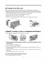
LA VENTILATION
Le levier de ventilation dolt 6tre en position ferm6eCCLOSE") afin de conserver les meilleures
conditions de refroidissement. Lorsque vous avez besion d'air frais dans la piece, reglez le levier & la
position OUVERTE("OPEN"). Le registre est ouvert et fair ambiant est expulse & Vext6rieur.
CLOSE -m- VENT_OpIEN
Piece
REMARQUE,: Avant de vous servir de la fonction de
ventilation rassemblez les morceaux derits A .....
I%ustration ci-haut. Premierement, ramenez ta piece @ vers le bas de fagon Ace
qu'elle fas.se une ligne droite avec la piece ®.
AJUSTER LA DIRECTION D'A,IR
En vous servant des ,_ltes horizontal et vertical, vous pouvez didger la circulation d'air I_ o0 vous le desirez.
• CONTROLE HORIZONTAL DE LA
DIRECTION D'AIR
Le reglage horizontal de I'air se fait en orientant
ies aile_es verticaies vers la droite ou vers la
gauche.
COMMENT
• CONTR_iLE VERTICAL DE LA DIRECTION
D'AIR
Ajustez la direction verti_le de I'air en tournant
le volet horizontal vers I'avant ou rarriere.
UTILISER LE TUYAU D'EVACUATION
Tuyau
d'evacuation _
Capuchon d'evacuation
En temp humide, l'eau peut _user le debordement
du BAC DE BASE.
Pour 6vacuer I'eau, enlevez le @u,_rcle
d'6vacuation et fixez le tuyau d'6vacuation _ rorifi_
arriere du BAC DE LA BASE.
-16-

NE OYAGE DU FILTRE A AIR
V6fif[ez le filtre & air au moins deux lois par mois afin de voir s'il doit 6tre nettoye. Les particules
empdsonn6es dans le fi]tre peuvent s'accumu]er et emp6cher la circulation d'a[r. Ceci r6duit s_fieusement
la capac[te de refroidissement et peut causer une accumulation de givre sur les serpentins du condenseur.
1. Ouverz le grillage d'admission vers le haut en tirant sur le has du grillage.
2. Retirez [e filtre & air du grillage en le tirant 16gerement vers le haut.
3. Nettoyez le filtre dans I'eau tiede, sous 40_(104°F)
4. Asisurez-vous de bien secouer le filtre et de retirer toute I'eau. Remettez le filtre en place.
COMMENT UTILISER LA GRILLE D'ADMISSlON REVERSIBLE
La grille est destinee a nettoyer le filtre a la lois vers le haut et vers le bas_
®
(a) (b) (c)
A. Avant d'a_acher ia grille frontale au boffier, si vous voulez r_resser le filtre
vers le haut;
1. Ouvfir la grille d'admission 16g_rement.(a)
2, Tourner I'interieur de la grille frontale.(a)
3, Demonter la grille d'amission de la grille frontaie en separant la piece articulee par I'insertion d'un
bout de tournevis,(b)
4. Ensuite, tourner la grille d'amission 180 degres et inserer ies crochets dans les trous de fond de la
grille frontale.
5, Inserer le filtre et attacher la grille frontale au bottler.
B. Si vous vouiez r_resser ie filtre vers le bas;
La grille est dej& destinee pour cette direction_
-17-

DONNEES SUR L'ELECTRICITE
Fichez du cordon d'alimentiation
Ne coupez ni
n'enlevez en aucun cas la
broche de mise a la masse
de la fiche.
Fil d'alimentation avec fiche
& 3 broches de type mise
& la masse
Utilisez ce type de prise murale
Receptacle standard de 125V & 3
ills avec mise a.la masse,
capacite, de 15A, 125V CA
Source d'alimentation
Utilisez un fusible
retardement de
15AMP ou un disjoncteur.
AVANT DE FAIRE APPE A UN TECHNICIEN
• Le climatiseur ne fonctionne pas.
1. Le climatiseur est-il branche dans la prise de courant?
2. Le fusible ou le disijoncteur est-il en parfait etat de marche?
3. Le courant est-il trop fort ou trop faible?
° L'air provenant du climatiseur n'est pas fraiche, m_me a la position de refroidissement.
1. Avez-vous regle le thermostat a. un niveau approprie?
2. Le filtre & air est-il sature de poussiere?
3. La circulation d'air provenant de I'exterieur(condenseurs) est-elle obstruee?
Laissez un espace libre d'environ 1 metre(3.28pi.) entre I'endos du climatiseur et le mur ou la
cl6ture situe derriere celui-ci.
4. Avez-vous oublie de refermer une porte ou une fen6tre; y a-t-il une source de chaleur dans la
piece?
REMARQUE: Si vous ne pouvez identifier la source du probleme, fermez le climatiseur et commu-
niquez avec votre marchand.
° Entretien hors saison
1. Nettoyez le filtre a.air et remettez-le en place.
2. Mettez I'appareil hors tension & I'aide de la touche des fonctions et debranchez le fil d'alimentation
de la prise de courant.
-18-

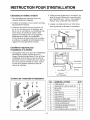
I ON POUR D'I
Choisissez le meilleur endroit
1. Afin d'empecher les vibrations et le bruit,
installez solidement I'appareil.
2. Installez le climatiseur l& oQ le soleil ne brillera
pas directement dessus.
3. L'exterieur du boftier doit sortir d'environ 12
po. et il ne doit pas y avoir d'obstacles, tels
qu'un tour ou une cleture, & une distance d'au
moins 20 po. de i'arriere du boitier; cede
distance minimale permet une propagation
adequate de la chaleur du condenseur.
Si vous bloquez le rayonnement de la chaleur
& I'exterieur, la capaite de refroidissement de
t'ap,pareil en sera grandement reduite
Conditions requises pour
I'installation a la fen tre
1. Cet appareil a et6 congu pour 6tre instafledans
des fenetres doubles & guillotine dont la
largeur d'ouverture vaire entre 27 po. et 39 po.
La glissiere de la fenetre du haut et celle du
bas doivent s'ouvrir suffisamment pour perme-
ttre une ouverture verticale de 16 po. a partir
du bas de la glissiere superieure jusqu'at
rebord de la fenetre+
Contenu de rensiemble d'installation
2:. Faites pencher 16gerement le climatiseur de
fagon & ce que I'arriere soit un peu plus bas
que I'avant(d'environ 1/2 po.). Ceci aidera
evacuer I'eau condensee vers i'exterieur.
3. Laissez une distance d'environ 30 a 60 po.
entre le plancher et la base du climatiseur.
Air refroidi
Suppod
Rayonnement
de la chaleur
1/2po.
Plus que 20 po,
CI6ture
i
+
/
,+
+
Denivellat:io,n
q2 a 11/4 po,
Exterieur
NO. NOMM DE LA PIECE Q;TE
1
2
3
4
5
6
7
8
9
10
11
12
13
TIGE-GUIDE 2
ANCRAGE DE L'APPUFFENETRE 2
BOULON 2
ECROU 2
VlS(TYPE A) 16
V!S(TYPE B) 3
VlS 5
BANDE DE MOUSSE 1
FIXATI_ DEMOUSSEDE_PE P'E 1
GUIDE ,SUPERIEUR 1
FIXATI_ DEMOUSSEDErfPE P'E 1
CADRAGE-GUIDE 2
POURLEVER_UIL_GE DE_ FENETRE 1
-19-

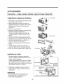
OUTILS SUGGERES
Tournevis(+, -), regle, couteau, marteau, crayon
et niveau bulle d'air
Preparatifs du ch&ssis du climatiseur
1. Retirez les vis qui retiennent: le boftier sur les
deux c6tes et par en arriere.
2. Glissez I'appareil emdehors du boi"tier en
agrippant la poignee du plateau de la base et
en le tirant vers I'avant, tout en le tenant
solidement,
3. Enlever le materiel EPS.
4. Decoupez la bande scellante du rebord de la
fenetre & la Iongueur appropriee.
Decollez I'endos et attachez la bande de
mousse de type PE ® sous le rebord de la
fenetre.
5, Enlever la bande de guide superieur bande
@, a_achez-le au fond de guide superieur @.
6. Joignez le guide superieur au-dessus du
boitier & I'aide de 3 vis de type A.
7. Inserez le cadrage-guide @ en-dessous du
bo_'tier.
8. Inserez les tige-guide O dans le guide
superieur @ et dans les cadrages-guide @
9. Faire fixer tige & la ch&ssis avec 4 type A vis.
Installation clu bottler
1, Ouvrez la fenetre. Faites une marque au
centre du rebord de la fenetre(ou ia o_ vous
voulez installer rappareil).
Placez soigneusement le boitier sur le reboid
de la fenetre et alignez la marque du centre
de la partie avant, sous le boi"tier, avec la ligne
centrale deja inscrite sur le rebord.
2, Des_ndez la glissiere du bas derriere le
guide superieur jusqu'a ce que les deux se
rencontrent.
• Ne descendez gas trop la glissiere de la
fenetre de fagion & ne pas bloquer le
mouvement de la tige-guide.
Vis en baleau
-- Materiel EPS
(TypeA)
iiiiiiiiiiiii!ii;;il¸;¸ ;i!!i ii!i;i¸¸¸ ;ii_! iiii_¸¸ ¸¸¸¸¸¸'¸
iiiiiiiiiiiii_ii:_;__ , ;iiiiiiiii_i_!i!'i_,ii_;il;_:i_';__ _
iiiii_,__' . _,....
iiii_;_--' i
Guide superi _ Re_rd de la fen6tre
Angle _or_tai Schema 1
Glissiere de la.. Guide superieur_
fer_tre I
Fixation de mousse @ I
de type pe I
Tige-gui
Fixation de mousse de a 2
20 -
La page est en cours de chargement...
La page est en cours de chargement...
La page est en cours de chargement...
La page est en cours de chargement...
La page est en cours de chargement...
La page est en cours de chargement...
La page est en cours de chargement...
La page est en cours de chargement...
La page est en cours de chargement...
La page est en cours de chargement...
La page est en cours de chargement...
La page est en cours de chargement...
La page est en cours de chargement...
La page est en cours de chargement...
La page est en cours de chargement...
-
 1
1
-
 2
2
-
 3
3
-
 4
4
-
 5
5
-
 6
6
-
 7
7
-
 8
8
-
 9
9
-
 10
10
-
 11
11
-
 12
12
-
 13
13
-
 14
14
-
 15
15
-
 16
16
-
 17
17
-
 18
18
-
 19
19
-
 20
20
-
 21
21
-
 22
22
-
 23
23
-
 24
24
-
 25
25
-
 26
26
-
 27
27
-
 28
28
-
 29
29
-
 30
30
-
 31
31
-
 32
32
-
 33
33
-
 34
34
-
 35
35


dans d''autres langues
- English: LG HBLG1200R Owner's manual
- español: LG HBLG1200R El manual del propietario
Documents connexes
-
Goldstar WG1200R Le manuel du propriétaire
-
Goldstar M1003R Le manuel du propriétaire
-
LG BAH-107 Le manuel du propriétaire
-
Goldstar WG1800R Le manuel du propriétaire
-
-
-
-
-
-