
PLEASE CONTACT US
BEFORE RETURNING
YOUR UNIT TO THE STORE
1-800-523-3987
www.sauder.com
Made in the USA
Archbold, OH
NOTE: THIS INSTRUCTION BOOKLET CONTAINS
IMPORTANT SAFETY INFORMATION.
PLEASE READ AND KEEP FOR FUTURE REFERENCE.
English .................... Page 1-19
Français ...............Pages 20-22
Espanol .............Páginas 23-25
Lot #: 351314 03 / 05 / 13
Date Purchased: ____________________
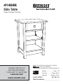
414686
Side Table
Original Cottage Collection

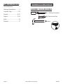
ASSEMBLY TOOLS REQUIRED
Hammer
No. 2 Phillips Screwdriver
Tip Shown Actual Size
ADULT ASSEMBLY REQUIRED
TABLE OF CONTENTS
Part Identifi cation .......................3
Hardware Identifi cation .............4
Assembly Steps ....................5-19
Français ..............................20-22
Espanol ...............................23-25
Safety .......................................26
Warranty ...................................27
Page 2 www.sauder.com/services 414686

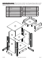
PART IDENTIFICATION: While not all parts are labeled, some of the parts will have a label or an inked
letter on the edge to help distinguish similar parts from each other. Use this PART IDENTIFICATION to help
identify similar parts.
A RIGHT END 1
B LEFT END 1
C TOP 1
D BOTTOM 1
E BACK 1
F ADJUSTABLE SHELF 1
G RIGHT FRONT/LEFT REAR LEG 2
H LEFT FRONT/RIGHT REAR LEG 2
I SKIRT 2
J DRAWER FRONT 1
K DRAWER FRONT MOLDING 1
L SIDE MOLDING 2
D110 DRAWER SIDE 2
D111 DRAWER BOX FRONT 2
D718 DRAWER BOTTOM 1
Page 3
www.sauder.com/services414686
A
B
C
D
E
F
G
H
I
J
K
L
D718
D110
D110
D111
D111
G
H
I
L

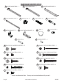
HARDWARE IDENTIFICATION
Screws are shown actual size. You may receive extra hardware with your unit.
Page 4 www.sauder.com/services 414686
RIGHT CABINET RAIL - 1
M
LEFT CABINET RAIL - 1
N O
RIGHT DRAWER SLIDE - 1
P
LEFT DRAWER SLIDE - 1 HIDDEN CAM - 22
1F
CAM SCREW - 12
8F
CAM DOWEL - 10
2F
BLACK 9/16" FLAT HEAD SCREW - 4
32S
KNOB - 1
61K
BLACK 9/16" LARGE HEAD SCREW - 12
1S
GOLD 5/16" FLAT HEAD SCREW - 4
3S
METAL PIN - 4
1R
METAL BRACKET - 2
4G
BLACK 1-5/8” PAN HEAD SCREW - 1
27S
BLACK 1-7/8" FLAT HEAD SCREW - 2
2S
BLACK 7/8" LARGE HEAD SCREW - 2
17S
RUBBER SLEEVE - 4
2R
BLACK 1-15/16" FLAT HEAD SCREW - 2
4S
19G
LARGE METAL BRACKET - 4
CAM COVER - 4
32P
SILVER 1/2" FLAT HEAD SCREW - 4
78S
BLACK 1-9/16" FLAT HEAD SCREW - 8
30S

Look for this icon. It means a video
assembly tip is available at:
www.sauder.com/services/tips
1
1
S
t
e
p
Page 5
www.sauder.com/services414686
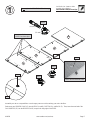
Assemble your unit on a carpeted fl oor or on the empty carton to avoid scratching your unit or the fl oor.
Push twenty-two HIDDEN CAMS (1F) into the ENDS (A and B), BOTTOM (D), and BACK (E). Then, insert the metal end of the
CAM DOWELS (2F) into the HIDDEN CAMS, except in the long edges of the ENDS.
Do not insert CAM
DOWELS into these edges.
Arrow
Hole
A
B
D
E
Do not tighten the HIDDEN CAMS in this step.
Insert the metal end of the CAM
DOWEL into the HIDDEN CAM.
Arrow
Arrow
1F
Arrow
1F
Arrow
(10 used)
(22 used)
1F
2F

2
2
S
t
e
p
Page 6 www.sauder.com/services 414686
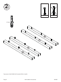
Turn twelve CAM SCREWS (8F) into the LEGS (G and H).
8F
(12 used)
H
H
G
G

3
3
S
t
e
p
Page 7
www.sauder.com/services414686
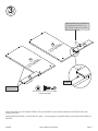
Turn four BLACK 9/16" FLAT HEAD SCREWS (32S) into the ENDS (A and B) until the shoulder of the SCREWS rest on the
surface of the ENDS.
Slide the SIDE MOLDINGS (L) onto the ENDS (A and B). Line up the groove in the MOLDINGS over the head of the SCREWS in
the ENDS.
These edges
should be even.
BLACK 9/16" FLAT HEAD SCREW
(4 used in this step)
32S
Shoulder
Apply pressure with your hands as
you guide the MOLDINGS over
the SCREWS and onto the ENDS.
L
L
A
B
Surface without
HIDDEN CAMS
Surface without
HIDDEN CAMS

4
4
S
t
e
p
Page 8 www.sauder.com/services 414686
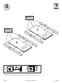
Fasten the LEGS (G and H) to the ENDS (A and B). Tighten twelve HIDDEN CAMS.
A
B
Surface with
HIDDEN
CAMS
Surface with
HIDDEN
CAMS
G
H
G
H
These edges
should be even.
These edges
should be even.

5
5
S
t
e
p
Page 9
www.sauder.com/services414686
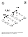
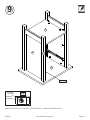
Fasten the CABINET RAILS (M and N) to the ENDS (A and B). Use four GOLD 5/16" FLAT HEAD SCREWS (3S).
NOTE: The CABINET RAILS are marked “CR” and “CL” for easy identification.
A
B
G
H
Roller end
Roller end
M
N
GOLD 5/16" FLAT HEAD SCREW
(4 used in this step)
3S

Fasten the LEFT END (B) to the TOP (C). Tighten two HIDDEN CAMS.
6
6
S
t
e
p
Page 10 www.sauder.com/services 414686
Caution
Risk of damage or
injury. Hidden Cams
must be completely
tightened. Hidden
Cams that are not
completely tightened
may loosen, and parts
may separate.
To completely tighten:
Start Tighten
Arrow
Arrow
Maximum
210 degrees
Minimum
190 degrees
B
H
C
Surface with holes
Surface with
HIDDEN CAMS
Roller end
These holes
must be here.

7
7
S
t
e
p
Page 11
www.sauder.com/services414686
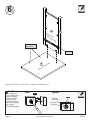
Fasten the BACK (E) to the TOP (C). Tighten two HIDDEN CAMS.
Maximum
210 degrees
Minimum
190 degrees
Arrow
C
E
Surface with
HIDDEN CAMS

8
8
S
t
e
p
Page 12 www.sauder.com/services 414686
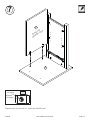
Fasten the BOTTOM (D) to the LEFT END (B). Tighten two HIDDEN CAMS.
Fasten the BOTTOM (D) to the BACK (E). Use two BLACK 1-7/8" FLAT HEAD SCREWS (2S).
Maximum
210 degrees
Minimum
190 degrees
Arrow
E
B
D
Surface with
HIDDEN CAMS
BLACK 1-7/8" FLAT HEAD SCREW
(2 used in this step)
2S

9
9
S
t
e
p
Page 13
www.sauder.com/services414686
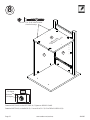
Fasten the RIGHT END (A) to the TOP (C) and BOTTOM (D). Tighten four HIDDEN CAMS.
Maximum
210 degrees
Minimum
190 degrees
Arrow
D
A
C
G
Roller end

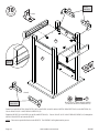
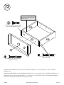
Fasten four LARGE METAL BRACKETS (19G) to the ENDS (A and B) and two METAL BRACKETS (4G) to the BOTTOM (D).
Use six BLACK 9/16" LARGE HEAD SCREWS (1S).
Fasten the SKIRTS (I) to the ENDS (A and B) and BOTTOM (D). Use six BLACK 9/16" LARGE HEAD SCREWS (1S) through the
METAL BRACKETS and into the SKIRTS.
NOTE: There are no pre-drilled holes in the SKIRTS. The SCREWS will tighten into the groove.
10
10
S
t
e
p
Page 14 www.sauder.com/services 414686
D
A
B
I
I
Use this
groove.
BLACK 9/16" LARGE HEAD SCREW
(12 used for the METAL BRACKETS)
1S
4G
4G
19G
19G
(2 used)
(4 used)
19G
19G
Use the
center hole.
Use the
center hole.

11
11
S
t
e
p
Page 15
www.sauder.com/services414686
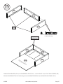
Fasten the DRAWER SIDES (D110) to a DRAWER BOX FRONT (D111). Use four BLACK 1-9/16" FLAT HEAD SCREWS (30S).
Slide the DRAWER BOTTOM (D718) into the grooves in the DRAWER SIDES (D110) and DRAWER BOX FRONT (D111).
Groove
D111
D110
D110
Finished surface
D718
These edges
should be even.
D111
D110
D110
BLACK 1-9/16" FLAT HEAD SCREW
(4 used in this step)
30S

Fasten the DRAWER FRONT MOLDING (K) to the DRAWER FRONT (J). Use two BLACK 1-15/16" FLAT HEAD SCREWS (4S).
12
12
S
t
e
p
Page 16 www.sauder.com/services 414686
BLACK 1-15/16" FLAT HEAD SCREW
(2 used in this step)
4S
K
J
Surface with
fewer holes

13
13
S
t
e
p
Page 17
www.sauder.com/services414686
Fasten the other DRAWER BOX FRONT (D111) to the DRAWER SIDES (D110). Use four BLACK 1-9/16" FLAT HEAD
SCREWS (30S).
Fasten the DRAWER FRONT (J) to the DRAWER BOX FRONT (D111). Use two BLACK 7/8" LARGE HEAD SCREWS (17S).
Fasten the KNOB (61K) to the DRAWER FRONT (J). Use a BLACK 1-5/8" PAN HEAD SCREW (27S) through the DRAWER
BOX FRONT, through the DRAWER FRONT, and into the KNOB.
Be sure the DRAWER BOTTOM
inserts into the DRAWER BOX
FRONT groove.
BLACK 7/8" LARGE HEAD SCREW
(2 used for the DRAWER FRONT)
17S
J
61K
BLACK 1-5/8” PAN HEAD SCREW
(1 used for the KNOB)
27S
D111
D110
D110
BLACK 1-9/16" FLAT HEAD SCREW
(4 used in this step)
30S

14
14
S
t
e
p
Page 18 www.sauder.com/services 414686
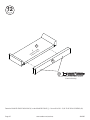
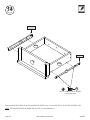
Fasten the DRAWER SLIDES (O and P) to the DRAWER SIDES (D110). Use four SILVER 1/2" FLAT HEAD SCREWS (78S).
NOTE: The DRAWER SLIDES are marked “DR” and “DL” for easy identification.
D110
D110
Roller end
Roller end
O
P
SILVER 1/2" FLAT HEAD SCREW
(4 used in this step)
78S

15
15
S
t
e
p
Page 19
www.sauder.com/services414686
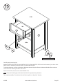
Carefully stand your unit upright.
Push the RUBBER SLEEVES (2R) over the METAL PINS (1R). Insert the METAL PINS into the hole locations of your choice in the
ENDS (A and B). Set the ADJUSTABLE SHELF (F) onto the METAL PINS.
To insert the drawer into your unit, tip the front of the drawer down and drop the rollers on the drawer behind the rollers on the unit.
Lift the front of the drawer up and slide it into the unit.
Push a CAM COVER (32P) onto each visible HIDDEN CAM.
NOTE: Please read the back pages of the instruction booklet for important safety information.
This completes assembly. Clean with your favorite furniture polish or a damp cloth. Wipe dry.
(4 used)
A
B
F
To cover HIDDEN CAMS
(4 used)
32P
40 lbs.
20 lbs.
25 lbs.
7 lbs.
1R
2R

A l’usage exclusif du
Canada Noter la date
d’achat de cet élément
et conserver le livret
pour future référence.
Pour contacter Sauder
en ce qui concerne cet
élément, faire référence
au numéro de lot et
numéro de modèle en
appelant notre numéro
sans frais.
Lot nº : ____________
Date de
l’achat: ____________
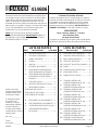
LISTE DE PIÈCES
REFERENCE DESCRIPTION QUANTITÉ
LISTE DE PIÈCES
REFERENCE DESCRIPTION QUANTITÉ
NOUS SOMMES LA POUR VOUS AIDER!
Nous faisons de notre mieux pour nous assurer que
votre meuble arrive dans d’excellentes conditions. Nos
représentants du service Clientèle sont aimables et prêts
à vous aider au cas où une pièce aurait été endommagée
ou manquerait (ou si vous aviez besoin d’aide pour
l’assemblage). NE RAMENEZ PAS LE MEUBLE AU
MAGASIN. Au Canada, composez ce numéro d’appel gratuit:
1-800-523-3987
Du lundi au vendredi, de 9 heures du matin à
5:30 heures du soir (horaire Côte Est)
(sauf jours fériés)
Si une pièce a besoin d’être remplacée, la pièce de
remplacement sera envoyée dans les 48 heures. (Sauf
week-ends et jours fériés)
Utilisez les instructions d’assemblage en français avec
les schémas étape par étape du manuel d’instruction
en anglais. Chaque étape en français correspond à la
même étape en anglais. La pièce devant être attachée
à l’élément est représentée en gris sur les schémas de
chaque étape pour plus de précision. Comparer la “Liste
de pièces” ci-dessous avec la “PART IDENTIFICATION”
du manuel en anglais pour vous familiariser avec les
pièces avant l’assemblage.
REMARQUE : CE MANUEL D’INSTRUCTIONS
CONTIENT D’IMPORTANTES INFORMATIONS
RELATIVES À LA SÉCURITÉ. À LIRE ET CONSERVER
POUR TOUTE RÉFÉRENCE FUTURE.
M
GLISSIÈRE DROITE D'ÉLÉMENT
........1
N
GLISSIÈRE GAUCHE D'ÉLÉMENT
......1
O COULISSE DROITE DE TIROIR .....1
P
COULISSE GAUCHE DE TIROIR
.........1
1F
EXCENTRIQUE ESCAMOTABLE
.......22
2F CHEVILLE D'EXCENTRIQUE .......10
8F VIS D'EXCENTRIQUE ...................12
4G CONSOLE EN MÉTAL .....................2
19G
GRANDE CONSOLE EN MÉTA
L ..........4
61K BOUTON ..........................................1
32P COUVERCLE D'EXCENTRIQUE ....4
1R GOUPILLE EN MÉTAL ....................4
2R MANCHON EN CAOUTCHOUC ......4
1S VIS TÊTE LARGE 14 mm NOIRE ..12
2S VIS TÊTE PLATE 48 mm NOIRE .....2
3S VIS TÊTE PLATE 8 mm DORÉE .....4
4S VIS TÊTE PLATE 49 mm NOIRE .....2
17S VIS TÊTE LARGE 22 mm NOIRE ....2
27S VIS TÊTE GOUTTE DE
SUIF 41 mm NOIRE.........................1
30S VIS TÊTE PLATE 40 mm NOIRE .....8
32S VIS TÊTE PLATE 14 mm NOIRE .....4
78S
VIS TÊTE PLATE 13 mm
ARGENTÉE
.4
A EXTRÉMITÉ DROITE ......................1
B EXTRÉMITÉ GAUCHE ....................1
C DESSUS ..........................................1
D DESSOUS .......................................1
E ARRIÈRE .........................................1
F TABLETTE RÉGLABLE ...................1
G PIED AVANT DROIT/
ARRIÈRE GAUCHE .........................2
H PIED AVANT GAUCHE/
ARRIÈRE DROIT .............................2
I PLINTHE ..........................................2
J DEVANT DE TIROIR ........................1
K MOULURE DE DEVANT
DE TIROIR .......................................1
L MOULURE LATÉRALE ....................2
D110 CÔTÉ DE TIROIR ...........................2
D111 DEVANT DE CAISSON
DE TIROIR .......................................2
D718 FOND DE TIROIR ...........................1
Bout de canapé414686
Page 20 www.sauder.com/services 414686
La page est en cours de chargement...
La page est en cours de chargement...
La page est en cours de chargement...
La page est en cours de chargement...
La page est en cours de chargement...
La page est en cours de chargement...
La page est en cours de chargement...
La page est en cours de chargement...
-
 1
1
-
 2
2
-
 3
3
-
 4
4
-
 5
5
-
 6
6
-
 7
7
-
 8
8
-
 9
9
-
 10
10
-
 11
11
-
 12
12
-
 13
13
-
 14
14
-
 15
15
-
 16
16
-
 17
17
-
 18
18
-
 19
19
-
 20
20
-
 21
21
-
 22
22
-
 23
23
-
 24
24
-
 25
25
-
 26
26
-
 27
27
-
 28
28


Sauder 414686 Manuel utilisateur
- Taper
- Manuel utilisateur
- Ce manuel convient également à
dans d''autres langues
- English: Sauder 414686 User manual
- español: Sauder 414686 Manual de usuario
Documents connexes
-
Sauder 412301 Mode d'emploi
-
-
-
-
-
-
-
-
-