Tractel blocstop BSO 1000 Series Original Operation And Installation Manual
- Taper
- Original Operation And Installation Manual

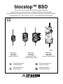
blocstop™ BSO
Fall arrest device for suspended material-lifting and rigging installations
Fangvorrichtung für hochziehbare Personen- und Materialaufnahmemittel (PAM & MAM)
Dispositif antichute pour plateformes suspendues pour levage de personnens et matériel (PSLP & PSLM)
Opvangvoorziening voor omhoog trekbare personen- en materiaalhefmiddelen (PAM & MAM)
Model series /
Typenreihe /
Série / Serie
blocstop™ BSO 500
Model series /
Typenreihe /
Série / Serie
blocstop™ BSO 1000
blocstop™ BSO 1000 EFA
Model series /
Typenreihe /
Série / Serie
blocstop™ BSO 2050/2360
Original Operation and
Installation Manual
Manuel d´installation et de
manutention original
Original-Montage- und
Betriebsanleitung
Originele montage- en
bedieningshandleiding
Tractel Greifzug GmbH

blocstop™ BSO
EN-DE-FR-NL-II G905.11 - 01/2016
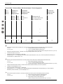
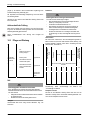
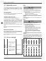
Technical Data / Technische Daten / Données techniques / Technische gegevens
Type
3) 4) 5)
Typ
3) 4) 5)
Type
3) 4) 5)
Type
3) 4) 5)
Capacity in t
Tragfähigkeit in t
Capacité in t
Draagvermogen in t
Wire rope specification
Seilspezifikation
Spécification du câble
Kabelspecificatie
Bolt-Ø in mm
2)
Bolzen-Ø in mm
2)
Diamètre des axes
2)
Bout-Ø in mm
2)
Persons
Personen
Personnes
Personen
Material
Material
Materiel
Materiaal
Ø in mm
Ø in mm
Ø du câble en mm
Ø in mm
Minimum tensile strength in kN
Mindestbruchkraft in kN
Force minimal de rupture en kN
Minimum breukkracht in kN
BSO 510 — 0,35 6 13,7
1b)
12
BSO 500 0,6 0,6 8 47,1
1a)
BSO 520 0,6 0,6 9 47,1
1a)
BSO 1000 0,7 0,7 8 54,9
1a)
BSO 1020 0,8 0,8 9 62,8
1a)
BSO 1030 1,0 1,0 10 78,5
1a)
BSO 1040 1,0 1,0 11,5 78,5
1a)
BSO 1000 EFA 0,7 0,7 8 54,9
1a)
BSO 1020 EFA 0,8 0,8 9 62,8
1a)
BSO 1030 EFA 1,0 1,0 10 78,5
1a)
BSO 1040 EFA 1,0 1,0 11,5 78,5
1a)
BSO 2050 2,0 2,6 14 157,0
1a)
22
BSO 2360 2,3 3,0 16 180,5
1a)
Table/Tabelle/Tableau/Tabel 1
1)
Calculation of the required minimum breaking load F
o
of the rope (does not correspond to the actual, manufacturer-specific minimum breaking load!)
F
o
= Z
p
x S
F
o
= a) 8 / b) 5 x S
F
o
: smallest guaranteed breaking load of the wire rope [N]
Z
p
: = a) 8 / b) 5: Calculated coefficient of steel wire rope
S: maximum static load on the wire rope [N] (maximum working load of the hoist, 1 kg = 9.81 N)
2)
Strength of the bolt material: 800 N/mm
2
800 MPa. Do not use high-strength galvanised screws (10.9 or 12.9).
3)
For hoists with a speed of up to 18 m/min
4)
optionally with limit switch: Identification E (e. g. BSO 500 E)
5)
Temperature range: -25 – +70 °C, depending on the ambient conditions (ambient temperature, sunrays, etc.) as well as the possible thermal discharge (dirt,
accumulated heat, etc.). Relative humidity < 75 %
1)
Berechnung der erforderlichen Mindestbruchkraft F
o
des Seiles (entspricht nicht der tatsächlichen, herstellerspezifischen Mindestbruchkraft!)
F
o
= Z
p
x S
F
o
= a) 8 / b) 5 x S
F
o
: kleinste garantierte Bruchlast des Drahtseils [N]
Z
p
: = a) 8 / b) 5: Ausnutzungskoeffizient des Drahtseils
S: maximale statische Zuglast im Drahtseil [N] (maximale Betriebslast der Winde, 1 kg = 9,81 N)
2)
Festigkeit des Bolzenwerkstoffes: 800 N/mm
2
800 MPa. Keine hochfesten verzinkten Schrauben (10.9 oder 12.9) verwenden.
3)
Für Winden mit Geschwindigkeit bis 18 m/min
4)
optional mit Endschalter: Kennzeichnung E (z. B. BSO 500 E)
5)
Temperaturbereich: -25 – +70 °C, abhängig von den Umgebungsbedingungen (Umgebungstemperatur, Sonneneinstrahlung, etc.) sowie der möglichen
Wärmeabfuhr (Schmutz, Stauwärme, etc.). Rel. Luftfeuchtigkeit < 75 %
1)
Calcul de l’effort de rupture mininal requis F
o
du câble (ne correspond pas à l’effort de rupture minimal effectif et spécifique du fabricant!) :
F
o
= Z
p
x S
F
o
= a) 8 / b) 5 x S
F
o
: Charge de rupture minimale garantie du câble métallique [N]
Z
p
: = a) 8 / b) 5: Coefficient d’utilisation du câble métallique
S: Charge statique maximale du câble métallique [N]
(capacité de charge maximale de fonctionnement du treuil, 1 kg = 9,81 N)

blocstop™ BSO
G905.11 - 01/2016 EN-DE-FR-NL-III
2)
Résistance du matériau de boulon : 800 N/mm
2
800 MPa. Ne pas utiliser de boulons galvanisés haute résistance (10.9 ou 12.9).
3)
Pour les treuils d'une vitesse jusqu'à 18 m/min
4)
en option avec fins de course : Marquage E (par exemple BSO 500 E)
5)
Plage de température: -25 – +70 °C, en fonction des conditions ambiantes (température ambiante, exposition à la lumière du soleil, etc.) et de l'évacuation de la
chaleur possible sur le site (saleté, accumulation de chaleur, etc.) Humidité relative de l'air < 75
1)
Berekening van de minimum breukkracht F
o
van de kabel (komt niet overeen met de daadwerkelijke fabrikantspecifieke min. breukkracht!)
F
o
= Z
p
x S
F
o
= a) 8 / b) 5 x S
F
o
: kleinste gegarandeerde breuklast van de draadkabel [N]
Z
p
: = a) 8 / b) 5: Belastingscoëfficiënt van de draadkabel
S: maximale statische treklast in draadkabel [N]
(maximale bedrijfslast van de lier, 1 kg = 9,81 N)
2)
Sterkte van het boutenmateriaal: 800 N/mm
2
800 MPa. Gebruik geen extra sterke verzinkte bouten (10.9 of 12.9).
3)
Voor lieren met een snelheid tot 18 m/min
4)
optioneel met eindschakelaar: Markering E (bijv. BSO 500 E)
5)
Temperatuurbereik: -25 – +70 °C, afhankelijk van de omgevingsfactoren (omgevingstemperatuur, zonnestraling etc.) en van de mogelijke warmteafvoer (vuil,
warmtestuwing etc.). Rel. luchtvochtigheid < 75 %
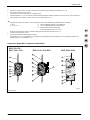
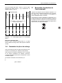
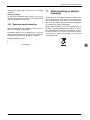
Components / Bestandteile / Composants / Bestanddelen
OUVRIR
OPEN
AUF
ZU
CLOSE
FERMER
ZU
CLOSE
FERMER
BSO 2050BSO 1000–1040 EFA –2360
BSO 500–520
BSO 1020–1040
OUVRIR
OPEN
AUF
ZU
CLOSE
FERMER
00322/1
9
Fig./Abb./Fig./Afb. 1

blocstop™ BSO
EN-DE-FR-NL-IV G905.11 - 01/2016
00324/1
e
Ø h
b
c
1
g
a
c
2
d
1
d
2
f
e
Ø h
b
c
1
g
a
c
2
d
1
b
1
d
2
a
ef
g
Ø h
b
c
1
c
2
c
3
d
1
d
2
a
1
Fig./Abb./Fig./Afb. 2
Measure in mm / Maß in mm / Mesure en mm / Maat in mm
a a
1
b b
1
c
1
c
2
c
3
d
1
d
2
e f g Ø h
BSO 500/510/520 214 — 121 — 131 40 — 64 20 40 12,5 21,5 12,2
BSO 1020/1030/1040 251 — 140 — 131 40 — 65 20 56 12,5 21,5 12,2
BSO 1000 EFA/
1020 EFA/1030 EFA/
1040 EFA
251 — 140 45 131 40 — 65 20 56 12,5 21,5 12,2
BSO 2050/2360 409 70 150 — 183 110 55 60 27,5 35 60 36 22,2
Table/Tabelle/Tableau/Tabel 2

blocstop™ BSO
G905.11 - 01/2016 EN-DE-FR-NL-V
Fig./Abb./Fig./Afb. 3
Fig./Abb./Fig./Afb. 4
00328/0
Fig./Abb./Fig./Afb. 5
Fig./Abb./Fig./Afb. 6
Fig./Abb./Fig./Afb. 7
Fig./Abb./Fig./Afb. 8
vn

blocstop™ BSO
EN-DE-FR-NL-VI G905.11 - 01/2016
00302/0
3
1
2
ZU
CLOSE
FERMER
ZU
CLOSE
FERMER
OUVRIR
OPEN
AUF
Fig./Abb./Fig./Afb. 9
00323/0
1
6
4
3
5
7
2
Fig./Abb./Fig./Afb. 10
00329/
1
OUVRIR
OPEN
AUF
ZU
CLOSE
FERMER
ZU
CLOSE
FERMER
OUVRIR
OPEN
AUF
ZU
CLOSE
FERMER
ZU
CLOSE
FERMER
B
B
A
A
Fig./Abb./Fig./Afb. 11
Fig./Abb./Fig./Afb. 12

blocstop™ BSO
G905.11 - 01/2016 EN-DE-FR-NL-VII
00345/1
BU
BKBN
BKWH
GNYE
CA3LS
1 - BK
2 - BKWH
Fig./Abb./Fig./Afb. 13
00851/0
CA3LS
BSO…EFA
1
2
3 - 1
4 (PE) - 2
Fig./Abb./Fig./Afb. 14

blocstop™ BSO
EN-DE-FR-NL-VIII G905.11 - 01/2016

Installation and operating manual
G905.11 - 01/2015 EN-1
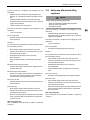
Contents
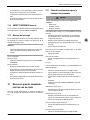
1 General ............................................................................... 2
1.1 Terms and abbreviations used in this manual .......... 2
1.2 Symbols used in this manual .................................... 3
2 Safety .................................................................................. 3
2.1 General safety instructions ....................................... 3
2.2 Instructions for the operator ...................................... 4
2.3 System manufacturer's responsibilities ..................... 4
3 Overview ............................................................................. 5
3.1 Delivery state ............................................................ 5
3.2 Scope of delivery ...................................................... 5
3.3 Equipment description .............................................. 5
4 Description ......................................................................... 6
4.1 Functional description ............................................... 6
4.2 Components / Modules ............................................. 7
4.3 Technical Specifications ........................................... 7
4.4 Operating fluids ......................................................... 7
4.5 Circuit diagram .......................................................... 7
4.6 Safety equipment ...................................................... 7
4.7 Anchoring .................................................................. 8
5 Ropes .................................................................................. 8
6 Optional accessories ......................................................... 8
7 Options ............................................................................... 8
8 Model versions ................................................................... 8
9 Necessary accessories ..................................................... 8
10 Installation and commissioning ....................................... 8
10.1 Directives and standards .......................................... 8
10.2 Checks to be undertaken before
starting installation .................................................... 8
10.3 Assembly .................................................................. 9
10.4 Commissioning ....................................................... 10
11 Operation .......................................................................... 11
11.1 Checking before starting work ................................ 11
11.2 Operation with man riding equipment ..................... 11
11.3 Operation with material lifting equipment ................ 12
11.4 Manual SAFETY-STOP .......................................... 12
11.5 Securing the load .................................................... 12
12 Immediate measures after a safety-stop ....................... 12
12.1 Safety-stop when using man riding equipment ....... 12
12.2 Safety-stop with material lifting equipment ............. 13
12.3 Measures to be taken after a problem
or safety-stop .......................................................... 14
13 Foreseeable misuse ......................................................... 14
14 Dismantling ....................................................................... 14
15 Transport and storage ..................................................... 15
15.1 Transport ................................................................. 15
15.2 Storage .................................................................... 15
16 Maintenance work ............................................................ 15
16.1 Authorized maintenance personnel ......................... 15
16.2 Mandatory inspections ............................................. 15
16.3 Care and maintenance ............................................ 15
16.4 Ordering spare parts ................................................ 16
17 Disposal and environmental protection ......................... 16
18 Troubleshooting ............................................................... 17
19 EU Declaration of Conformity (Extract) .......................... 18
19.1 Fall arrest device for transport of persons ............... 18
19.2 Fall arrest device for transport of materials ............. 20
DANGER!
Risk of injury caused by falling objects, malfunctions,
incorrect usage and incorrect operation!
Failure to follow these instructions:
can result in severe injuries or death,
can result in damage to the equipment.
– Read through this operating manual carefully before you
install and commission this machine.
– Follow the instructions and procedures specified in this
manual in order to ensure safe operation of the equip-
ment.

Installation and operating manual
EN-2 G905.11 - 01/2015
1 General
Copyright
The copyright of this instruction manual remains with TRACTEL
Greifzug GmbH.
This instruction manual is intended only for the operators of the
systems described here and their staff. This instruction manual
must be available to the operating personnel at all times. Addi-
tional copies can be obtained on request.
No part of this instruction manual may be reproduced, distributed
or otherwise communicated without the permission of TRACTEL
Greifzug GmbH.
Legal proceedings may be implemented in the case of any in-
fringements.
Manufacturer's address
Sales and service office:
TRACTEL Greifzug GmbH
Scheidtbachstraße 19-21
51469 Bergisch Gladbach, Germany
Postfach 20 04 40
51434 Bergisch Gladbach, Germany
Tel: +49 (0) 22 02 / 10 04-0
Fax: +49 (0) 22 02 / 10 04-50 + 70
TRACTEL Greifzug GmbH reserves the right to make changes to
the product described in this instruction manual as part of their
ongoing product improvement programme.
Customers can obtain documentation about other TRACTEL
products by requesting the documentation from companies within
the TRACTEL Group or service organizations appointed by the
TRACTEL Group. Please visit our TRACTEL website at:
www.tractel.com for further details regarding the hoisting gear
and related accessories; stationary or mobile working platforms
for moving around on the inside and outside of buildings; rigging;
block stops for heavy loads; personal safety harnesses to pre-
vent falls; traction and rope tension measuring equipment, etc.
The TRACTEL Group and its dealer network also provide addi-
tional customer and repair services upon request.
1.1 Terms and abbreviations used in
this manual
The terms used in this instruction manual have the following
meanings:
System / Machine
Pursuant to the Machine Directive 2006/42/EC lifting equipment,
hoisting gear, safety equipment and rigging for lifting are regard-
ed as machines. The term "system" or "machine" also describes
the device in which the unit described here will be fitted.
System manufacturer
The system manufacturer (system planner, system manufacturer,
installer) is the company marketing the system and all of the
required components. The system manufacturer is responsible
for the design, manufacturing, assembly and marketing.
Rigging
Rigging consists of equipment which does not belong to the
hoisting gear and which creates a connection between the carry-
ing means and the load or the carrying means and the load lifting
equipment (e.g. rope loops, round slings, shackles, swivel hooks,
eye hooks, deflection rollers).
Anchoring point
Part of the on-site suspended construction to which the suspen-
sion rope, the safety rope, deflection rollers and the hoisting gear
are anchored separately.
Actuation
The fall arrest device is triggered (safety stop situation) by man-
ual actuation or uncontrolled actuation resulting from vibrations.
Operating personnel
Personnel who have been trained by the operator to operate the
product and are authorized to operate it.
Operating personnel (man riding equipment)
An appointed person who has undergone the appropriate ad-
vanced training for working at heights and who, due to his
knowledge and practical experience, is in the position to perform
the required operating tasks when provided with the necessary
instructions.
Operator
The operator is responsible for the correct operation of the sys-
tem / equipment and also for adhering to the maintenance inter-
vals and the undertaking of the service work.
Running hours
The running hours are the effective operating times of a hoist's
motor.
Electrician
An electrician is someone who possesses sufficient knowledge
or has obtained the required qualification through training in
order to recognize the risks and avoid the dangers that can occur
when working with electricity.
SAFETY-STOP
The fall arrest device is triggered (safety stop situation, e.g.
overspeed) in the event of a suspension cable rupture or a hoist
malfunction.
Fall arrest device
A device for stopping the load lifting equipment in the event of
the suspension rope snapping or a malfunction, e.g. drive mal-
function.
Overall suspended load
The overall suspended load is the actual suspended static load,
which is made up of the payload, the load lifting equipment's own
weight, the additional fittings, the wire ropes and the control and
connection cables.

Installation and operating manual
G905.11 - 01/2015 EN-3
Hoisting gear / machine for lifting loads
Device or equipment consisting of a device with load carrying
means for lifting or transporting loads (e.g. wire rope hoist or wire
rope hoist with rope and swivel hook).
Customer / end customer
The customer or end customer is the system manufacturer's
customer and can also be the operator.
Load lifting equipment
A component or piece of equipment which does not belong to the
hoisting gear, which enables the load to be grasped and which is
attached between the machine and the load or to the load itself,
or is intended to be an integral component of the load. Rigging
and its components are also regarded as load lifting equipment.
Material lifting equipment
Load lifting equipment for material.
Maximum working load
The maximum working load specifies the maximum load the
device is allowed to bear.
Payload
The payload is the load that is raised, pulled or held in place by
the device.
Man riding equipment
Lifting equipment for persons. Combined material and man riding
equipment also counts here.
Specialist
An appointed person who has undergone the appropriate training
and who, due to his knowledge and practical experience, is able
to safely perform the required work when provided with the nec-
essary instructions.
Products in contact with the rope
Products in contact with the rope include hoists, deflection rollers,
fall arrest devices and other products that the rope runs through
or is in contact with.
Carrying means
The carrying means is equipment connected to the hoisting gear
for attaching load lifting equipment, rigging or loads (e.g. a hook
permanently attached to the suspension rope).
Maintenance personnel
A person appointed by and trained by TRACTEL Greifzug GmbH
with a valid certificate, who is capable of safely performing the
required maintenance, inspection and service work when provid-
ed with the required instructions.
1.2 Symbols used in this manual
DANGER!
Type and source of danger
Result: e.g. death or severe injuries.
– Measures that must be taken to eliminate the danger.
ATTENTION!
Type and source of danger
Result: e.g. equipment or environmental damage.
– Measures that must be taken to eliminate any possible
damage.
Note:
This s
y
mbol is not used to indicate safet
y
information but to
indicate information that will give you a better understandin
g
o
f
the working procedures.
This s
y
mbol identifies devices for transport o
f
material.
This s
y
mbol identifies devices for transportin
g
people and materials.
2 Safety
2.1 General safety instructions
DANGER!
Danger of severe injuries caused by malfunctions, incor-
rect use and incorrect operation!
– You must abide by the following instructions in order to
ensure safe operation and correct functioning of the
equipment!
– Please observe the special safety instructions for all of
the work to be performed as described in the individual
chapters in this manual.
– Never use faulty or damaged products, accessories or
rigging.
– Never use ropes that are not the specified original ropes
approved for the application. Abide by the details about the
rope type and diameter.
– Rope, products in contact with the rope and rigging must not
be soiled by heavily soiling building materials such as con-
crete, epoxy resin or other adhesive materials. Protect the
products against soiling! Always use brush attachments to
clean the wire rope in an extremely dirty environment.
– Do not lubricate the rope using a lubricant that contains
disulfide (e.g. Molycote
®
).
– Abide by the rope's withdrawal criteria, see ' 16.3 Care and
maintenance, Rope' on page 16.

Installation and operating manual
EN-4 G905.11 - 01/2015
– Never use a high pressure cleaner to clean the rope or
products in contact with the rope! Penetrating moisture will
result in malfunctions and damage to mechanical installa-
tions (e.g. brakes, ball bearings) and the electrical equip-
ment.
– Dirt on the wire rope will result in premature wear or the
corrosion of the wire rope, rigging and products in contact
with the rope.
– Abide by the instructions concerning transport, storage and
cleaning listed on page 15.
– You must abide by the safety specification sheets issued by
the manufacturer of the lubricant being used.
– The anchoring devices must comply with the instructions
given in this manual or the applicable directives / standards.
– The permitted working load must never be exceeded.
– Activating the fall arrest device without visual contact is
prohibited when transporting personnel.
– Maintenance and repair work must only be undertaken by
authorized service personnel, see ' 16.1 Authorized mainte-
nance personnel' on page 15.
– Self-locking nuts must never be reused and they must al-
ways be exchanged for new ones.
– Only qualified personnel who have been trained on the
system are permitted to install and operate it in compliance
with the instructions given in this instruction manual.
– The fall arrest device must be secured in place so that the
rope runs vertically into the fall arrest device from above.
The fall arrest device must be aligned so that it does not
touch the rope. The rope must be tensioned using a tension-
ing weight or a relevant winding device.
– Only qualified electricians or trainees supervised by a quali-
fied electrician are permitted to undertake work on the elec-
trical equipment in accordance with the electro technical
standards, rules and regulations.
– Never stand beneath suspended loads. Cordon off the
dangerous area whenever necessary. Support and secure
caught or jammed loads.
– Never grasp the wire rope while the machine is operating.
– When performing welding work the national safety and
accident prevention regulations must be observed.
2.2 Instructions for the operator
– If more than one person is entrusted with the tasks men-
tioned above then the operator must appoint a supervisor
who is authorized to issue instructions.
– The operator is also responsible for preparing clear operat-
ing, maintenance, repair and other working instructions and
ensuring that the unit is operated correctly by instructing and
training the personnel in the correct and approved utilization
methods.
– Attached warning signs and information signs must be
readable at all times. Missing or illegible warning signs and
information signs must be replaced immediately.
– The operator is responsible for the correct operation of the
system as well as for adhering to the maintenance periods
and the undertaking of the service work.
– The operator must maintain the logbook supplied with the
system.
– EU Directive 89/391/EEC applies within the European Union.
You must always abide by your country's national accident
prevention regulations.
– You must provide suitable protective equipment such as
safety gloves, hearing protectors and a fall prevention sys-
tem. Protection against extreme weather conditions (e.g.
sun protection, protection against cold) are also considered
to be part of the personal protective equipment.
– Always ensure that the workplace is sufficiently lighted.
– This instruction manual and the instruction manuals for all of
the accessory parts must be handed out to all of the author-
ized personnel. The documents must be available at all
times.
– As TRACTEL Greifzug GmbH does not know the applica-
tions that the product described here will be used for in the
future, the system operator is therefore committed to inform-
ing their personnel about any new safety instructions as well
as any supplementary maintenance work.
– The system operator is responsible for selecting the anchor-
ing method and suitable rigging options.
– The anchoring devices must comply with the instructions
given in this manual or the applicable directives / standards.
– Safe operation is not guaranteed if non-original spare parts
are used. This applies, in particular, to the use of ropes oth-
er than the specified original ropes approved for the applica-
tion. Guarantee claims against the manufacturer will be in-
validated and this will also invalidate the CE approval for
any product holding this approval.
– Adhere to the permitted temperature range, see Table 1 on
page II.
2.3 System manufacturer's responsibili-
ties
– The system manufacturer is responsible for the design,
manufacture, assembly and marketing as well as obtaining
the CE seal of approval and issuing the EU Declaration of
Conformity.
– The products contained in the package supplied by
TRACTEL Greifzug GmbH must be carefully selected by the
system manufacturer, be used in the approved manner and
installed in compliance with the instructions given in this in-
stallation and operation manual.
– The screw connections for anchoring the fall arrest device
and the clamp must be fitted in compliance with the struc-
tural version.
– The information and notes contained in this installation and
operating manual must be integrated into the system manu-
facturer's operating manuals and documentation and sup-
plemented by the addition of system specific details (e.g.

Installation and operating manual
G905.11 - 01/2015 EN-5
blockages and malfunction procedures). Merely handing this
manual over to the operator is insufficient.
– Instructions regarding the maintenance of the product and
its accessories must be integrated in the system's mainte-
nance manual.
3 Overview
3.1 Delivery state
The equipment is delivered fully assembled.
3.2 Scope of delivery
Fall arrest device blocstop™ BSO
or
blocstop™ BSO (series BSO 1000 EFA) fall arrest device
with remote activation
Tractel
®
rope in accordance with the order specifications
Original Installation and operating manual
Logbook
Test certificate
CE Declaration of Conformity
Optional scope of delivery:
Lanyards
3.3 Equipment description
Authorized utilization
The fall arrest device blocstop™ BSO fitted with an automatic
sudden acceleration controller can be used with any hoisting
gear / load lifting equipment. The device has not been designed
for private use. The precise intended use will be defined by the
operator or the equipment manufacturer.
A fall arrest device is a safety component in accordance with the
Machine Directive 2006/42/EC, Appendix V. Safety components
are regarded as machines.
The fall arrest device must only be used with an original rope
with the rope diameter specified in this manual (see also name-
plate).
With the execption of the fall arrest device blocstop™ BSO 510,
all of the equipment described here can be used as a fall arrest
device for material handling and man riding equipment, see table
1 on page II.
The BSO 510 fall arrest device may only be used to hold material.
Maintenance and repair work must only be undertaken by author-
ized service personnel, see ' 16.1 Authorized maintenance per-
sonnel' on page 15.
TRACTEL Greifzug GmbH declares that the machine described
in this instruction manual complies with technological safety
standards that were applicable to the equipment in the European
Union when it was launched on the market by the manufacturer.
Commissioning the machine is prohibited until the machine in
which this is installed complies as a whole with the regulations of
the 2006/42/EC Directive, the corresponding national legislation
for implementing the regulations in accordance with national law
and the corresponding declaration of conformity has been issued.
The operator or system manufacturer must perform a risk
evaluation in accordance with Appendix I of the guideline
2006/42/EC for machines for raising loads. EN 14492-1
must also be taken into account when inspecting the equip-
ment.
A conformity evaluation process must be run by the operator
or the system manufacturer on machines used for man rid-
ing or man riding and material handling, which come under
Appendix IV No. 17 of Directive 2006/42/EC, in accordance
with Article 12, Paragraphs 3 or 4 of Directive 2006/42/EC.
EN 1808 must also be taken into account when inspecting
the equipment.
The fall arrest device must never be integrated in systems that
must comply with Directive 95/16/EC (Lift Directive, in Germany:
12 ProdSV).
BSO 1000 EFA type series with remote activation:
The remote activation of the BSO 1000 EFA type series is used
to activate the fall arrest device electrically e. g. using an addi-
tional pushbutton. The pushbutton can be integrated in the sys-
tem controller. Activation of the fall arrest device is also possible
by pressing the EMERGENCY-STOP button.
EFA fall arrest devices can also be used as a mechanical limiting
device for tilting, e. g. in conjunction with an electrical switch for
tilt monitoring.
The manufacturer of the overall equipment must carry out a risk
assessment according to EN ISO 12100:2010.
The additional risks that may occur from the remote activation
must be assessed for the application and eliminated using con-
structive measures. Additional risks are, amongst others:
The function of the magnetic cylinder is not wire-break proof.
Guarantee and liability exclusions
See ' 13 Foreseeable misuse' on page 14.
Any use other than that described here will be considered to be
unauthorized. TRACTEL Greifzug GmbH does not accept any
liability for damages resulting from unauthorized use. The opera-
tor must assume sole responsibility in this case. Abiding by all of
the instructions given in this instruction manual, in particular the
installation and maintenance regulations, are also considered
part of authorized use.

Installation and operating manual
EN-6 G905.11 - 01/2015
Application areas
The product is suitable for use under the following operating
conditions:
For permanent or temporary installations
For short-term operation
Permitted temperature range see Table 1 on page II
DANGER!
Danger of severe accidents!
– 24-hour operation is prohibited.
– Use in areas where there is a risk of explosion is prohib-
ited.
– Use in a corrosive environment is prohibited.
1
– Use in close proximity to open fire or in an extremely hot
environment is prohibited.
Installation example
See Fig. 10.
1 Safety rope 5 tirak™ hoist
2 Suspension rope 6 Fall arrest device blocstop™
BSO
3 Limit switch actuator 7 Tensioning weight
4 "Lifting" limit switch
Structural requirements
The maximum possible payload must be multiplied by the operat-
ing coefficient in order to calculate the necessary load bearing
capacity.
The load bearing capacity of the structural equipment for anchor-
ing the product, the rigging and the ropes must be at least the
payload multiplied by the operating coefficients:
Fall arrest device: Operating coefficient = 5
The suspended assembly for the ropes and products must com-
ply with the Directive 2006/42/EC and the applicable standards
(such as EN 1808).
The design must ensure that the impact factor remains below 3
(see EN 1808, 6.5.3.6) in the case of man riding equipment and
securing to rigid assemblies. This is necessary in order to ensure
that the dynamic loading is adequate in the event of a safety-stop.
The unit sizes of the different models can be found in Table 2 on
page IV.
Rope, products in contact with the rope and rigging must not be
soiled by heavily soiling building materials such as concrete,
epoxy resin or other adhesive materials. Protect the products
1
Corrosion protection in accordance with order specifications
against soiling! Always use brush attachments to clean the wire
rope in an extremely dirty environment.
Access to the fall arrest device must be ensured in order to be
able to manually operate the fall arrest device switch.
Nameplate and warning signs / application
restrictions
See Fig. 3.
Item Name
1 blocstop™ BSO nameplate
2 Rope diameter
The necessary information can be obtained from the nameplate.
Directives and standards
Applicable directives and standards: See ' 10.1 Directives and
standards' on page 8.
Product versions covered in the manual
The product versions described in this manual are listed in Ta-
ble 1 on page II.
4 Description
4.1 Functional description
The fall arrest device monitors the load lifting equipment's speed.
The fall arrest device will stop the downward movement of the
load lifting equipment if the speed is too high, using a friction
actuated connection (clamps) on the safety rope.
The fall arrest device works automatically. The speed of the
safety rope is permanently monitored by a centrifugal force
weight.
The centrifugal force balance weight will activate the clamping
jaws if a sudden acceleration occurs. The clamping jaws secure
the load to the safety rope. The clamping jaws are self clamping
jaws: The clamping jaws automatically shut tighter if the load
moves against the lifting direction. The greater the tractive force,
the tighter the clamping effect will be.
Functional description remote activation
A voltage pulse on the magnet cylinder of the remote activation
ensures that the fall arrest device is activated and holds the rope.
The pushbuttons for operating the magnet cylinder are integrated
in the system controller. The magnet cylinder is fitted with a plug
for power supply.

Installation and operating manual
G905.11 - 01/2015 EN-7
Mounting the fall arrest device
See Fig. 11.
When mounting the fall arrest device the direction in which the
safety rope or the fall arrest device accelerates in the event of
the suspension rope snapping, for example, so that the impulse
to clamp the rope is triggered.
The braking direction (B) is the direction in which the fall arrest
device holds the end of the rope bearing the load. The rope
running direction (A) is the direction in which the rope runs
through the fall arrest device regardless of whether:
the fall arrest device is attached to a load carrier or to a
component and moves up and down a fixed rope or
the rope runs through a fall arrest device mounted on-site,
for example.
The fall arrest device must be mounted in such a way that the
direction (A) in which the rope runs through the fall arrest device
at the time of the malfunction is opposite to the braking direction
(B).
This protects the hoisting gear / load lifting equipment against the
following damage:
Suspension rope break
Hoist malfunctions (broken gears)
Press the SAFETY-STOP button to manually trigger the fall
arrest device in an emergency situation.
4.2 Components / Modules
See Fig. 1.
Item Name Function
1 Safety rope
2 Hand-lever Fall arrest device release
3
SAFETY-STOP
button
Manually activates the fall arrest device
4 Inspection window
Enables visual inspection of the function
of the centrifugal force mechanism during
operation
5
Centrifugal force
weight
Permanently monitors wire rope speed
during the run. The clamping jaw mecha-
nism will be activated if the speed setting
is exceeded.
Clamping jaws
Mechanical connection to the wire rope in
safety-stop and activation situations. The
greater the tractive force, the tighter the
clamping effect will be.
6 Limit switches Optional
7 Securing holes
Holds the bolts / screws used for securing
the fall arrest device to the anchoring
devices
8 Control pin
BSO 2050/2360 only: Visible when the
safety rope is running in correctly.
Item Name Function
9 Remote activation
Activates the fall arrest device through an
electrical pulse.
4.3 Technical Specifications
The technical specifications are listed in Table 1 on page II.
Electrical connection parameters for the BSO … EFA:
Connection: Hirschmann plug connector (see Fig. 14)
The length of the power supply cable to the
control unit may not exceed 50 m, depending
on local conditions.
Power supply: 9 … 12 V (DC) as pulse
Current: Max. 8 A
Resistance: 0.65 Ω
Inductance: 1.6 mH (1000 Hz)
Protection category: IP6 K9K (DIN 40050:1993)
4.4 Operating fluids
Lubricants
Application Lubricant
Rope
Multipurpose oil/grease (without disul-
phide)
4.5 Circuit diagram
The hoist's circuit diagram is located in the terminal box of the
motor.
See ' 10.3 Assembly, Fall arrest devices with limit switch: Electri-
cal connection' on page 10.
4.6 Safety equipment
Press the SAFETY-STOP button to manually trigger the fall
arrest device in an emergency situation.
Optional for fall arrest device with electrical deactivation:
The limit switch will ensure that the control voltage for the down-
ward movement will be disconnected if a safety-stop is activated.

Installation and operating manual
EN-8 G905.11 - 01/2015
4.7 Anchoring
DANGER!
Danger of severe injuries caused by incorrect anchoring!
High-strength, galvanized bolts and screws can become brittle
and break. Risk of falling and of being injured by falling ob-
jects!
– High-strength galvanized bolts / screws (10.9 or 12.9)
may not be utilized for anchoring.
– Utilize bolts / screws with the specified strength.
Specifications detailing the strength of the bolts / screws are
listed in Table 1 on page II. Observe the details in 'Structural
requirements' on page 6.
The fall arrest device must be secured in place so that the rope
runs vertically into the fall arrest device from above. The fall
arrest device must be aligned so that it does not touch the rope.
The rope must be tensioned using a tensioning weight or a rele-
vant winding device.
The required load bearing capability rating of the suspension and
securing modules depends on the fall arrest device model.
5 Ropes
DANGER!
Incorrect rope or rope with incorrect diameter!
Using an incorrect rope leads to a risk of falling or being in-
jured by falling objects and the risk of malfunctions!
– In order to operate safely only use original ropes author-
ized by TRACTEL Greifzug GmbH with the correct rope
diameter and the required design.
– The required rope diameter is listed in Table 1 on
page II. The design is listed in Table 3 on page 16.
Alternative wire rope assemblies:
End/thimble
End/safety hook
6 Optional accessories
Anchoring options e. g. fishplate sets
7 Options
The fall arrest device models described here are can also be
supplied with an optional limit switch fitted to them (e.g. bloc-
stop™ BSO 2030 E). The BSO … EFA type series is always
fitted with a limit switch.
Please directly contact TRACTEL Greifzug GmbH.
8 Model versions
The standard stopping speed of the fall arrest devices described
here is 30 m/min. Models with stopping speeds of 20, 40, 60 and
70 m/min can also be supplied if requested.
9 Necessary accessories
The following accessories, which are not part of scope of delivery,
are necessary to use the product:
Original Tractel
®
rope
Clamp (weights) for the rope, see Fig. 5
The operator or the manufacturer of the system is responsible for
selecting and using the accessories in accordance with the local
conditions. You must also abide by any other requirements of the
respectively applicable regulations and standards.
10 Installation and commissioning
10.1 Directives and standards
The fall arrest device fulfils the following directives and standards:
Machine Directive 2006/42/EC
EN ISO 12100:2010
Machines for man riding or man riding and material handling
(transport of persons):
EN 1808:1999 + A1:2010
The following are also applicable for fall arrest devices fitted with
limit switches:
The safety goals required by Directive 2006/95/EC have
been complied with in accordance with Appendix I No. 1.5 of
the Directive 2006/42/EC.
The operator or the system manufacturer is responsible for en-
suring that the machine is used within the limits specified in these
instructions. The operator or the system manufacturer must also
observe the directives and standards and EN ISO 13849 for the
machine in which the unit will be fitted.
10.2 Checks to be undertaken before
starting installation
Checking the suspended assembly
The suspended assembly for the ropes and products must com-
ply with the Directive 2006/42/EC and the applicable standards
(such as EN 1808).
Observe the details in 'Structural requirements' on page 6.

Installation and operating manual
G905.11 - 01/2015 EN-9
Inspecting the installation site
– Check if other components obstruct a correct installation.
The installation space must not contain any sharp or edged
components.
– Check that the mounting does not cover any nameplates
(see Fig. 3).
– The fall arrest device must be secured in place so that the
rope runs vertically into the fall arrest device from above.
The fall arrest device must be aligned so that it does not
touch the rope. The rope must be tensioned using a tension-
ing weight or a relevant winding device.
– The fall arrest device must be mounted so that the operator
can trigger the SAFETY-STOP at any time and can check
the function via the inspection window. Installation examples:
When using man riding equipment e. g. on a working plat-
form; when using material lifting equipment e. g. at the op-
erator's site.
See Fig. 11.
The fall arrest device must be mounted in such a way that the
direction (A) in which the rope runs through the fall arrest device
at the time of the malfunction is opposite to the braking direction
(B).
For fall arrest devices equipped with a limit switch:
Connection option available in the hoist's control box
Checking the fall arrest device and the acces-
sories
Fall arrest device
– Inspect the housing for signs of damage.
Testing the SAFETY-STOP button:
– Trigger the fall arrest device via the SAFETY-STOP button.
A clear audible click must be heard when it snaps shut.
Rope
– Check whether the diameter and design of the rope match
the product and the application, see Table 1 on page II, Ta-
ble 3 on page 16 and 'Nameplate and warning signs / appli-
cation restrictions' on page 6.
– Check that the length of the rope is sufficient.
The fall arrest device requires a rope end of at least 3 m.
– Check whether the thimble (1) and sealing cuffs (2) are
undamaged (see Fig. 4).
– Ropes with hooks:
Check that the hook and the safety catch (3) are intact, see
Fig. 4.
– Inspect the entire length of the rope for any signs of damage,
see Fig. 6.
– Inspect the rope tip in accordance with Fig. 8 (see also
' 16.3 Care and maintenance, Rope' on page 16).
Anchoring devices
– Check whether the bolts/screws/rigging comply with the
specifications in ' 4.7 Anchoring' on page 8.
– Inspect the fishplates, load bolts and screw connections for
damage.
10.3 Assembly
Requirements
Assembly may only be performed by trained personnel.
The workplace must have adequate lighting.
The gap between the safety rope and the suspension rope
must be as small as possible.
Position of the securing module:
The gap between the securing module and the fall arrest
device must be set up so that the rope runs vertically into
the inlet on the fall arrest device.
Mounting the fall arrest device
DANGER!
Danger of severe injuries caused by incorrect anchoring!
High-strength, galvanized bolts and screws can become brittle
and break. Risk of falling and of being injured by falling ob-
jects!
– High-strength galvanized bolts / screws (10.9 or 12.9)
may not be utilized for anchoring.
– Utilize bolts / screws with the specified strength.
Danger of severe injuries caused by incorrect anchoring!
Risk of falling and of being injured by falling objects!
– Both securing holes must be used to secure a fall arrest
device blocstop™ BSO 2050 or 2360 to the securing
module.
– The securing module must be fitted with two fishplates or
similar.
Depending on the application, observe the direction of the force
of the fall arrest device (see also Fig. 11 and ' 4.1 Functional
description' on page 6).
– Attaching the fall arrest device to the securing module.
BSO 500 - BSO 1040: 1 bolt or 1 screw
BSO 2050 series, BSO 2360 series: 2 bolts or 2 screws
– Secure the bolts with a cotter pin or similar lock.
– Use screws with self-locking nuts to stop them from being
lost.

Installation and operating manual
EN-10 G905.11 - 01/2015
Fall arrest devices with remote activation
The connections of the connectors for operating the magnet
cylinder and the limit switch must be integrated in the system
controller.
It must be ensured that only one voltage pulse is sent to the
cylinder. The magnet cylinder must not be continuously supplied
with voltage.
ATTENTION!
Risk of overheating!
If the magnet cylinder is continuously supplied with voltage,
there is risk of overheating. The fall arrest device's remote
activation is no longer possible.
– Make sure that only a single voltage pulse is sent to the
magnet cylinder.
Installing the safety rope
DANGER!
Risk of injury through stabs and cuts!
Broken wires in the wire rope can result in protruding wires!
Protruding wires can cut or stab through safety gloves!
– Wear suitable leather protective gloves when working
with wire ropes.
– Never let the wire rope run through your hands.
Danger of severe injuries caused by incorrect anchoring!
There is a risk of malfunction if the fall arrest device cannot
align with the rope.
– The fall arrest device must be secured in place so that
the rope runs vertically into the fall arrest device from
above.
– The fall arrest device must be aligned so that it does not
touch the rope.
– The rope must be tensioned using a tensioning weight or
a relevant winding device.
– The rope must never run over an edge!
– The loose rope end must hang free.
Note
Do not mix up the safet
y
rope and the suspension rope: Observe
the correct rope diameter (see also Fig. 3).
– Roll-off the rope correctly so that no loops in the rope occur.
– Secure the rope to the suspended assembly. The rope must
hang free.
– Open the fall arrest device by pressing down on the manual
lever.
– Feed the rope in from the top.
BSO 2050/2360: The control pin will spring out if the rope
has been fed in correctly.
– Manually pull the rope until it is taut.
– Clamp two tensioning weights (weighing approx. 9-10 kg) in
place about 20 cm above the ground (see Fig. 5).
BSO 2050/2360: 1 x 25 kg
– Place the loose end of the rope down correctly to prevent
any loops or knots from being created.
Fall arrest devices with limit switch: Electrical
connection
The limit switch will ensure that the control voltage for the down-
ward movement will be disconnected if a safety-stop is activated.
See Fig. 13.
Connection diagram for fall arrest devices with limit switch.
The switch must be connected as a break contact in order to
realize forced opening.
– Utilize the colours BK (black) and BKWH (black-white) for
the connection.
Limit switch cable with plug connection
– Connect the limit switch cable plug to the hoist's control box.
Hard-wired connection
Only a qualified electrician is permitted to undertake this work.
– Connect the limit switch cable inside the hoist's control box
as shown in the circuit diagram.
10.4 Commissioning
Determine operational readiness
– Check the rope anchoring point.
– Inspect the connection between the fall arrest device and
the load lifting equipment.
– Check whether the rope enters the fall arrest device vertical-
ly.
– Check whether the fall arrest device can freely align with the
rope.
– Record the inspection results in the logbook.
Functional test
See Fig. 9 (example).
General function test:
– Inspect the housing for signs of damage.
– Press the SAFETY-STOP (1) button while moving down-
ward.
The fall arrest device must close and hold the rope.
Optional for fall arrest devices equipped with a limit switch:
The hoisting gear may not move downwards.

Installation and operating manual
G905.11 - 01/2015 EN-11
– Open the fall arrest device: Turn the manual lever (2) clock-
wise until it latches into place.
Check the function of the centrifugal force weight:
– Check the inspection window (4) during every run to see
whether the centrifugal force weight is turning.
Check the activation of the fall arrest device:
The function of the speed limitation can be checked using two
different tests. The testing method depends on how the fall arrest
device is installed.
Method 1: The fall arrest device is removed, raised approx.
30 cm and allowed to fall on the (vertical) rope. The falling
path may not be obstructed by any on-site components
which could collide with the fall arrest device.
Method 2: The safety rope is abruptly jerked through fall
arrest device by hand.
Method 1 (Checking the speed limitation):
DANGER!
Danger of being injured by falling objects! Danger of
crushing and cutting!
When performing the following test there is a risk of being
crushed between and cut by the falling fall arrest device and
the on-site components.
– Do not reach into the falling path of the fall arrest device.
Danger of being injured by falling objects! Danger of
crushing and cutting!
If the fall arrest device fails to activate and the falling path is
not cordoned off by on-site equipment then the fall arrest
device can fall unchecked and endanger other people!
– Use suitable measures to cordon off the falling path!
ATTENTION!
Danger of damage to the fall arrest device or other com-
ponents!
When performing the following test the fall arrest device can
collide with other on-site equipment and be damaged.
– Ensure that the fall arrest device cannot collide with on-
site equipment.
– If a collision cannot be avoided than use the other testing
method.
– Remove the fall arrest device anchoring (e.g. via the bolts (3)
in the installation example shown).
– Raise the fall arrest device approx. 30 cm up the rope.
– Let the fall arrest device fall:
The fall arrest device must close and clamp onto the rope
after a maximum of 8 cm.
– Open the fall arrest device: Turn the manual lever (2) clock-
wise until it latches into place.
– Lower the fall arrest device down the rope.
– Mount the fall arrest device:
Secure the bolts with a new cotter pin.
Method 2 (Checking the speed limitation):
See Fig. 11.
– Remove the tensioning weight from the safety rope or cre-
ate a rope loop at the rope outlet (the unloaded side of the
fall arrest device).
– Abruptly jerk the rope in the direction 'A':
The fall arrest device must close and hold the rope.
– Open the fall arrest device: Turn the manual lever (2) clock-
wise until it latches into place.
– Re-tighten the safety rope by hand, if necessary.
– Re-attach the tensioning weight to the safety rope, if neces-
sary.
Check optional remote activation:
– Press the intended activation on the system control.
The fall arrest device must hold the rope tight.
– Open the fall arrest device: Reduce the strain on the rope
and turn the manual lever clockwise until it engages.
11 Operation
Personnel must have been trained by the operator in operating
the unit and be authorized to use it.
11.1 Checking before starting work
– Check the rope for clinging dirt and clean if necessary.
– Check that everything is ready for working, see
' 10.4 Commissioning, Determine operational readiness' on
page 10.
– Run the function test, see ' 10.4 Commissioning, Functional
test' on page 10.
– Record the inspection results in the logbook.
11.2 Operation with man riding equip-
ment
DANGER!
Danger of being injured by a safety-stop due to the drop
being too long!
The safety rope will be pushed upwards when moving up-
wards with the fall arrest device shut and it will no longer be
tensioned between the suspension point and the fall arrest
device!
– You must always ensure that the manual lever is set to
OPEN and latched in place before moving.

Installation and operating manual
EN-12 G905.11 - 01/2015
See Fig. 9 (example).
– Open the fall arrest device: Turn the manual lever (2) clock-
wise until it latches into place.
– Start the hoisting gear.
– Check the inspection window (4) during every run to see
whether the centrifugal force weight is turning.
Note:
Where possible perform this check when be
g
innin
g
to move and
before the load lifting equipment has reached a great height.
If the centrifugal force weight does not turn:
– Immediately stop the load lifting equipment.
– Observe the operator’s emergency plan.
– Remove the fall arrest device and send it to TRACTEL
Greifzug GmbH or an authorized hoisting gear workshop for
inspection.
Safety rope is not tensioned
If the safety rope is not under tension when the fall arrest device
is closed:
– Stop the hoisting gear.
– Check whether the safety rope is hanging free.
– Open the fall arrest device: Turn the manual lever (2) clock-
wise until it latches into place.
– Re-tighten the safety rope by hand, if necessary.
– Only continue with the original movement after the safety
rope has been re-tensioned.
11.3 Operation with material lifting
equipment
See Fig. 9 (example).
– Open the fall arrest device: Turn the manual lever (2) clock-
wise until it latches into place.
– Start the hoisting gear.
– Check the inspection window (4) during every run to see
whether the centrifugal force weight is turning.
If the centrifugal force weight does not turn:
– Immediately stop the load lifting equipment.
– Remove the fall arrest device and send it to TRACTEL
Greifzug GmbH or an authorized hoisting gear workshop for
inspection.
Safety rope is not tensioned
If the safety rope is not under tension when the fall arrest device
is closed:
– Stop the hoisting gear.
– Check whether the safety rope is hanging free.
– Open the fall arrest device: Turn the manual lever (2) clock-
wise until it latches into place.
– Re-tighten the safety rope by hand, if necessary.
– Only continue with the original movement after the safety
rope has been re-tensioned.
11.4 Manual SAFETY-STOP
Press the SAFETY-STOP button to manually trigger the fall
arrest device in an emergency situation.
11.5 Securing the load
The fall arrest device can be used to secure the load during work
breaks. This relieves the strain on the rope hoist gearbox,
for example.
Note:
– Please follow the operator's work instructions and safety
measures and the notes in the operating manuals for the
hoisting gear and load lifting equipment.
See Fig. 9 (example).
Securing the load:
– Trigger the fall arrest device via the SAFETY-STOP button.
Re-open the fall arrest device:
– Move upwards slightly to reduce the strain on the rope.
– Open the fall arrest device: Turn the manual lever (2) clock-
wise until it latches into place.
– Re-tighten the safety rope by hand, if necessary.
– Only continue with the original movement after the safety
rope has been re-tensioned.
12 Immediate measures after a
safety-stop
A safety-stop means that the fall arrest device was triggered by a
hoist malfunction or suspension rope breakage, for example.
12.1 Safety-stop when using man riding
equipment
DANGER!
Danger of severe injuries caused by incorrect proce-
dures!
– Keep calm.
– Check out the cause.
– Eliminate the problem.
La page est en cours de chargement...
La page est en cours de chargement...
La page est en cours de chargement...
La page est en cours de chargement...
La page est en cours de chargement...
La page est en cours de chargement...
La page est en cours de chargement...
La page est en cours de chargement...
La page est en cours de chargement...
La page est en cours de chargement...
La page est en cours de chargement...
La page est en cours de chargement...
La page est en cours de chargement...
La page est en cours de chargement...
La page est en cours de chargement...
La page est en cours de chargement...
La page est en cours de chargement...
La page est en cours de chargement...
La page est en cours de chargement...
La page est en cours de chargement...
La page est en cours de chargement...
La page est en cours de chargement...
La page est en cours de chargement...
La page est en cours de chargement...
La page est en cours de chargement...
La page est en cours de chargement...
La page est en cours de chargement...
La page est en cours de chargement...
La page est en cours de chargement...
La page est en cours de chargement...
La page est en cours de chargement...
La page est en cours de chargement...
La page est en cours de chargement...
La page est en cours de chargement...
La page est en cours de chargement...
La page est en cours de chargement...
La page est en cours de chargement...
La page est en cours de chargement...
La page est en cours de chargement...
La page est en cours de chargement...
La page est en cours de chargement...
La page est en cours de chargement...
La page est en cours de chargement...
La page est en cours de chargement...
La page est en cours de chargement...
La page est en cours de chargement...
La page est en cours de chargement...
La page est en cours de chargement...
La page est en cours de chargement...
La page est en cours de chargement...
La page est en cours de chargement...
La page est en cours de chargement...
La page est en cours de chargement...
La page est en cours de chargement...
La page est en cours de chargement...
La page est en cours de chargement...
La page est en cours de chargement...
La page est en cours de chargement...
La page est en cours de chargement...
La page est en cours de chargement...
La page est en cours de chargement...
La page est en cours de chargement...
La page est en cours de chargement...
La page est en cours de chargement...
La page est en cours de chargement...
La page est en cours de chargement...
La page est en cours de chargement...
La page est en cours de chargement...
La page est en cours de chargement...
La page est en cours de chargement...
La page est en cours de chargement...
La page est en cours de chargement...
La page est en cours de chargement...
La page est en cours de chargement...
La page est en cours de chargement...
La page est en cours de chargement...
-
 1
1
-
 2
2
-
 3
3
-
 4
4
-
 5
5
-
 6
6
-
 7
7
-
 8
8
-
 9
9
-
 10
10
-
 11
11
-
 12
12
-
 13
13
-
 14
14
-
 15
15
-
 16
16
-
 17
17
-
 18
18
-
 19
19
-
 20
20
-
 21
21
-
 22
22
-
 23
23
-
 24
24
-
 25
25
-
 26
26
-
 27
27
-
 28
28
-
 29
29
-
 30
30
-
 31
31
-
 32
32
-
 33
33
-
 34
34
-
 35
35
-
 36
36
-
 37
37
-
 38
38
-
 39
39
-
 40
40
-
 41
41
-
 42
42
-
 43
43
-
 44
44
-
 45
45
-
 46
46
-
 47
47
-
 48
48
-
 49
49
-
 50
50
-
 51
51
-
 52
52
-
 53
53
-
 54
54
-
 55
55
-
 56
56
-
 57
57
-
 58
58
-
 59
59
-
 60
60
-
 61
61
-
 62
62
-
 63
63
-
 64
64
-
 65
65
-
 66
66
-
 67
67
-
 68
68
-
 69
69
-
 70
70
-
 71
71
-
 72
72
-
 73
73
-
 74
74
-
 75
75
-
 76
76
-
 77
77
-
 78
78
-
 79
79
-
 80
80
-
 81
81
-
 82
82
-
 83
83
-
 84
84
-
 85
85
-
 86
86
-
 87
87
-
 88
88
-
 89
89
-
 90
90
-
 91
91
-
 92
92
-
 93
93
-
 94
94
-
 95
95
-
 96
96


Tractel blocstop BSO 1000 Series Original Operation And Installation Manual
- Taper
- Original Operation And Installation Manual
dans d''autres langues
- English: Tractel blocstop BSO 1000 Series
- Deutsch: Tractel blocstop BSO 1000 Series
- Nederlands: Tractel blocstop BSO 1000 Series
Autres documents
-
Yale TIGRIP SHARK-S Operating Instructions Manual
-
Wilo Drain TC 40 Installation And Operating Instructions Manual
-
Ferm LHM1011 Electric Lever Hoist 500W Manuel utilisateur
-
Sulzer Lifting Unit 5kN Installation and Operating Instructions
-
-
Marantec TSN0 Le manuel du propriétaire
-
CARLO GAVAZZI SHA4XLS2TEMDIS Manuel utilisateur
-
 probst SRG-3 Manuel utilisateur
-
Miller CP-250TS Le manuel du propriétaire
-
Sennheiser 4031 WIRELESS Le manuel du propriétaire
