
Fangvorrichtung TSN0 / Rev.C 01– 1
DE
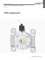
Fangvorrichtung TSN0
Montage-und Betriebsanleitung
08.2023
www.marantec.com

2 –Fangvorrichtung TSN0 / Rev.C 01
1. Inhaltsangabe
1. Inhaltsangabe 2
2. Angaben zum Dokument 2
3. Allgemeine Sicherheitshinweise 3
5. Produktbeschreibung 4
4. Produktübersicht 4
6. Montage 5
7. Fangfall 6
8. Prüfung 7
9. Wartung 7
10. Abmessungen 8
11. Technische Daten 8
12. Konformitätserklärung 9
Originalanleitung
−Urheberrechtlich geschützt.
−Nachdruck, auch auszugsweise, nur mit unserer
Genehmigung.
−Änderungen, die dem technischen Fortschritt dienen,
vorbehalten.
−Alle Maßangaben in Millimeter.
−Darstellungen sind nicht maßstabsgetreu.
Symbolerklärung
GEFAHR!
Sicherheitshinweis auf eine Gefahr, die unmittelbar zu Tod
oder zu schweren Verletzungen führt.
WARNUNG!
Sicherheitshinweis auf eine Gefahr, die zu Tod oder zu
schweren Verletzungen führen kann.
VORSICHT!
Sicherheitshinweis auf eine Gefahr, die zu leichten bis
mittelschweren Verletzungen führen kann.
ACHTUNG!
Sicherheitshinweis auf eine Gefahr, die zu Beschädigungen
oder zur Zerstörung des Produkts führen kann.
KONTROLLE
Hinweis auf eine durchzuführende Kontrolle.
VERWEIS
Verweis auf separate Dokumente die zu beachten sind.
HandlungsaufforderungHandlungsaufforderung
−Liste, Aufzählung
ÔVerweis auf andere Stellen in diesem Dokument
2. Angaben zum Dokument

Fangvorrichtung TSN0 / Rev.C 01– 3
DE
3. Allgemeine Sicherheitshinweise
GEFAHR!
Lebensgefahr durch Nichtbeachtung der
Dokumentation!
Beachten Sie alle Sicherheitshinweise in diesem
Beachten Sie alle Sicherheitshinweise in diesem
Dokument.
Dokument.
Gewährleistung
Eine Gewährleistung in Bezug auf Funktion und Sicherheit
erfolgt nur, wenn die Warn- und Sicherheitshinweise in dieser
Betriebsanleitung beachtet werden.
Für Personen- oder Sachschäden, die durch Nichtbeachtung
der Warn- und Sicherheitshinweise eintreten, haftet
die Marantec Legden GmbH & Co. KG nicht.
Für Schäden, die durch die Verwendung von nicht zugelas-
senen Ersatzteilen und Zubehör entstehen, ist jede Haftung
und Gewährleistung seitens Marantec Legden ausgeschlos-
sen.
Bestimmungsgemäße Verwendung
Die Fangvorrichtung TSN0 ist zur Sicherung gegen Absturz
von Rollläden bzw. Toren bestimmt. Der Hersteller haftet nicht
für Schäden, welche durch andere Anwendungen entstanden
sind. Nur bei bestimmungsgemäßer Anwendung ist eine
Betriebssicherheit gewährleistet.
Zielgruppe
Nur qualizierte und geschulte Fachmonteure dürfen die
Fangvorrichtung montieren und die mechanische Wartung
durchführen. Qualizierte und geschulte Fachmonteure erfül-
len folgende Anforderungen:
− Kenntnis der allgemeinen und speziellen Sicherheits- und
Unfallverhütungsvorschriften,
−Kenntnis der einschlägigen Vorschriften,
− Ausbildung in Gebrauch und Pege angemessener
Sicherheitsausrüstung,
− Fähigkeit, Gefahren in Zusammenhang mit der Montage zu
erkennen.
Nur qualizierte und geschulte Elektrofachkräfte dürfen die
Fangvorrichtung anschließen und die elektrische Wartung
durchführen. Qualizierte und geschulte Elektrofachkräfte
erfüllen folgende Anforderungen:
− Kenntnis der allgemeinen und speziellen Sicherheits- und
Unfallverhütungsvorschriften,
− Kenntnis der einschlägigen elektrotechnischen Vorschriften,
− Ausbildung in Gebrauch und Pege angemessener
Sicherheitsausrüstung,
− Fähigkeit, Gefahren in Zusammenhang mit Elektrizität zu
erkennen.
Hinweise zu Montage und Anschluss
−Vor Montagearbeiten muss die Anlage von der Stromver-
sorgung getrennt werden. Während der Arbeiten muss
sichergestellt werden, dass die Stromversorgung unterbro-
chen bleibt.
− Die örtlichen Schutzbestimmungen sind zu beachten.

4 –Fangvorrichtung TSN0 / Rev.C 01
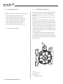
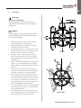
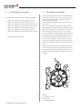
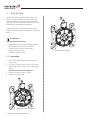
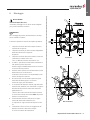
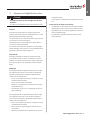
5. Produktbeschreibung
Die Fanvorrichtung TSN0 ist eine drehzahlabhängige externe
Fangvorrichtung, die als Sicherung für unbeabsichtigtes
Schließen von Verschlussvorrichtungen, wie beispielweise
Tore, dient.
Die Fangvorrichtung ist drehrichtungsunabhängig und war-
tungsfrei.
Durch Verschleiß kann das Tragmittel (Kette, Getriebe, Seile
etc.) des Tores eventuell versagen und das Tor würde unbe-
absichtigt schließen („abstürzen“). Die Drehzahl der Torwelle
erhöht sich in diesem Fall bis zur Auslösedrehzahl der Fang-
vorrichtung. Nach Überschreiten dieser Auslösedrehzahl wird
die Fangvorrichtung durch ein Sperrorgan ausgelöst und bis
zum Stillstand gebremst. Dies führt zur gedämpften Aufnah-
me der Energie des bewegten Tores und somit zum Anhalten
des Tores („Fangfall“).
In der Fangposition wird eine weitere Torbewegung über
eine elektrische Verrieglung durch den Schalter der Fangvor-
richtung verhindert. Nach einem Fangfall muss die Fangvor-
richtung durch geschultes Fachpersonal instand gesetzt oder
getauscht werden.
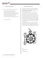
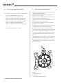
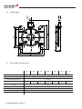
Legende:
A - Wellenaufnahme
B - Schalter
C - Montagebefestigung
4. Produktübersicht
Folgende Liefervarianten der Fangvorrichtung sind möglich:
−TSN0-A mit Wellenaufnahme Vierkant 13mm
−TSN0-B mit Wellenaufnahme Vierkant 16mm
−TSN0-C mit Wellenaufnahme Rund mit Nut 16mm
−TSN0-D mit Wellenaufnahme Rund mit Nut 18mm
−TSN0-E mit Wellenaufnahme Kleeblatt 16,8mm
−TSN0-F mit Wellenaufnahme Vierkant 18mm
−TSN0-G mit Wellenaufnahme Rund mit Nut 17mm
− Kundenspezische Montageplatte

Fangvorrichtung TSN0 / Rev.C 01– 5
DE
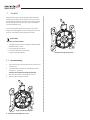
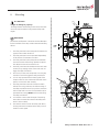
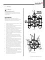
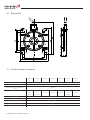
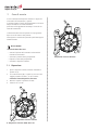
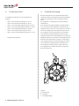
Erlaubt!
Nicht Erlaubt!
6. Montage
ACHTUNG!
Warnung vor Sachschäden!
Bauseitige Befestigungselemente, sowie die Befesti-
gungsschrauben, müssen für das mögliche Fangmoment
ausgelegt sein.
VERWEIS
Für die Montage des Tores, des Antriebes und der Befehls-
und Sicherheitsgeräte sind die Anleitungen der jeweiligen
Hersteller zu berücksichtigen.
1. Die Fangvorrichtung soll immer an der dem Antrieb
entgegen gesetzten Seite montiert werden.
2. Die Fangvorrichtung kann unabhängig von der Abroll-
richtung des Tores montiert werden.
3. Die Fangvorrichtung muss so montiert werden, dass die
Schalterauageäche immer nach oben zeigt. Die zuläs-
sige Abweichnung darf maximal ±6° betragen.
4. Die Wellen - Zapfen - müssen zentrisch mit dem Trä-
gerrohr verschweißt werden, weil durch eine Taumel-
bewegung der Trägerachse die Fangvorrichtung sofort
ansprechen kann.
5. Eventuell verwendete Antriebsketten sind straff gespannt
zu halten, um ein ruckartiges Anlaufen zu vermeiden,
welches ebenfalls zum Ansprechen der Fangvorrichtung
führen kann.
6. Saubere, seitliche Panzerführungen, sowie einen ge-
schmeidige Schlossbildung der einzelnen Panzerprofile
miteinander, sind ebenfalls von großer Wichtigkeit.
7. Das Aufschieben der Fangvorrichtung auf die Wellen
muss leichtgängig, unter Verwendung eines Schmiermit-
tels, erfolgen. Die Wellenaufnahme der Fangvorrichtung
muss formschlüssig auf der Welle sitzen und muss bei
runden Wellen gegen Verdrehen gesichert werden. Die
Fangvorrichtung -NIE- mit Gewalt montieren.
8. Es ist unbedingt darauf zu achten, dass das Drehmoment
des Antriebsmotors nicht größer ist als die Fangvorrich-
tungen aufnehmen können.
9. Der Verrieglungsschalter ist am Gehäuse der Fangvor-
richtung befestigt und muss an den Sicherheitskreis der
Steuerung des Antriebs angeschlossen werden.

6 –Fangvorrichtung TSN0 / Rev.C 01
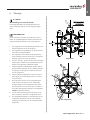
7. Fangfall
Beim Ansprechen der Fangvorrichtungen aufgrund einer Be-
triebsstörung verdrehen sich die Deckel relativ zum Gehäuse
und gleichzeitig unterbricht der elektrische Sicherheitsschalter,
der auf dem Gehäuse fest positioniert ist, den Sicherheitskr-
reis der Antriebssteuerung.
Die Funktionsfähigkeit der Abrollsicherung ist nach einem
Fangfall nicht mehr gegeben und muss durch geschultes Fach-
personal instand gesetzt oder ausgetauscht werden.
ACHTUNG!
Warnung vor Sachschäden!
−Toranlage stromlos schalten und gegen unbeabsichtigtes
Wiedereinschalten sichern
−Das Tor gegen Absturz sichern
−Ursache des Absturzes instand setzen
−Fangvorrichtung demontieren
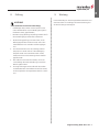
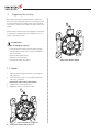
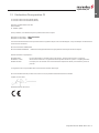
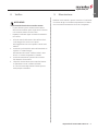
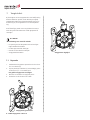
7.1 7.1 InstandsetzungInstandsetzung
1. Demontierte Fangvorrichtung öffnen durch Lösen der vier
Schrauben (A).
2. Sind Sperrrad (B) und Deckel (C) unbeschädigt, weiter
mit Schritt 3 - Ansonsten:
Tauschen der kompletten Fangvorrichtung!
3. Montieren der Deckel in ausgerichteter Position.
4. Anziehen der Schrauben mit 14Nm.
Fangvorrichtung ausgelöst
Fangvorrichtung ausgerichtet

Fangvorrichtung TSN0 / Rev.C 01– 7
DE
ACHTUNG!
Sachschaden durch unterlassende Prüfung!
−Kraftbetätigte Türen, Fenster und Tore müssen vor der
ersten Inbetriebnahme und nach Bedarf, jedoch jährlich
mindestens einmal, geprüft werden.
−Beachten Sie bzgl. Wartung und Prüfung weiterhin die für
den Einsatzfall gültigen Vorschriften und Normen.
1. Bei der Sichtungsprüfung ist zu kontrollieren, ob die
Befestigungsschrauben auf den Konsolen und an den
Gehäusedeckeln noch vorhanden und fest angezogen
sind.
2. Der Sicherheitschalter muss auf eindeutige Schaltno-
ckenposition im Deckel und auf sichere Befestigung
überprüft werden. Der Zustand des Kabels und der
korrekte Anschluss an die Steuerung müssen ebenfalls
geprüft werden.
3. Rein äußerlich muss kontrolliert werden, ob sich Kor-
rosionsbildung oder starke Veränderung im statischen
Bereich ergeben haben.
4. Die Fangvorrichtungen müssen während des Vorwärts-
und Rückwärtslaufes durch Abhören kontrolliert werden,
ob die Fallgeräusche der Fangelemente deutlich zu hören
sind.
8. Prüfung
Durch Verwendung von korrosionsgeschützten Materialien und
durch den Einbau von nadellagern mit Dauerschmierung sind
die Abrollsicherungen wartungsfrei.
9. Wartung

8 –Fangvorrichtung TSN0 / Rev.C 01
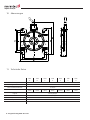
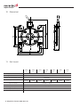
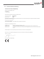
10. Abmessungen
TSN0
-A-
TSN0
-B-
TSN0
-C-
TSN0
-D-
TSN0
-E-
TSN0
-F-
TSN0
-G-
Maximales Fangmoment 591 Nm
Zulässiges Drehmoment 145 Nm
Maximale Betriebsdrehzahl 22 U/min
Wellenaufnahme Vierkant
13mm
Vierkant
16mm
Rund
16mm
Rund
18mm
Kleeblatt
16,8mm
Vierkant
18mm
Rund
17mm
Lagerart Flanschgelagert
Gewicht 0,830 kg
Temperaturbereich -20°C ... +60°C
Schutzart Schalter IP 65
Prüfnummer 24 42140-2
11. Technische Daten

Fangvorrichtung TSN0 / Rev.C 01– 9
DE
im Sinne der Richtlinie 2014/30/EU (EMV)
im Sinne der Richtlinie 2011/65/EU (RoHS)
Marantec Legden GmbH & Co.KG,
Neue Mühle 4,
D - 48739 Legden
Hiermit erklären wir, dass das nachfolgend aufgeführte Produkt
Produktbezeichnung: Fangvorrichtung
Typenbezeichnung: TSNO
ausschließlich für den Einbau in einer Toranlage bestimmt ist und in Übereinstimmung mit folgenden Richtlinien
entwickelt, konstruiert und gefertigt wurde:
Maschinen-Richtlinie 2006/42/EG
RoHS Richtlinie 2011/65/EU - Gefahrstoffe in Elektrogeräten
Angewandte und herangezogene Normen:
EN 12604:2021 Tore - Mechanische Aspekte: Anforderungen und Prüfverfahren
EN 60204-1:2019 Sicherheit von Maschinen - Elektrische Ausrüstung von Maschinen - Teil 1: Allgemeine
Anforderungen
GS-BE-04:2001 Grundsätze für die Prüfung und Zertizierung von Fangvorrichtungen für Fenster, Türen und
Tore
Bevollmächtigter für die Zusammenstellung der technischen Unterlagen ist der Unterzeichner.
Bei einer nicht mit uns abgestimmten Änderung des Produktes verliert diese Erklärung ihre Gültigkeit.
Legden, den 01.11.2022
Michael Hörmann, Geschäftsleitung
12. Konformitätserklärung

10 –Fangvorrichtung TSN0 / Rev.C 01

Safety catch device TSN0 / Rev.C 01– 1
EN
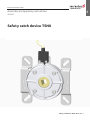
Safety catch device TSN0
Assembly and operating instructions
08.2023
www.marantec.com

2 – Safety catch device TSN0 / Rev.C 01
1. Contents
1. Contents 2
2. Information in this document 2
3. General safety instructions 3
5. Product description 4
4. Overview of product 4
6. Mounting 5
7. Triggering due to drop 6
8. Inspection 7
9. Maintenance 7
10. Dimensions 8
11. Technical data 8
12. Declaration of conformity 9
13. Declaration of conformity(UK) 10
Original operating instructions
−Protected by copyright.
−No part of these instructions may be reproduced without
our prior approval.
−Subject to alterations in the interest of technical progress.
−All dimensions are given in millimetres.
−The illustrations are not true to scale.
Key to symbols
DANGER!
Safety notice indicating a danger that will directly result in
death or severe injury.
WARNING!
Safety notice indicating a danger that could result in death
or severe injury.
CAUTION!
Safety notice indicating a danger that can result in slight or
moderate injuries.
ATTENTION!
Safety notice indicating a danger that can result in damage
to property or in irreparable damage to the product.
CHECK
Reference to a check that needs to be carried out.
REFERENCE
Reference to separate documents that must be observed.
Instruction requiring actionInstruction requiring action
−List, itemisation
ÔReference to other sections of this document
2. Information in this document

Safety catch device TSN0 / Rev.C 01– 3
EN
3. General safety instructions
DANGER!
Failure to comply with the documentation could
result in life-threatening danger!
Be sure to follow all the safety instructions in this docu-
Be sure to follow all the safety instructions in this docu-
ment.
ment.
Warranty
The function and safety of the equipment is only guaranteed
if the warning and safety instructions included in these oper-
ating instructions are adhered to.
Marantec Legden GmbH + Co. KG is not liable for personal
injury or damage to property if these occur as a result of the
warnings and safety advice being disregarded.
Marantec Legden does not accept any liability or warranty
for damage due to the use of non-approved spare parts and
accessories.
Use for the intended purpose
The safety catch device TSN0 is intended to prevent roller
shutters or doors from falling. The manufacturer is not liable
for any damage due to use for other purposes. The operation-
al safety is only guaranteed if the safety catch device is used
for its intended purpose.
Target group
Only qualied and trained professionals are permitted to in-
stall and service the safety catch device. Qualied and trained
professionals must full the following requirements:
− have knowledge of the general and specic safety and ac-
cident prevention regulations,
−have knowledge of the relevant regulations,
− be trained in the use and care of appropriate safety equip-
ment,
− be capable of recognising the dangers associated with
installation.
Only qualied and trained electricians may connect and elec-
trically service the safety catch device. Qualied and trained
electricians must meet the following requirements:
− have knowledge of the general and specic safety and ac-
cident prevention regulations,
− have knowledge of the relevant electrical regulations,
− be trained in the use and care of appropriate safety equip-
ment,
− be capable of recognising the dangers associated with
electricity.
Instructions regarding installation and connection
−The system must be disconnected from the electricity supply
before carrying out installation. It must be ensured that the
electricity supply remains disconnected for the duration of
the work.
− Local protective regulations must be complied with.

4 – Safety catch device TSN0 / Rev.C 01
5. Product description
The safety catch device TSN0 is a rotation speed dependent
external safety catch device to prevent the unintentional clos-
ing of locking devices such as doors.
The safety catch device is independent of the direction of
rotation and maintenance-free.
As a result of wear, it is possible that the load bearing ele-
ments (chain, drive unit, ropes, etc.) of the door could fail
and that the door could close unintentionally ("drop"). In this
case the rotational speed of the shaft would increase until the
trip speed of the safety catch device is reached. After this trip
speed has been exceeded, the safety catch device is triggered
by a shutoff device and is braked until it comes to a standstill.
This results in the energy of the moving door being dampened
and absorbed and so the door is brought to a stop ("trigger-
ing due to drop").
In the arrested position, the door is electrically locked and
prevented from moving by the safety catch switch. After the
safety catch device has been triggered, the safety catch device
must either be repaired by a trained professional or replaced.
Key:
A - shaft mounting
B - switch
C - mounting xtures
4. Overview of product
The following safety catch devices models are available:
−TSN0-A with square shaft mounting 13mm
−TSN0-B with square shaft mounting 16mm
−TSN0-C with round shaft mounting with groove 16mm
−TSN0-D with round shaft mounting with groove 18mm
−TSN0-E with cloverleaf shaft mounting 16.8mm
−TSN0-F with square shaft mounting 18mm
−TSN0-G with round shaft mounting with groove 17mm
− Customised xing plate

Safety catch device TSN0 / Rev.C 01– 5
EN
Not permitted!
6. Mounting
ATTENTION!
Danger of damage to property!
The xing elements and the xing screws used at the instal-
lation site must be suitable for the potential safety catch
torque!
REFERENCE
The relevant manufacturers’ instructions must be adhered to
for the installation of the door, and the command and safety
devices.
1. The safety catch device must always be mounted on the
opposite side to where the drive is.
2. The safety catch device can be mounted independently
of the direction of movement of the door.
3. The safety catch device must always be mounted with
the switch contact surface facing upwards. The permis-
sible deviation must not be more than± 6°.
4. The shaft journals must be welded with the carrier tube
centred, as any swaying motion of the carrier axle will
trigger the safety catch device.
5. Drive chains, if used, must be kept taut to avoid a jerky
start which could also trigger the safety catch device.
6. It is also very important that the lateral guides of the
shutter curtain are clean and that the individual curtain
profiles lock into each other smoothly.
7. The safety catch device must be slid onto the shafts
without force using a lubricant. The shaft mounting of
the safety catch device must form a positive connection
with the shaft and in the case of round shafts must be
prevented from turning. NEVER use force when fitting
the safety catch device!
8. It is essential to ensure that the torque of the driving
motor does not exceed the value that the safety catch
device is able to absorb.
9. The interlock switch is fixed to the safety catch device
housing and must be connected to the safety circuit of
the drive control system.
Permitted!

6 – Safety catch device TSN0 / Rev.C 01
7. Triggering due to drop
If the safety catch device is triggered due to a malfunction,
the covers become displaced in relation to the housing and at
the same time the electrical safety switch, which is fastened
to the housing, interrupts the safety circuit of the drive control
system.
After the safety catch device has been triggered, it must either
be repaired by a trained professional or replaced, as it is no
longer in good working order.
ATTENTION!
Danger of damage to property!
−Disconnect the door system from the electricity supply
and take steps to ensure that it cannot be switched on
again by accident
−Secure the door against falling.
−Repair the cause of the drop
−Dismantle the safety catch device!
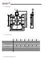
7.1 7.1 Repair:Repair:
1. Open dismantled safety catch device by loosening the
four screws (A).
2. If lock wheel (B) or cover (C) are undamaged proceed
with step 3 - otherwise:
Replace the entire safety catch device!
3. Fit the covers in the aligned position.
4. Tighten the screws to a torque of 14Nm.
Safety catch device triggered
Safety catch device aligned

Safety catch device TSN0 / Rev.C 01– 7
EN
ATTENTION!
Damage to property due to failure to test!
−Motorised windows, doors and gates must be tested
before start-up and as required, but at least once a year.
−For maintenance and testing, the relevant regulations
and directives for the use concerned must always be
observed
1. In the visual inspection, it must be checked whether the
xing screws on the brackets and the housing covers are
still there and are securely tightened.
2. The safety switch must be in a clear control cam position
in the cover and be securely xed. The state of the cable
and the correct connection to the controls must also be
checked.
3. It must be checked outwardly whether there is any corro-
sion or any marked static changes have occurred.
4. During forward and reverse operation, the safety catch
devices must be checked to monitor whether the drop-
ping noise of the catch elements can be clearly heard.
8. Inspection
Due to the use of corrosion-protected materials and needle
bearings with permanent lubrication, the anti drop devices are
maintenance-free.
9. Maintenance

8 – Safety catch device TSN0 / Rev.C 01
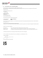
10. Dimensions
TSN0
-A-
TSN0
-B-
TSN0
-C-
TSN0
-D-
TSN0
-E-
TSN0
-F-
TSN0
-G-
Max. safety catch torque 591 Nm
Permissible torque 145 Nm
Max. operating speed 22 rpm
Shaft mounting square
13mm
square
16mm
round
16mm
round
18mm
cloverleaf
16.8mm
square
18mm
round
17mm
Type of bearing ange bearing
Weight 0.830 kg
Temperature range -20°C ... +60°C
Switch protection grade IP 65
Test number 24 42140-2
11. Technical data

Safety catch device TSN0 / Rev.C 01– 9
EN
in accordance with Directive 2014/30/EU (EMC)
in accordance with Directive 2011/65/EU (RoHS)
Marantec Legden GmbH & Co.KG,
Neue Mühle 4,
D - 48739 Legden
We hereby declare that the following listed product
Product designation: Safety catch device
Type designation: TSNO
is exclusively intended for integration in a door system and has been developed, designed and produced in accordance with
the following Directives:
Machinery Directive 2006/42/EC
RoHS Directive 2011/65/EU - Hazardous substances in electrical appliances
Applied and consulted standards:
EN 12604:2021 Doors - Mechanical aspects: Requirements and test methods
EN 60204-1:2019 Safety of machinery - Electrical equipment of machines - Part 1: General requirements
GS-BE-04:2001 Principlesforthetestingandcerticationofsafetycatchdevicesforwindows,doorsandgates
Authorised representative for compiling the technical documents is the undersigned.
Incaseofchangestotheproductthatarenotconrmedbyus,thisdeclarationisvoid.
Legden, 01.11.2022
Michael Hörmann, General Manager
12. Declaration of conformity

10 – Safety catch device TSN0 / Rev.C 01
within the context of Supply of Machinery (Safety) Regulations 2008
within the context of The Restriction of the Use of Certain Hazardous Substances in Electrical and Electronic Equipment
Regulations 2012
Marantec Legden GmbH & Co.KG,
Neue Mühle 4,
D - 48739 Legden
UK Representative:
Link Controls
Stuart Road, Manor Park
Runcorn Cheshire, WA7 1TS
We hereby declare that the following listed product
Product designation: Safety catch device
Type designation: TSNO
is exclusively intended for integration in a door system and has been developed, designed and produced in accordance with the
following Directives:
Supply of Machinery (Safety) Regulations (2008 No.1597)
The Restriction of the Use of Certain Hazardous Substances in Electrical and Electronic Equipment Regulations (2012 No.3032)
Applied and consulted standards:
EN 12604:2021 Doors - Mechanical aspects: Requirements and test methods
EN 60204-1:2019 Safety of machinery - Electrical equipment of machines - Part 1: General requirements
GS-BE-04:2001 Principlesforthetestingandcerticationofsafetycatchdevicesforwindows,doorsandgates
Authorised representative for compiling the technical documents is the undersigned.
Incaseofchangestotheproductthatarenotconrmedbyus,thisdeclarationisvoid.
Legden, 01.11.2022
Michael Hörmann, General Manager
13. Declaration of conformity(UK)
La page est en cours de chargement...
La page est en cours de chargement...
La page est en cours de chargement...
La page est en cours de chargement...
La page est en cours de chargement...
La page est en cours de chargement...
La page est en cours de chargement...
La page est en cours de chargement...
La page est en cours de chargement...
La page est en cours de chargement...
La page est en cours de chargement...
La page est en cours de chargement...
La page est en cours de chargement...
La page est en cours de chargement...
La page est en cours de chargement...
La page est en cours de chargement...
La page est en cours de chargement...
La page est en cours de chargement...
La page est en cours de chargement...
La page est en cours de chargement...
La page est en cours de chargement...
La page est en cours de chargement...
La page est en cours de chargement...
La page est en cours de chargement...
La page est en cours de chargement...
La page est en cours de chargement...
La page est en cours de chargement...
La page est en cours de chargement...
La page est en cours de chargement...
La page est en cours de chargement...
La page est en cours de chargement...
La page est en cours de chargement...
-
 1
1
-
 2
2
-
 3
3
-
 4
4
-
 5
5
-
 6
6
-
 7
7
-
 8
8
-
 9
9
-
 10
10
-
 11
11
-
 12
12
-
 13
13
-
 14
14
-
 15
15
-
 16
16
-
 17
17
-
 18
18
-
 19
19
-
 20
20
-
 21
21
-
 22
22
-
 23
23
-
 24
24
-
 25
25
-
 26
26
-
 27
27
-
 28
28
-
 29
29
-
 30
30
-
 31
31
-
 32
32
-
 33
33
-
 34
34
-
 35
35
-
 36
36
-
 37
37
-
 38
38
-
 39
39
-
 40
40
-
 41
41
-
 42
42
-
 43
43
-
 44
44
-
 45
45
-
 46
46
-
 47
47
-
 48
48
-
 49
49
-
 50
50
-
 51
51
-
 52
52


dans d''autres langues
- italiano: Marantec TSN0 Manuale del proprietario
- English: Marantec TSN0 Owner's manual
- Deutsch: Marantec TSN0 Bedienungsanleitung
- Nederlands: Marantec TSN0 de handleiding
