La Crosse Technology WS-7394U Manuel utilisateur
- Catégorie
- Stations météo
- Taper
- Manuel utilisateur

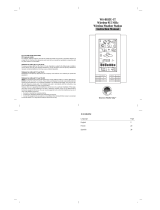
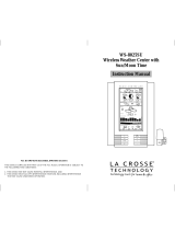
WS-7394U
Wireless 433 MHz
Weather Station
Instruction Manual
R
FCC DISCLAIMER
FCC ID: OMO-01RX (Receiver), OMO-01TX (transmitter)
This device complies with part 15 of the FCC rules. Operation is sub-
ject to the following two conditions:
(1)This device may not cause harmful interference.
(2)This device must accept any interference received, including inter
ference that may cause undesired operation.

Contents
Language Page
English 2
French 18
Spanish 36
TABLE OF CONTENTS
Topic Page
Inventory of Contents/ Additional Equipment 3
About WWVB 3
Quick Set Up Guide 4
Detailed Set Up Guide
Battery Installation 5
Start Up Sequence 6
Explanation of LCD Information 7
Function Key Layout 8
Program Mode
Overview of Programming Sequence 8
LCD Contrast Setting 8
Time Zone Setting 9
DST ON/OFF Setting 9
Radio-controlled Time ON/OFF Setting 10
12/24-hour Time Mode Setting 10
Setting the Time/Date Manually 11
Temperature Measuring Units (˚F/˚C) 12
Air Pressure Measuring Units (inHg/hPa) 13
Relative Pressure Setting 13
Forecast Sensitivity Setting 14
Features and Operation
Minimum/Maximum Temperature/Humidity 14
Multiple Remote Temperature/Humidity Sensors 15
Comfort Icon 16
Weather Forecast and Pressure Trend Indicators 16
Weather Icons 17
Weather Tendency Arrows 17
Barometric Air Pressure Reading 18
Air Pressure History Bar Chart 18
Mounting 19
Maintenance and Care 20
Troubleshooting Guide 20
Specifications 21
Warranty Information 22
GB
P.2

INVENTORY OF CONTENTS
1. WS-7394U-indoor weather station
2. TX6U-remote temperature (temperature/humidity) sensor
3. Instruction manual and warranty card
ADDITIONAL EQUIPMENT (not included)
1. Five fresh AA 1.5V alkaline batteries.
2. One wall-mounting screw (optional)
ABOUT WWVB (radio-controlled time)
The NIST (National Institute of Standards and Technology-Time and
Frequency Division) radio station, WWVB, is located in Ft. Collins,
Colorado and transmits the exact time signal continuously throughout
the United States at 60 kHz. The signal can be received up to 2,000
miles away through the internal antenna in the indoor weather station.
However, due to the nature of the Earth’s Ionosphere, reception is
very limited during daylight hours. The indoor weather station will search
for a signal every night when reception is best. The WWVB radio sta-
tion derives its signal from the NIST Atomic clock in Boulder, Colorado.
A team of atomic physicists continually measure every second of ev-
ery day to an accuracy of ten billionths of a second a day. These
physicists have created an international standard, measuring a sec-
ond as 9,192,631,770 vibrations of a Cesium 133 atom in a vacuum.
For more information about WWVB please see the NIST website at
http://www.boulder.nist.gov/timefreq/stations/wwvb.htm
QUICK SET-UP GUIDE
Hint:
Use good quality Alkaline Batteries and avoid rechargeable
batteries.
1. Have the indoor weather station and remote temperature sensor 3
to 5 apart.
2. Batteries should be out of both units for 15 minutes.
3. Place the batteries into the remote temperature sensor first then
into the indoor weather station.
(All remote temperature sensors must be started before the indoor
weather station)
4. DO NOT PRESS ANY BUTTONS FOR 15 MINUTES.
In this time the indoor weather station and remote temperature sensor
will start to talk to each other and the indoor weather station will show
both the indoor temperature and humidity and the outdoor temperature.
If the indoor weather station does not display all values after the 15
minutes please retry the set up as stated above. After all values are
displayed for 15 minutes you can place your remote temperature sen-
sor outdoors and set your time.
The remote temperature sensor should be placed in a dry, shaded
area. The remote temperature sensor has a range of 330 feet. Any
walls that the signal will have to pass through will reduce distance. An
outdoor wall or window will have 20 to 30 feet of resistance and an
interior wall will have 10 to 20 feet of resistance. Your distance plus
resistance should not exceed 330 ft. in a straight line.
NOTE:
Fog and mist will not harm your remote temperature sensor
but direct rain must be avoided.
To complete the set up of your indoor weather station after the 15
minutes have passed please follow the steps in the Detailed Set Up
Guide.
Note:
The remote temperature sensor transmits a signal every 3
minutes; after the batteries have been installed, the indoor weather
station will search for the signal for a duration of 5 minutes. If there is
no temperature reading in the OUTDOOR LCD after 5 minutes, make
sure the units are within range of each other, or repeat the battery
installation procedure.
GB
P.3
GB
P.4

DETAILED SET-UP GUIDE
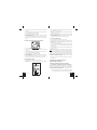
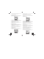
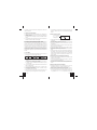
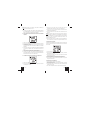
I. Battery Installation
Batteries will fit tightly. To avoid start-up problems, make sure that the
batteries do not spring free. Also be sure to insert alkaline batteries
into the remote temperature sensor first, then the indoor weather station.
Initial set up should be done with the remote temperature sensor and
indoor weather station in the same room. The units should be perma-
nently mounted only after the signal reception has been verified.
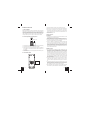
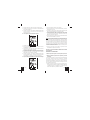
A. Remote Temperature and Humidity Sensor
1. Remove the mounting bracket. The bracket snaps on and off easily.
2. Remove the battery cover, by sliding the cover down.
3. Observing the correct polarity install 2 AA batteries. The batteries
will fit tightly (to avoid start-up problems make sure they do not
spring free).
4. Replace the battery cover by sliding upwards. Be sure battery cover
is on securely.
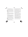
B. Indoor Weather Station
1. Remove the battery cover (the cover has white writing on it).
2. Observe the correct polarity, and install two Alkaline AA batteries.
3. Do not press any buttons for at least ten minutes. If a button is
pressed before the indoor weather station has received informa-
tion from the TX6U sensor, no data will be received from that sen-
sor until reset.
4. Replace the battery cover.
II. Start Up Sequence
A. Initial Start
1. Immediately after the batteries have been installed the LCD will
completely light up for a brief moment.
2. All information will then appear in normal mode, with “12:00” as the
default time and “WE.1” as the default date (2004 as the year).
3. The indoor temperature and humidity, and barometric air pressure
(as 29.91 inHg relative RH) will also be displayed.
4. There is a “satellite” icon that appears in the bottom portion of the
LCD, to the left of the outdoor temperature- this icon informs the
user that the indoor weather station is looking for signals from the
remote temperature sensor. Within five minutes the remote tem-
perature should be displayed-if not, remove batteries from all units
and repeat battery installation, the remote temperature sensor first,
then the indoor weather station.
B. WWVB Reception
1. Once the batteries are installed in the indoor weather station it will
automatically search for the WWVB signal. If it receives a good
signal (which is unlikely during daylight hours in most locations),
the WWVB reception indicator (looks like a tower icon) will flash.
The indoor weather station requires five full minutes of good recep-
tion to successfully capture the signal and set to the correct hour,
minute, second, month, day and year. If the signal reception is not
successful within ten minutes, the signal search will be cancelled
and will automatically resume every two hours until the signal is
successfully captured.
2. The signal is sent from Ft. Collins, Colorado only and is similar to
an AM radio signal. Atmospheric interferences such as storms,
sunspots, and even sunlight will cause the signal to not travel as
far.
3. To maximize reception, place the indoor weather station in a win-
dow facing Colorado, at least six feet from any electrical source
(computers, televisions, refrigerators, etc.). Do not move the in-
door weather station while it is searching for the signal.
4. The time and date can be manually set. Once the signal is captured,
it will override any time and date set to the time zone selected.
Battery Cover
GB
P.5
GB
P.6

5. Once the time and date are set, the indoor weather station will
conduct a search every night at midnight and correct to the accu-
rate time and date (Daylight Saving Time is automatic). If the signal
has been received in the past 24 hours, the reception indicator will
be displayed.
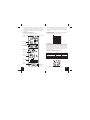
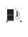
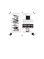
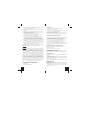
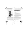
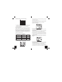
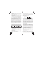
III. Explanation of LCD Information
A. The below picture highlights the LCD features.
B. There are many different modes the indoor weather station can be
set to. The LCD shown is the normal operating mode, and your
actual data shown will be different based on your local settings and
conditions.
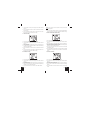
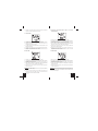
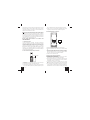
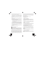
IV.Function Key Layout
A. The below picture shows the four function keys used in program-
ming and operation of your indoor weather station
V. Program Mode
The program mode is laid out in a manner that allows you to program
each function separately, or you can follow the instructions entirely to
program the indoor weather center. Complete programming is usually
done for the initial set-up, and will require you to skip step 1,2 and 3 of
each programming section. The programming mode can be exited at
any time by either pressing the “CH” button, or waiting for the 15-sec-
ond time-out to take effect.
A. Overview of programming mode sequence
1. LCD Contrast 2. Time Zone 3. DST ON/OFF
4. Radio-controlled 5. 12/24-hour 6. Hour
Time ON/OFF time mode
7. Minute 8. Year 9. Month
10. Date 11. ˚F/˚C 12.inHg/hPa
13. Relative pressure setting 14. Forecast sensitivity
B. LCD Contrast Setting
1. Press and hold the “SET” button for five seconds.
Radio-controlled
time
WWVB Reception
Indicator
Date Display
Comfort Icon
Indoor Temperature
Humidity Display
Air Pressure Trend
Indicator
Forecast Icon
Barometric Air
Pressure
12-hour Air
Pressure History
Outdoor
Temperature Display
Remote Sensor
Number (Up to 3
To ta l)
GB
P.7
GB
P.8

2. “lcd” will appear at the top of the display and a number will flash
next to it.
3. Press and release the “OUT/+” button to select the desired LCD
contrast setting.
4. Press and release the “SET” button to confirm the LCD contrast
setting and continue to the Time Zone setting.
C. Time Zone Setting
1. Press and hold the “SET” button for five seconds.
2. “lcd” will appear at the top of the display and a number will flash
next to it.
3. Press and release the “SET” button once more to advance to the
Time Zone setting.
4. A number will flash to the left of the letter “h” at the top of the display
just below the time display.
5. Press and release the “OUT+” button to select the desired time
zone.
6. Press and release the “SET” button to confirm the Time Zone set-
ting and continue to the DST ON/OFF setting.
D. DST ON/OFF Setting
1. Press and hold the “SET” button for five seconds.
2. “lcd” will appear at the top of the display and a number will flash
next to it.
3. Press and release the “SET” button twice more to advance to the
DST ON/OFF setting.
4. “DST” will appear above the indoor temperature/humidity display
and “ON” or “OFF” will flash above that.
5. Press and release the “OUT/+” button to select DST ON/OFF.
Note:
Some locations (Arizona and parts of Indiana) do not follow
Daylight Saving Time.
6. Press and release the “SET” button to confirm the DST ON/OFF
setting and continue to the Radio-controlled Time ON/OFF setting.
E. Radio-controlled Time ON/OFF Setting
1. Press and hold the “SET” button for five seconds.
2. “lcd” will appear at the top of the display and a number will flash
next to it.
3. Press and release the “SET” button three more times to advance to
the Radio-controlled time ON/OFF setting.
4. “RCC” will appear above the indoor temperature/humidity display
and “ON” or “OFF” will flash above that.
5. Press and release the “OUT/+” button to select Radio-controlled
time ON/OFF setting.
6. Press and release the “SET” button to confirm the Radio-controlled
time ON/OFF setting and continue to the 12/24-hour Time Mode
setting.
F. 12/24-hour Time Mode
1. Press and hold the “SET” button for five seconds.
2. “lcd” will appear at the top of the display and a number will flash
next to it.
3. Press and release the “SET” button four more times to advance to
the 12/24-hour time mode setting.
4. “12h” or “24h” will flash above the indoor temperature/humidity
display.
5. Press and release the “OUT/+” button to select 12 or 24-hour time
mode.
GB
P.9
GB
P.10

Note:
In 12h mode “PM” will appear to the left of the time during PM
hours. If the time is not within the PM hours nothing will be displayed.
Be sure to set the time to the correct AM/PM time to ensure automatic
reception.
6. Press and release the “SET” button to confirm the 12/24-hour time
mode setting and continue to the Hour setting
G. Setting The Hour Manually
The WWVB signal will override any manual set time and date
information. The time will be based on the time zone selected.
1. Press and hold the “SET” button for five seconds.
2. “lcd” will appear at the top of the display and a number will flash
next to it.
3. Press and release the “SET” button five more times to advance to
the Manual Hour setting.
4. The hour will begin to flash at the top of the display.
5. Press and release the “OUT/+” button to select the desired hour.
6. Press and release the “SET” button to confirm the hour setting and
continue to the Minute setting.
H. Setting The Minutes Manually
1. Press and hold the “SET” button for five seconds.
2. “lcd” will appear at the top of the display and a number will flash
next to it.
3. Press and release the “SET” button six more times to advance to
the Manual Minutes setting.
4. The minutes will begin to flash at the top of the display.
5. Press and release the “OUT/+” button to select the desired minutes.
6. Press and release the “SET” button to confirm the minutes and
continue to the Year setting.
I. Setting The Year Manually
1. Press and hold the “SET” button for five seconds.
2. “lcd” will appear at the top of the display and a number will flash
next to it.
3. Press and release the “SET” button seven more times to advance
to the Manual Year setting.
4. The year will begin to flash below the time display.
5. Press and release the “OUT/+” button to select the desired year.
6. Press and release the “SET” button to confirm the year and con-
tinue to the Month setting.
J. Setting The Month Manually
1. Press and hold the “SET” button for five seconds.
2. “lcd” will appear at the top of the display and a number will flash
next to it.
3. Press and release the “SET” button eight more times to advance to
the Manual Month setting.
4. The Month will begin to flash below the time display.
5. Press and release the “OUT/+” button to select the desired month.
6. Press and release the “SET” button to confirm the month and con-
tinue to the Date setting.
K. Setting The Date Manually
1. Press and hold the “SET” button for five seconds.
2. “lcd” will appear at the top of the display and a number will flash
next to it.
3. Press and release the “SET” button nine more times to advance to
the Manual Date setting.
4. The date will begin to flash below the time display.
5. Press and release the “OUT/+” button to select the desired date.
6. Press and release the “SET” button to confirm the date and con-
tinue to the Temperature Measuring Units setting.
L. Temperature Measuring Units Selection (˚F or ˚C)
1. Press and hold the “SET” button for five seconds.
GB
P.11
GB
P.12

2. “lcd” will appear at the top of the display and a number will flash
next to it.
3. Press and release the “SET” button ten more times to advance to
the Temperature Measuring Units setting.
4. ˚F or ˚C will flash at the top of the display.
5. Press and release the “OUT/+” button to select the desired tem-
perature-measuring unit.
6. Press and release the “SET” button to confirm the temperature-
measuring unit and continue to the Air Pressure Measuring Units
setting.
M. Air Pressure Measuring Units Selection (inHg/hPa)
1. Press and hold the “SET” button for five seconds.
2. “lcd” will appear at the top of the display and a number will flash
next to it.
3. Press and release the “SET” button eleven more times to advance
to the Air Pressure Measuring Units setting.
4. inHg or hPa will flash at the top of the display.
5. Press and release the “OUT/+” button to select the desired air pres-
sure-measuring unit.
6. Press and release the “SET” button to confirm the air pressure-
measuring unit and continue to the Relative Pressure setting.
N. Relative Pressure Setting
1. Press and hold the “SET” button for five seconds.
2. “lcd” will appear at the top of the display and a number will flash
next to it.
3. Press and release the “SET” button twelve more times to advance
to the Relative Pressure setting.
4. The barometric air pressure will flash in the middle of the display,
just below the forecast icon
5. Press and release the “OUT/+” or “IN” button to select the desired
air pressure-measuring unit.
6. Press and release the “SET” button to confirm the relative pressure
setting and continue to the Forecast Sensitivity setting.
O. Forecast Sensitivity Setting
1. Press and hold the “SET” button for five seconds.
2. “lcd” will appear at the top of the display and a number will flash
next to it.
3. Press and release the “SET” button thirteen more times to advance
to the Forecast sensitivity setting.
4. The two air pressure tendency arrows will begin flashing on either
side of the forecast icon and a flashing number will appear under
the forecast icon.
5. Press and release the “OUT/+” button to select the desired forecast
sensitivity setting.
Note:
Barometric air pressure is usually reported as “relative air
pressure”. This reading is based on the combination of absolute air
pressure and altitude. In general, an increase in altitude will result in a
decrease in air pressure. Relative air pressure will make readings in
nearby locations relative to each other to allow for proper forecasting.
The absolute air pressure reading in the Weather Center cannot be
calibrated, only the relative air pressure.
6. Press and release the “SET” button to confirm the forecast sensi-
tivity setting.
THE MANUAL SETTING IS NOW COMPLETED
FEATURES AND OPERATIONS
A. Minimum and Maximum Temperature and Humidity
1. Indoor Minimum and Maximum Temperature and Humidity
The indoor weather station automatically stores the minimum and
maximum indoor temperature and humidity. The minimum and maxi-
mum values are updated automatically when a new minimum or maxi-
mum is recorded, or until manually reset.
a. From the normal display mode, press and release the “IN” key
once to view the indoor maximum temperature and humidity
GB
P.13
GB
P.14

(“MAX” will be displayed above the indoor temperature and
humidity).
b. Press and release the “IN” key again to view the indoor mini-
mum temperature and humidity.
c. Press and release the “IN” key again to return to the normal
mode (timeout of viewing minimum/maximum values will occur
if no keys are pressed for fifteen seconds).
Note:
To reset the indoor minimum and maximum temperature and
humidity, first display the values you wish to reset (minimum or
maximum). Next press and hold the “SET” key for at least three
seconds. You will see then that the values will reset to the current
temperature and humidity and corresponding time.
2. Outdoor Minimum and Maximum Temperature
The indoor weather station automatically stores the minimum and
maximum outdoor temperature. The minimum and maximum values
are updated automatically when a new minimum or maximum is
recorded, or until manually reset.
a. From the normal display mode, press and release the “OUT/+”
key once to view the outdoor maximum temperature (“MAX” will
be displayed above the outdoor temperature).
b. Press and release the “OUT/+” key again to view the outdoor
minimum temperature.
c. Press and release the “OUT/+” key again to return to the normal
mode (timeout of viewing minimum/maximum values will occur
if no keys are pressed for fifteen seconds).
Note:
To reset the outdoor minimum and maximum temperature, first
display the values you wish to reset (minimum or maximum). Next
press and hold the “SET” key for at least three seconds. You will see
then that the values will reset to the current temperature and corre-
sponding time.
B. Multiple Remote Temperature Sensors
The WS-7394U is able to receive signals from 3 different remote
sensors. These extra remote sensors can be purchased through the
same dealer as this unit. A TX4U will monitor the temperature and
humidity, a TX3U will monitor temperature and display the tempera-
ture on its LCD, a TX3UP will monitor the temperature via a probe for
measuring soil or water temperatures and a TX6U will monitor the
temperature only.
Note:
When setting up multiple units it is important to insert batteries
first into all the remote sensors, and in numeric sequence. Second
install batteries into the indoor weather station. Transmission prob-
lems will arise if this is not done correctly and if the total time for set-up
exceeds 6 minutes
1. Set Up of Multiple Units
a. It is necessary to remove the batteries from all units currently in
operation.
b. Remove the battery covers to all remote sensors.
c. Place all remote sensors in a numeric sequential order.
d. In sequential order, install batteries following the same battery in-
stallation procedures seen in Detailed Set-Up Guide section of this
manual.
e. Install batteries into the indoor weather station.
f. Follow the Detailed Set-Up Guide for programming and operating
instructions.
2. Viewing and Operating with Multiple Remote Sensors
a. To view the temperature of a different remote sensor press and
release the “CH” button. A shift from one “boxed” number to the
next should be observed in the OUTDOOR LCD.
b. The minimum and maximum temperature of the additional remote
sensor can be displayed by pressing the “OUT/+” button.
c. To reset the minimum and maximum temperature readings press
and hold the “SET” button for 3 seconds and that temperature record
for that remote sensor will be reset only.
Each remote sensor will have its own minimum and maximum values
stored.
C. Comfort Indicator for Indoor Temperature and Humidity
1. The comfort level indicator appears inbetween the indoor
tempearture and humidity.
2. The indicator will display a “happy-face” when the temperature is
between 68˚F and 79˚F (20˚C and 25.9˚C), and the humidity is
between 45% and 64%.
3. A “sad-face” will be displayed when the temperature and humidity
are outside the mentioned ranges.
D. Weather Forecast Icon and Pressure Trend Indicators
The weather forecasting feature is estimated to be 75% accurate, and
is based solely upon the change of air pressure over time. The WS-
7394U averages past air-pressure readings to provide an accurate
GB
P.15
GB
P.16

forecast-creating a necessity to disregard all weather forecasting for
12-24 hours after the unit has been set-up, reset, or moved from one
altitude to another (i.e. from one floor of a building to another floor). In
areas where the weather is not affected by the change of air pressure,
this feature will be less accurate.
1. Weather Icons
a. There are 3 possible weather icons that will be displayed at various
times in the center of the indoor weather station.
i Sunny-indicates that the weather is expected to improve (not
that the weather will be sunny).
ii Sun with Clouds-indicates that the weather is expected to be
fair (not that the weather will be sunny with clouds).
iii Clouds with Rain-indicates that the weather is expected to get
worse (not that the weather will be rainy).
b. The weather icons change when the unit detects a change in air
pressure.
c. The icons change in order, from “sunny” to “sun with clouds” to
“clouds with rain” or the reverse.
d. It will not change from “sunny” directly to “clouds with rain”, although
it is possible for the change to occur quickly.
e. If the symbols do not change, the weather has not changed (or the
change has been slow and gradual).
f. The sensitivity of the change in foreacst icon is set by the user in
section F of the Detailed Set Up Guide.
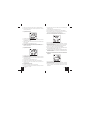
E. Weather Tendency Arrows
1. Along with the forecast icon there is a pressure tendency arrow.
2. There is one that points up (on the left side of the LCD) and one
that points down (on the right side of the LCD).
3. These arrows reflect current changes in the air pressure.
4. An arrow pointing up indicates that the air pressure is increasing
and the weather is expected to improve or remain good.
5. An arrow pointing down indicates that the air pressure is decreas-
ing and the weather is expected to become worse or remain poor.
6. No arrow means the pressure is stable.
Pressure trend arrow
7. A storm can be expected if there is a drop of 4 hPa or more in less
than 6 hours. The clouds with rain icon will be displayed and the
tendency arrow that points down will be flashing-indicating the storm
warning feature has been activated. The flashing will stop when
the air pressure stabilizes or begins to rise.
F. Barometric Air Pressure Reading
1. The actual barometric air pressure is displayed directly under the
weather forecast icon
2. The relative air pressure is calibrated by the user through the pro-
gramming mode.
3. Please Follow the programming instructions in section F of the De-
tailed Set Up Guide to set this feature.
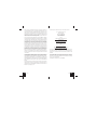
G. Air Pressure History Bar Chart
1. The bar graph shows in hPa (Hekto Pascal) the recorded air pres-
sure over the past 12-hours.
2. The horizontal axis shows the hours at increments of -12 hours, -9
hours, -6 hours, -3 hours, and 0 hours (current).
3. The vertical axis is set by hPa: the “0” on this axis represents the
current hPa, and + or - 1,3,5, or 7 shows (in hPa) how high or low
the past air pressure was as compared to the current one.
4. The “0” on the vertical axis indicates the current air pressure value.
5. The “0h” on the horizontal axis indicates the current hour, thus the
current air pressure also.
6. Each bar on the bar graph represents a value of 0.03 hPa, and
each bar also has a corresponding value on the verticle axis.
7. Air pressure trends can be determined by simply glancing at the
bar graph.
a. If the bars are rising (higher on the right than the left) then the
air pressure has a rising trend, and the weather should improve.
b. If the bars are dropping (lower on the right than the left) then the
air pressure has a falling trend, and the weather should worsen.
8. Multiply the two values to find past air pressure (note the + or - sign
of values on the verticle axis); i.e. 0.03 hPa x 3 = 0.09 hPa, now
add this value to the air pressure (in LCD 4) to evaluate what past
air pressures have been.
9. The bar chart will constantly scroll to avoid burnout of the LCD.
Note:
This feature cannot be turned off.
GB
P.17
GB
P.18

VII.
MOUNTING
Note:
Before permanently mounting, ensure that the indoor weather
station is able to receive signals from the transmitters and WWVB sig-
nal at the desired location. To achieve a true temperature reading,
avoid mounting the remote temperature sensor (or any sensor) where
direct sunlight can reach the remote sensor. We recommend that you
mount the remote sensor on a North-facing wall or under an eve. The
sending range of the remote temperature sensor is 330-ft (100m) how-
ever obstacles such as walls, concrete, and large metal objects can
reduce the range. Place all units in their desired location, and wait
approximately 15 minutes before permanently mounting to ensure that
there is proper reception. If the indoor weather station loses the signal
from the remote sensor, it will display the last temperature reading for
15 minutes. After 15 minutes of not receiving any signals, the remote
temperature will display “- -.-”.
A. Mounting the Remote Temperature Sensor
The remote temperature sensor can be mounted in two ways:
• with the use of screws
• using the adhesive tape
1. MOUNTING WITH SCREWS
a. Remove the mounting bracket from the remote temperature sensor.
b. Place the mounting bracket over the desired location.
c. Through the three screw holes of the bracket, mark the mounting
surface with a pencil.
d. Screw mounting bracket onto the mounting surface. Ensure that
the screws are flush with the bracket.
e. Insert the remote temperature sensor into the bracket.
2. MOUNTING WITH ADHESIVE TAPE
a. With a nonabrasive solution, clean and dry the back of the mount-
ing bracket and the mounting surface to ensure a secure hold. The
mounting surface should be smooth and flat.
b. Remove the protective strip from one side of the tape.
c. Adhere the tape to the designated area on the back of the mount-
ing bracket.
d. Remove the protective strip from the other side of the tape.
e. Position the remote temperature sensor in the desired location, en-
suring that the indoor weather station can receive the signal.
B. Mounting the WS-7394U Indoor Weather Station
The indoor weather station can be mounted in two ways:
• with the table stand
• on the wall with the use of a wall hanging screw (not included)
1. USING THE TABLE STAND
The indoor weather station comes with the table stand already mounted.
If you wish to use the table-stand all that is required is to place the
indoor weather station in an appropriate location.
2. WALL MOUNTING
a. Remove the table-stand. To do this, pull down on the stand from
the rear and rotate forward.
b. Fix a screw (not included) into the desired wall, leaving approxi-
mately 3/16 of an inch (5mm) extended from the wall.
c. Place the indoor weather station onto the screw using the hanging
hole on the backside.
d. Gently pull the indoor weather station down to lock the screw into
place.
MAINTENANCE AND CARE INSTRUCTIONS
A. Extreme temperatures, vibration, and shock should be avoided to
prevent damage to the units.
B. Clean displays and units with a soft, damp cloth. Do not use sol-
vents or scouring agents; they may mark the displays and casings.
C. Do not submerge in water.
D. Immediately remove all low powered batteries to avoid leakage and
damage.
E. Opening the casings invalidates the warranty. Do not try to repair
the unit. Contact La Crosse Technology for repairs.
TROUBLESHOOTING
Problem: The LCD is faint.
Solution:
1) Set the LCD contrast to a higher level.
2) Replace batteries.
Problem: No outdoor temperature/humidity is displayed.
Solution:
1) Remove all batteries, reinsert into the remote temperature sensor
first, then into the indoor weather station.
2) Place remote temperature sensor closer to the indoor weather
station.
3) Be sure all batteries are fresh.
4) No other interfering sources are being used (such as computer
monitors, TV sets, headphones, or speakers) in the vicinity. The
signal travels in a straight line, an electrical source near that “line”
may cause interference.
GB
P.19
GB
P.20

Problem: Temperature, humidity, or air pressure is incorrect.
Solution:
1) Check/Replace batteries.
2) If multiple remote sensors are in use, check location with corre-
sponding “boxed numbers.”
3) Move away from sources of heat/cold.
4) Adjust relative air pressure to a value from a reliable source (TV
radio, etc.).
5) The indoor weather station and remote sensors are calibrated at
the factory. If there is a consistent problem, please call La Crosse
Technology.
Problem: “- -” in humidity display.
Solution:
1) Humidity is below 1% or above 99%.
2) TX3U or TX3UP is used for remote temperature.
Problem: WWVB time and date will not set or update
Solution:
1) Wait until overnight for signal to be received
2) Move indoor weather station away from sources of electricity
3) Place indoor weather station in window facing Colorado
4) The first reception is most difficult, as the indoor weather station
needs five continual minutes of clear signal reception. After the
initial time/date set, the indoor weather station only requires one
full minute of clear reception each night.
SPECIFICATIONS
Indoor weather station recommended
operating temperature 32˚F to 122˚F (0˚C to 50˚C)
LCD contrast 8 levels (0-7)
Temperature measuring range
Indoor 14.2˚F to 139.8˚F with 0.2˚F resolution
(-9.9˚C to 59.9˚C with 0.1˚C resolution)
(“OFL” displayed if outside this range)
Outdoor -21.8˚F to 157.8˚F with 0.2˚F resolution
(-29.9˚C to 69.9˚C with 0.1˚C resolution)
(“OFL” displayed if outside this range)
Relative humidity range
Indoor 1% to 99% with 1% resolution,
indoor weather station displays “—.-”
if outside this range
Air pressure
Relative hPa (adjustable) 960 hPa to 1040 hPa
Relative inHg (adjustable) 28.35 inHg to 30.72 inHg
Sensitivity setting hPa 2 hPa to 4 hPa
Air pressure history For the past 12 hours
(0, -3, -6, -9, and -12 hours)
Data checking intervals
Indoor temperature Every 15 second
Indoor humidity Every 20 seconds
Outdoor temperature Every 5 minutes
Transmitter reading update (within sensor)
Outdoor temperature Every 1 minute
Tr ansmission frequency 433.92 MHz
Tr ansmission range 330 feet (100m)
Power supply
Indoor weather station: 2 x AA, IEC LR6, 1.5V batteries.
Remote temperature sensor: 2 x AA, IEC LR6, 1.5V batteries.
Dimensions (H x W x D)
Indoor weather station 8.75" x 4" x 1.5"
(222 x 102 x 38 mm)
Remote temperature sensor 5.04" x 1.57" x 0.9"
(128 x 40 x 23 mm)
WARRANTY INFORMATION
La Crosse Technology, Ltd provides a 1-year limited warranty on this
product against manufacturing defects in materials and workmanship.
This limited warranty begins on the original date of purchase, is valid
only on products purchased and used in North America and only to
the original purchaser of this product. To receive warranty service, the
purchaser must contact La Crosse Technology, Ltd for problem deter-
mination and service procedures. Warranty service can only be per-
formed by a La Crosse Technology, Ltd authorized service center. The
original dated bill of sale must be presented upon request as proof of
purchase to La Crosse Technology, Ltd or La Crosse Technology, Ltd’s
authorized service center.
La Crosse Technology, Ltd will repair or replace this product, at our
option and at no charge as stipulated herein, with new or recondi-
tioned parts or products if found to be defective during the limited war-
ranty period specified above. All replaced parts and products become
the property of La Crosse Technology, Ltd and must be returned to La
Crosse Technology, Ltd. Replacement parts and products assume
the remaining original warranty, or ninety (90) days, whichever is longer.
La Crosse Technology, Ltd will pay all expenses for labor and materi-
GB
P.21
GB
P.22

als for all repairs covered by this warranty. If necessary repairs are
not covered by this warranty, or if a product is examined which is not in
need or repair, you will be charged for the repairs or examination. The
owner must pay any shipping charges incurred in getting your La Crosse
Technology, Ltd product to a La Crosse Technology, Ltd authorized
service center. La Crosse Technology, Ltd will pay reasonable return
shipping charges to the owner of the product.
Your La Crosse Technology, Ltd warranty covers all defects in material
and workmanship with the following specified exceptions: (1) damage
caused by accident, unreasonable use or neglect (including the lack of
reasonable and necessary maintenance); (2) damage occurring dur-
ing shipment (claims must be presented to the carrier); (3) damage to,
or deterioration of, any accessory or decorative surface; (4) damage
resulting from failure to follow instructions contained in your owner’s
manual; (5) damage resulting from the performance of repairs or alter-
ations by someone other than an authorized La Crosse Technology,
Ltd authorized service center; (6) units used for other than home use
(7) applications and uses that this product was not intended or (8) the
products inability to receive a signal due to any source of interference..
This warranty covers only actual defects within the product itself, and
does not cover the cost of installation or removal from a fixed installation,
normal set-up or adjustments, claims based on misrepresentation by
the seller or performance variations resulting from installation-related
circumstances.
LA CROSSE TECHNOLOGY, LTD WILL NOT ASSUME LIABILITY
FOR INCIDENTAL, CONSEQUENTIAL, PUNITIVE, OR OTHER SIMI-
LAR DAMAGES ASSOCIATED WITH THE OPERATION OR MAL-
FUNCTION OF THIS PRODUCT. THIS PRODUCT IS NOT TO BE
USED FOR MEDICAL PURPOSES OR FOR PUBLIC INFORMATION.
THIS PRODUCT IS NOT A TOY. KEEP OUT OF CHILDREN’S
REACH.
This warranty gives you specific legal rights. You may also have other
rights specific to your State. Some States do no allow the exclusion of
consequential or incidental damages therefore the above exclusion of
limitation may not apply to you.
For warranty work, technical support, or information contact:
La Crosse Technology, Ltd
190 Main Street
La Crescent, MN 55947
Phone: 507.895.7095
Fax: 507.895.2820
e-mail:
support@lacrossetechnology.com
(warranty work)
(information on other products)
web:
www.lacrossetechnology.com
Questions ? Please see instruction video at
www.lacrossetechnology.info/7394
All rights reserved. This handbook must not be reproduced in any
form, even in excerpts, or duplicated or processed using electronic,
mechanical or chemical procedures without written permission of the
publisher.
This handbook may contain mistakes and printing errors. The infor-
mation in this handbook is regularly checked and corrections made in
the next issue. We accept no liability for technical mistakes or printing
errors, or their consequences.
All trademarks and patents are acknowledged.
GB
P.23
GB
P.24

INVENTAIRE
1. La station météo WS-7394U
2. Le capteur de température (température/humidité)) distant TX6U
3. Manuel d’instructions et fiche de garantie
ÉQUIPEMENT SUPPLÉMENTAIRE (non-fourni)
1. Cinq piles neuves 1,5V de type AA.
2. Une vis de fixation murale (en option)
APROPOS DE L’ÉMETTEUR WWVB (Heure radiocommandée)
L’émetteur radio WWVB de la NIST (National Institute of Standards
and Technology-Time and Frequency Division) WWVB est situé à Ft.
Collins dans le Colorado et émet un signal horaire exact en continu
sur 60 kHz à travers les États-Unis. Le signal peut être réceptionné
dans un rayon de 3 200 km à l’aide de l’antenne incorporée à la sta-
tion météo. Cependant, cette réception est très restreinte pendant la
journée, à cause des effets de l’ionosphère terrienne. Chaque nuit,
lorsque les conditions de réception sont optimales, la station météo
recherchera le signal. L’émetteur radio WWVB prend son signal à partir
de l’horloge atomique de la NIST à Boulder, Colorado. Une équipe de
physiciens en atomique mesure en continu chaque seconde de chaque
jour à une précision de dix-milliardièmes de seconde par jour. Ces
physiciens ont établi la norme internationale pour une seconde, comme
TABLE DES MATIÈRES
Sujet Page
Inventaire/ Équipement supplémentaire 26
A propos du WWVB 26
Guide de paramétrage rapide 27
Guide de paramétrage détaillé
Installation des Piles 28
Séquence de mise en route 29
Explication des informations affichées à l’écran LCD 31
Disposition des touches de fonction 32
Mode Programmation
Récapitulatif de la séquence de programmation 32
Contraste de l’écran LCD 32
Fuseau horaire 33
Heure d’été 33
Activation/désactivation de l’heure radiocommandée 34
Format 12/24 H 34
Réglage manuel de l’heure/date 35
Unités de mesure de la température (˚C/˚F) 36
Unités de mesure de la pression atmosphérique (inHg/hPa)
37
Pression atmosphérique relative 37
Sensibilité des prévisions météo 38
Fonctionnalités et fonctionnement
Relevés minimum/maximum de température/humidité 39
Capteurs de température/humidité distants multiples 40
Icône du confort 41
Prévisions météo et indicateurs de tendance météo 41
Icônes météo 41
Flèches de tendance météo 42
Relevé de la pression atmosphérique barométrique 42
Historique de la pression atmosphérique 42
Fixation 43
Entretien et soin 44
Dépistage des pannes 45
Caractéristiques techniques 46
Informations sur la garantie 47
F
P.25
F
P.26

étant 9 192 631 770 vibrations d’un atome de Césium-133 dans un
vacuum. Pour plus d’informations sur le WWVB et l’horloge atomique,
visitez le site web du NIST
http: //www.boulder.nist.gov/timefreq/sta-
tions/wwvb.htm
GUIDE DE PARAMÉTRAGE RAPIDE
Conseil :
Utilisez des piles alcalines de marque et évitez les piles
rechargeables.
1. Placez le capteur de température distant à 1m - 1m 50 de la station
météo intérieure.
2. Les piles doivent être retirées des deux unités pendant 15 minutes.
3. Insérez en premier les piles du capteur de température distant,
puis celles de la station météo intérieure.
(Tous les capteurs de température distants doivent être initialisés
avant la station météo intérieure)
4. N’APPUYEZ SUR AUCUNE TOUCHE PENDANT 15 MINUTES.
Pendant ce temps, la station météo intérieure et le capteur de
température commenceront à ‘dialoguer’, la station affichant la
température et l’humidité intérieures et la température extérieure. Si la
station météo n’affiche pas toutes ces informations dans les 15 minutes,
répétez la procédure de paramétrage détaillée ci-dessus. Lorsque les
informations ont été affichées pendant 15 minutes, vous pouvez in-
staller vos capteurs à l’extérieur et régler l’heure.
Le capteur de température distant doit être placé dans un endroit sec
et ombragé. Le rayon d’émission du capteur de température distant
est de 100 mètres. Tout mur se trouvant sur la trajectoire du signal
réduira sa portée. Un mur extérieur ou une fenêtre peut réduire la
portée de 6 à 9 mètres, un mur intérieur de 3 à 6 mètres. La distance,
en tenant compte des réductions, ne doit pas excéder 100 mètres en
ligne droite.
REMARQUE :
Le brouillard et la brume n’auront aucun effet nuisible
sur le capteur de température distant mais la pluie doit être évitée.
Pour terminer l’installation de votre station météo intérieure une fois
les 15 minutes écoulées, référez-vous au Guide de paramétrage
détaillé.
Note:
Le capteur de température distant émet un signal toutes les 3
minutes ; après installation des piles, la station météo intérieure
recherchera un signal pendant 5 minutes. Si, après 5 minutes, aucune
température n’est affichée à la section EXTÉRIEUR de l’écran LCD,
vérifiez que les unités sont dans le rayon de réception l’un de l’autre
ou répétez l’installation des piles.
GUIDE DE PARAMÉTRAGE DETAILLE
I. Installation des piles
Les piles s’enclenchent fermement. Afin d’éviter tout problème au
démarrage, vérifiez qu’elles restent bien en place. Aussi, prenez soin
d’installer les piles du capteur de température en premier, puis celles
de la station météo. La mise en route initiale doit être effectuée avec la
station météo intérieure et le capteur de température dans la même
pièce. Les unités ne doivent être fixées en place que lorsque la
réception du signal a été vérifiée.
A. Capteur de température et d’humidité distant
1. Retirez le support de fixation. Le support se détache et s’attache
facilement.
2. Retirez le couvercle du compartiment à piles en le faisant glisser
vers le bas.
3. Installez 2 piles de type AA en respectant la polarité. Les piles
s’enclenchent fermement (afin d’éviter tout problème au démarrage,
vérifiez qu’elles restent bien en place).
4. Remplacez le couvercle du compartiment en le faisant glisser vers
le haut. Assurez-vous de sa bonne fermeture.
le couvercle du
compartime
F
P.27
F
P.28

B. Station météo intérieure
1. Retirez le couvercle du compartiment à piles (le couvercle porte un
texte en blanc).
2. Insérez deux piles alcalines de type AA en respectant la polarité.
3. N’appuyez sur aucune touche pendant dix minutes minimum. Si
une touche est pressée avant que la station ne reçoive les informa-
tions du capteur TX6U, aucune donnée ne sera reçue de ce capteur
jusqu’à ce que celui-ci soit réinitialisé.
4. Remettez le couvercle du compartiment à piles.
II. Séquence de mise en route
A. Mise en route initiale
1. Immédiatement après l’installation des piles, l’écran LCD s’allume
momentanément en entier.
2. Toutes les informations s’affichent alors en mode normal, l’heure
par défaut étant “12:00” et la date par défaut “WE.1” (l’année est
2004).
3. La température et l’humidité intérieures et la pression atmosphérique
barométrique (29,91 inHg HR) seront également affichées.
4. Une icône “satellite” s’affiche en bas de l’écran LCD à gauche de la
température extérieure pour indiquer que la station météo intérieure
recherche le signal provenant du capteur de température distant.
La température distante devrait s’afficher dans les cinq minutes-
dans le cas contraire, retirez toutes les piles des unités, puis répétez
la procédure d’installation en commençant par le capteur de
température distant, suivi de la station météo intérieure.
B. Réception du signal WWVB
1. Lorsque les piles sont installées dans la station météo intérieure,
celle-ci commence automatiquement à rechercher le signal WWVB.
Si un bon signal est reçu (peu probable le jour dans la plupart des
localités), l’indicateur de réception WWVB (en forme de tour)
clignote. Il faut cinq bonnes minutes de réception d’un signal
suffisamment fort, pour permettre à la station météo intérieure de
régler l’heure, les minutes, les secondes, le mois, la date et l’année.
Si la réception n’est pas complétée dans les dix minutes, la recher-
che sera annulée et retentée automatiquement toutes les deux
heures jusqu’à réception définitive du signal.
2. Le signal est émis uniquement depuis Ft. Collins, Colorado et
ressemble à un signal radio AM. Les perturbations atmosphériques
telles qu’orages, taches solaires et même le rayonnement du soleil
peuvent entraver le signal.
3. Pour maximiser les chances de réception, placez la station météo
intérieure à une fenêtre, orientée en direction du Colorado et à
deux mètres minimum de tout appareil électrique (ordinateurs,
téléviseurs, réfrigérateurs, etc.). Ne déplacez pas la station météo
intérieure pendant la recherche du signal.
4. L’heure et la date peuvent être réglées manuellement. Lorsque le
signal est reçu, l’heure et la date réglées manuellement seront
remplacées en fonction du fuseau horaire.
5. Lorsque l’heure et la date sont réglées, la station météo intérieure
recherchera le signal toutes les nuits à minuit afin de maintenir sa
précision (l’heure d’été est appliquée automatiquement). Si le sig-
nal a été reçu au cours des 24 dernières heures, l’indicateur de
réception s’affiche.
F
P.29
F
P.30

III. Explication des informations affichées à l’écran LCD
A. Le schéma ci-dessous présente les fonctionnalités de l’écran LCD.
B. La station météo intérieure fonctionne en plusieurs modes. L’écran
LCD est présenté ici en mode normal ; les données affichées sur
votre station météo seront différentes selon vos paramètres et les
conditions locales.
IV.Disposition des touches de fonction
A. Le schéma ci-dessous présente les quatre touches de fonction
utilisées pour la programmation et le fonctionnement de votre sta-
tion météo intérieure
V. Mode Programmation
Le mode programmation est disposé de manière à permettre une
programmation individuelle de chaque fonction ou une programmation
globale de la station météo intérieure. La programmation globale
s’effectue normalement à l’installation initiale et, dans ce cas, les étapes
1,2 et 3 de chaque rubrique de programmation ne sont pas prises en
compte. Vous pouvez quitter le mode programmation à tout moment
en appuyant sur la touche “CH” ou en attendant la temporisation de 15
secondes.
A. Récapitulatif de la séquence de programmation
1. Contraste LCD 2. Fuseau horaire 3. Heure d’été
4.
Activation/désactivation
5. Format 12/24 H 6. Heure
de l’heure radiocommandée
7. Minutes 8. Année 9. Mois
10.Date 11.˚F/˚C 12.inHg/hPa
13.Pression atmosphérique 14.Sensibilité des
relative prévisions météo
B. Contraste de l’écran LCD
1. Appuyez sur la touche “SET” pendant cinq secondes.
2. “lcd” s’affiche en haut de l’écran, accompagné d’un chiffre clignotant.
3. Appuyez sur la touche “OUT/+” pour sélectionner le niveau de
contraste désiré.
Indicateur de
réception WWVB
Affichage de la
date
Heure
radiocommandé
Icône du confort
Affichage de la
température et de
l’humidité
intérieures
Indicateur de
tendance de la
pression
atmosphérique
Icône de prévision
Pression
atmosphérique
Histogramme de la
pression
atmosphérique sur
les 12 dernières
heures
Affichage de la
température
extérieure
Identifiant du
capteur distant (3
maximum)
F
P.31
F
P.32

4. Appuyez sur la touche “SET” pour confirmer le niveau du contraste
et passer en mode réglage du fuseau horaire.
C. Fuseau horaire
1. Appuyez sur la touche “SET” pendant cinq secondes.
2. “lcd” s’affiche en haut de l’écran, accompagné d’un chiffre clignotant.
3. Appuyez de nouveau sur la touche “SET” pour avancer à la
programmation du fuseau horaire.
4. Un chiffre clignote à gauche de la lettre “h” en haut de l’écran, sous
l’affichage de l’heure.
5. Appuyez sur la touche “OUT+” pour sélectionner le fuseau horaire.
6. Appuyez sur la touche “SET” pour confirmer le fuseau horaire et
passer à la programmation de l’heure d’été.
D. Heure d’été
1. Appuyez sur la touche “SET” pendant cinq secondes.
2. “lcd” s’affiche en haut de l’écran, accompagné d’un chiffre clignotant.
3. Appuyez encore deux fois sur la touche “SET” pour avancer à la
programmation de l’heure d’été.
4. “DST” s’affiche au-dessus de l’affichage de la température/humidité
intérieure et “ON” ou “OFF” clignote juste au-dessus.
5. Appuyez sur la touche “OUT/+” pour activer (ON) ou désactiver
(OFF) l’heure d’été.
Remarque :
Certaines régions (dont l’Arizona et une partie de l’Indiana)
n’appliquent pas l’heure d’été.
6. Appuyez sur la touche “SET” pour confirmer l’activation ou la
désactivation de l’heure d’été et passer en mode activation/
désactivation de l’heure radiocommandée.
E. Activation (ON)/désactivation (OFF) de l’heure
radiocommandée
1. Appuyez sur la touche “SET” pendant cinq secondes.
2. “lcd” s’affiche en haut de l’écran, accompagné d’un chiffre clignotant.
3. Appuyez encore trois fois sur la touche “SET” pour avancer à
l’activation/désactivation de l’heure radiocommandée.
4. “RCC” s’affiche au-dessus de l’affichage de la température/humidité
intérieure et “ON” ou “OFF” clignote juste au-dessus.
5. Appuyez sur la touche “OUT/+” pour activer (ON) ou désactiver
(OFF) l’heure radiocommandée.
6. Appuyez sur la touche “SET” pour confirmer l’activation ou la
désactivation de l’heure radiocommandée et passer en mode
programmation du format 12/24 H.
F. Format 12/24 H
1. Appuyez sur la touche “SET” pendant cinq secondes.
2. “lcd” s’affiche en haut de l’écran, accompagné d’un chiffre clignotant.
3. Appuyez encore quatre fois sur la touche “SET” pour avancer à la
programmation du format 12/24 H.
4. “12h” ou “24h” clignote au-dessus de l’affichage de la température/
humidité intérieure.
5. Appuyez sur la touche “OUT/+” pour sélectionner soit le format 12
H, soit le format 24 H.
Remarque :
En format 12H et entre midi et minuit, “PM” s’affiche à
gauche de l’heure. En dehors de ces heures, rien n’est affiché. Prenez
soin de sélectionner l’heure correspondante, AM ou PM, afin d’assurer
la réception automatique.
F
P.33
F
P.34

6. Appuyez sur la touche “SET” pour confirmer le format 12H ou 24H
et passer en mode réglage manuel de l’heure.
G. Réglage manuel de l’heure
Le signal WWVB remplace tous les réglages manuels de l’heure et de
la date. L’heure sera en fonction du fuseau horaire sélectionné.
1. Appuyez sur la touche “SET” pendant cinq secondes.
2. “lcd” s’affiche en haut de l’écran, accompagné d’un chiffre clignotant.
3. Appuyez encore cinq fois sur la touche “SET” pour avancer au
réglage manuel de l’heure.
4. Le chiffre des heures clignote en haut de l’écran.
5. Appuyez sur la touche “OUT/+” pour régler l’heure.
6. Appuyez sur la touche “SET” pour confirmer l’heure et passer au
réglage des minutes.
H. Réglage manuel des minutes
1. Appuyez sur la touche “SET” pendant cinq secondes.
2. “lcd” s’affiche en haut de l’écran, accompagné d’un chiffre clignotant.
3. Appuyez encore six fois sur la touche “SET” pour avancer au réglage
manuel des minutes.
4. Le chiffre des minutes clignote en haut de l’écran.
5. Appuyez sur la touche “OUT/+” pour régler les minutes.
6. Appuyez sur la touche “SET” pour confirmer les minutes et passer
au réglage de l’année.
I. Réglage manuel de l’année
1. Appuyez sur la touche “SET” pendant cinq secondes.
2. “lcd” s’affiche en haut de l’écran, accompagné d’un chiffre clignotant.
3. Appuyez encore sept fois sur la touche “SET” pour avancer au
réglage manuel de l’année.
4. L’année clignote en dessous de l’affichage de l’heure.
5. Appuyez sur la touche “OUT/+” pour sélectionner l’année.
6. Appuyez sur la touche “SET” pour confirmer l’année et passer au
réglage du mois.
J. Réglage manuel du mois
1. Appuyez sur la touche “SET” pendant cinq secondes.
2. “lcd” s’affiche en haut de l’écran, accompagné d’un chiffre clignotant.
3. Appuyez encore huit fois sur la touche “SET” pour avancer au
réglage manuel du mois.
4. Le mois clignote en dessous de l’affichage de l’heure.
5. Appuyez sur la touche “OUT/+” pour sélectionner le mois.
6. Appuyez sur la touche “SET” pour confirmer le mois et passer au
réglage de la date.
K. Réglage manuel de la date
1. Appuyez sur la touche “SET” pendant cinq secondes.
2. “lcd” s’affiche en haut de l’écran, accompagné d’un chiffre clignotant.
3. Appuyez encore neuf fois sur la touche “SET” pour avancer au
réglage manuel de la date.
4. La date clignote en dessous de l’affichage de l’heure.
5. Appuyez sur la touche “OUT/+” pour sélectionner la date.
6. Appuyez sur la touche “SET” pour confirmer la date et passer à la
programmation des unités de température.
L. Unités de mesure de la température (˚F ou ˚C)
1. Appuyez sur la touche “SET” pendant cinq secondes.
2. “lcd” s’affiche en haut de l’écran, accompagné d’un chiffre clignotant.
F
P.35
F
P.36

3. Appuyez encore dix fois sur la touche “SET” pour avancer à la
programmation des unités de mesure de la température.
4. ˚F ou ˚C clignote en haut de l’écran.
5. Appuyez sur la touche “OUT/+” pour sélectionner les unités de
mesure de la température.
6. Appuyez sur la touche “SET” pour confirmer les unités de mesure
de la température et passer à la programmation des unités de
mesure de la pression atmosphérique.
M. Unités de mesure de la pression atmosphérique (inHg/hPa)
1. Appuyez sur la touche “SET” pendant cinq secondes.
2. “lcd” s’affiche en haut de l’écran, accompagné d’un chiffre clignotant.
3. Appuyez encore onze fois sur la touche “SET” pour avancer à la
programmation des unités de mesure de la pression atmosphérique.
4. inHg ou hPa clignote en haut de l’écran.
5. Appuyez sur la touche “OUT/+” pour sélectionner les unités de
mesure de la pression atmosphérique.
6. Appuyez sur la touche “SET” pour confirmer les unités de mesure
de la pression atmosphérique et passer à la programmation de la
pression relative.
N. Pression atmosphérique relative
1. Appuyez sur la touche “SET” pendant cinq secondes.
2. “lcd” s’affiche en haut de l’écran, accompagné d’un chiffre clignotant.
3. Appuyez encore onze fois sur la touche “SET” pour avancer à la
programmation de la pression relative.
4. La pression atmosphérique barométrique clignote au centre de
l’écran juste en dessous de l’icône de prévision météo
5. Appuyez sur la touche “OUT/+” ou “IN” pour sélectionner l’unité de
mesure de la pression atmosphérique.
6. Appuyez sur la touche “SET” pour confirmer la pression relative et
passer à la programmation de la sensibilité des prévisions météo.
O. Sensibilité des prévisions météo
1. Appuyez sur la touche “SET” pendant cinq secondes.
2. “lcd” s’affiche en haut de l’écran, accompagné d’un chiffre clignotant.
3. Appuyez encore treize fois sur la touche “SET” pour avancer à la
programmation de la sensibilité des prévisions météo.
4. Les deux flèches de tendance de la pression atmosphérique
clignotent de part et d’autre de l’icône de prévision et un chiffre
clignotant s’affiche sous l’icône.
5. Appuyez sur la touche “OUT/+” pour sélectionner le niveau de
sensibilité des prévisions météo.
Remarque :
La pression atmosphérique barométrique est souvent
présentée en tant que “pression atmosphérique relative “. Ce relevé
est basé sur une combinaison de la pression atmosphérique absolue
et l’altitude. En général, la pression atmosphérique diminue avec
l’altitude. Le relevé de pression atmosphérique relative prend en compte
la pression atmosphérique dans des localités avoisinantes afin de
permettre une prévision conforme. Seul le relevé de pression
atmosphérique relative peut être étalonné, et non celui de la pression
atmosphérique absolue de la station météo.
6. Appuyez sur la touche “SET” pour confirmer le niveau de sensibilité
des prévisions météo.
LA PROGRAMMATION MANUELLE EST MAINTENANT TERMINÉE
F
P.37
F
P.38
La page est en cours de chargement...
La page est en cours de chargement...
La page est en cours de chargement...
La page est en cours de chargement...
La page est en cours de chargement...
La page est en cours de chargement...
La page est en cours de chargement...
La page est en cours de chargement...
La page est en cours de chargement...
La page est en cours de chargement...
La page est en cours de chargement...
La page est en cours de chargement...
La page est en cours de chargement...
La page est en cours de chargement...
La page est en cours de chargement...
La page est en cours de chargement...
La page est en cours de chargement...
La page est en cours de chargement...
La page est en cours de chargement...
-
 1
1
-
 2
2
-
 3
3
-
 4
4
-
 5
5
-
 6
6
-
 7
7
-
 8
8
-
 9
9
-
 10
10
-
 11
11
-
 12
12
-
 13
13
-
 14
14
-
 15
15
-
 16
16
-
 17
17
-
 18
18
-
 19
19
-
 20
20
-
 21
21
-
 22
22
-
 23
23
-
 24
24
-
 25
25
-
 26
26
-
 27
27
-
 28
28
-
 29
29
-
 30
30
-
 31
31
-
 32
32
-
 33
33
-
 34
34
-
 35
35
-
 36
36
-
 37
37
-
 38
38
-
 39
39


La Crosse Technology WS-7394U Manuel utilisateur
- Catégorie
- Stations météo
- Taper
- Manuel utilisateur
dans d''autres langues
Documents connexes
-
 La Crosse Technology WS-8035U-IT Manuel utilisateur
-
LA CROSS TECHNOLOGY WS-7394U-IT Le manuel du propriétaire
-
La Crosse Technology WS-8025U Manuel utilisateur
-
-
 LA CROSS TECHNOLOGY WS-8025SU Manuel utilisateur
-
 La Crosse Technology WS-8025SU Manuel utilisateur
-
LA CROSS TECHNOLOGY WS-7017U-IT Le manuel du propriétaire
-
 La Crosse Technology WS-7215U Manuel utilisateur
-
LA CROSS TECHNOLOGY WS-9037U-IT Manuel utilisateur
-
 La Crosse Technology WS-9118U Manuel utilisateur


