
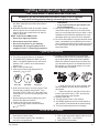
ATTENTION
Installation and service must be performed by
a qualified agency, individual, firm, corporation,
or company, experienced in the installation, re
-
pair, and servicing of this type of gas appliance.
Do not modify, alter or tamper with any part of
this heater, control, or logs.
— Do not store or use gasoline or other flam-
mable vapors and liquids in the vicinity of this
or any other appliance.
— WHAT TO DO IF YOU SMELL GAS
• Do not try to light any appliance.
• Do not touch any electrical switch; do not
use any phone in your building.
• Immediately call your gas supplier from a
neighbor’s phone. Follow the gas supplier’s
instructions.
• If you cannot reach your gas supplier, call
the fire department.
Installation and Operating
Instructions
W A R N I N G
If the information in this manual is not followed exactly, a fire or explosion may result, causing property
damage, injury or loss of life.
Tested and listed to ANSI Z21.11.2b.2004, Unvented Heaters,
and Z21.60b-2004; CSA 2.26b-2004 Decorative Gas Appliances
for Installation in Solid-Fuel Burning Fireplaces.
W A R N I N G
CARBON MONOXIDE POISONING MAY LEAD TO DEATH.
When used without fresh air, vent-free log sets may give off carbon monoxide, an odorless, poisonous gas.
Some people - pregnant women, people with heart or lung disease, anemia, or persons under the influence of alcohol, and
persons at high altitudes are more affected by carbon monoxide than others.
Early signs of carbon monoxide poisoning resemble the flu - headache, dizziness, and/or nausea. If you have these signs, the
heater may not be installed or working properly. GET FRESH AIR AT ONCE!
Have the heater serviced before using it again.
Vent-Free Gas Log Sets*
Models: UVLC18RN, UVLC24RN, UVLC30RN (Natural Gas)
UVLC18RP, UVLC24RP, UVLC30RP (Propane)
CE RTI FI E D
D
E
S
I
G
N
C
E
R
T
I
F
I
E
D
20000333 7/06 Rev. 12
*These logsets are not for exterior use.
This appliance may be installed in an aftermar-
ket, permanently located, manufactured (mobile)
home, where not prohibited by local codes.
This appliance is only for use with the type of gas
indicated on the rating plate. This appliance is
not convertible for use with other gases.
INSTALLER PLEASE NOTE:
DO NOT begin installation of this gas logset
until all instructions have been read and under-
stood.
INSTALLER: Leave this manual with the appliance.
CONSUMER: Retain this manual for future reference.

2 UVLC Series
General Information
IN ORDER TO ASSURE A SAFE AND EFFECTIVE
INSTALLATION, ONLY A QUALIFIED SERVICE
PERSON WHO IS FAMILIAR WITH THE BUILDING
CODES AND INSTALLATION TECHNIQUES AP
-
PROPRIATE TO YOUR AREA MAY INSTALL AND
SERVICE THIS APPLIANCE.
• In order to avoid any possible gas leaks, apply pipe joint com-
pound to all non-flared, threaded connections involved in this
installation. For propane, the joint compound must be resistant
to the corrosive action of propane.
• To check for leaks, always use a soapy water solution or a
sniffer. Never test by using an open flame.
• The area around the gas logset must be free of all combus-
tible materials, especially gasoline or other highly flammable,
vapor producing liquids.
• Due to high temperatures, locate this logset away from both
high traffic areas and furniture and draperies.
• Children and adults alike should be aware of the high surface
temperatures; to avoid the risk of burns or ignition of clothing
they should stay away.
• Do not touch any part of the logset other than the controls
while it is operating or immediately after you turn it off.
• Supervise young children and pets carefully when they are in
the room where the logset is operating.
• Do not place clothing or other flammable material on or near
the logset.
• Make sure that any safety screen or guard, removed during
servicing, has been replaced before you use the logset.
• Do not, under any circumstances, install the logset in any
bedroom, bathroom, other small, enclosed room, mobile home
or recreational vehicle.
• Do not install the logset in a drafty area or use it with any
after-market blower system that may cause drafting and conse-
quently alter the flame pattern.
• It is imperative that you keep clear all burner areas, control
compartments and passageways for circulating air.
• Do not move the logset in any way that might dislodge the
logs from their fixed positions. If you bump the logset check to
see if you have dislodged anything.
• Vent-free logsets require additional fresh air. You may supply
additional fresh air with any combination of: opening windows or
doors; or by operating a central furnace blower or exhaust fan.
• Provide adequate clearances around air openings into the
combustion chamber and adequate accessibility clearance for
servicing and proper operation. NEVER obstruct the front open-
ing of the fireplace.
• Avoid propane tank dropping below 25% full. This will help
prevent soot from occurring.
The Logsets have been designed and tested to operate
safely when installed according to the installation instruc-
tions contained in this manual. Read all instructions
before starting the installation.
• The vent-free gas logset must be installed only in a fireplace
constructed of noncombustible material.
• These logsets are not for exterior use.
• The logset should be inspected before use and at least an-
nually thereafter. More frequent cleaning may be necessary
because of excessive lint from carpeting or bedding material.
• In the United States, the installation and operation must
conform to local codes or, in the absence of local codes, with
the National Fuel Gas Code, ANSI Z223.1/NFPA 54, latest edi
-
tion and with the National Electrical Code, ANSI/NFPA70 (latest
edition). State or local codes may only allow operation of this
appliance in a vented configuration. Check your state or local
codes. In Canada check local province for proper use or CSA-
B149. Refer to pages 7 and 8 for installation details.
• The gas logset and its individual shutoff valve must be dis-
connected from the gas supply piping system during any pres-
sure testing of that system at test pressures in excess of 1/2
p.s.i.g. (3.5 kPa.) The gas logset must be isolated from the gas
supply piping system by closing its individual manual shutoff
valve during any pressure testing of the gas supply piping sys-
tem at test pressures equal to or less than 1/2 p.s.i.g. (3.5 kPa.)
• Do not, under any circumstances, burn solid fuel (wood, pa-
per, coal) in the masonry or UL127 factory built fireplace where
you have installed your logset. Do not use it for cooking. Put
nothing on top of the logs.
• The logset must be compatible with its fuel. Natural gas
requires different hardware than propane. Never attempt to use
natural gas with a propane logset or vice versa.
• For a propane burning logset, the supply tank must include a
high to low gas pressure regulator. The tank must be outdoors.
Do not, under any circumstances, locate supply tanks inside
any structure.
• The fireplace must include a screen made of chain mesh or
a similar material. You must keep the screen closed at all times
during the operation of the logset; it will protect you in the event
of an explosion.
• WARNING: If the fireplace contains glass doors, they must
remain fully open at all times during the operation of the logset,
allowing combustion air to circulate.
Proposition 65 Warning:
Fuels used in gas, wood-
burning or oil fired appliances, and the products of
combustion of such fuels, contain chemicals known to
the State of California to cause cancer, birth defects
and other reproductive harm.
California Health & Safety Code Sec. 25249.6

3
UVLC Series
WARNING
This appliance is for installation in a solid-fuel
burning masonry, fireplace with a working flue,
a U.L.-127 listed manufactured solid-fuel burn-
ing fireplace, in any Majestic ventless firebox,
or in any listed ventless firebox enclosure
certified to I.A.S. U.S. Requirement 2-97 or ANSI
Z21.91.
NOTICE
This is an unvented gas-fired heater. It uses air
(oxygen) from the room in which it is installed. Pro-
visions for adequate combustion and ventilation air
must be provided. Refer to pages 5 and 6.
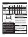
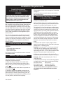
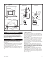
Installation Requirements
The fireplace must meet the minimum dimensions listed below. (Fig. 1) Do not install the logset if the fireplace does
not meet these minimums.
Pressure Test Points
The gas control is equipped with a captured screw-type
pressure test point, therefore it is not necessary to pro-
vide a 1/8” test point upstream of the control.
Odor During Operation
Neither natural gas nor propane gas give off an odor
when burned. The nature of a vent free combustion
system, however, is such that odors may occasionally be
produced during heater operation when impurities exist
in the immediate area. Cleaning solutions, paint, sol-
vents, cigarette smoke, candles, adhesives, new carpet
or textiles, etc., all can create fumes. These fumes may
mix with combustion air and can create odor. Such odors
will disappear over time, however, the condition can be
alleviated by opening a window or otherwise providing
additional ventilation to the area.
Min. Fireplace Dimensions
A B C D
Logset Gas Front Rear Overall Overall Pressure (w.c.) Manifold Min. Input Max. Input Setting
Width Width Depth Height Min. Max. Pressure BTU/hr BTU/hr Front Rear
18” UVLC18RN 30” 17” 15” 18” 5.5” 14.0” 3.5” 22,000 30,000 3/8” 3/8”
Open Open
24” UVLC24RN Natural 33” 20” 15” 18” 5.5” 14.0” 3.5” 29,000 39,000 Full 3/8”
Open Open
30” UVLC30RN 36” 25” 15” 18” 5.5” 14.0” 3.5” 29,000 39,000 Full 3/8”
Open Open
18” UVLC18RP 30” 17” 15” 18” 11.0” 14.0” 11.0” 22,000 30,000 Full Full
Open Open
24” UVLC24RP Propane 33” 20” 15” 18” 11.0” 14.0” 11.0” 29,500 39,000 3/8” Full
Open Open
30” UVLC30RP 36” 25” 15” 18” 11.0” 14.0” 11.0” 29,500 39,000 3/8” Full
Open Open
Inlet Supply Air Shutter
A. Front width B. Rear width
C. Depth D. Height
Fig. 1 Minimum fireplace dimensions.
FD370-2
Fireplace
dimensions/vl18
3/25/99
A
B
D
C
FD370-2
High Elevations
Input ratings are shown in BTU per hour and are
certified without deration from elevations up to
4,500 feet (1,370m) above sea level.
Nuisance outages may occur at altitudes above
4,500 feet (1,370m) if dirt, dust, lint and/or cobwebs
are allowed to accumulate on burner and/or ODS
pilot. Monthly inspection and cleaning is recom-
mended for altitudes above 4,500 feet (1,370m)
For elevations above 4,500 feet (1,370m) in USA,
installations must be in accordance with the cur-
rent ANSI Z223.1/NFPA 54 and/or local codes hav-
ing jurisdiction.
In Canada, please consult provincial and/or local
authorities having jurisdiction for installations at
elevations above 4,500 feet (1,370m)

4 UVLC Series
Planning
Planning the installation is an important first step. It will
save time and money later in the actual installation. In
planning the installation, consider:
• Where the heater will be located.
• All components needed to complete the installation.
• DO NOT use this heater in sleeping quarters, mobile
homes, or in recreational vehicles.
• Installation and repair should be done by a qualified
service person.
• DO NOT use this heater if any part has been under
water. Immediately call a qualified technician to inspect
the appliance and replace any part of the control sys-
tem and any gas control which has been under water.
• When used as an unvented heater, always ensure
that there is adequate ventilation from the room where
the appliance is operating. This appliance is equipped
with and ODS (oxygen depletion sensor) pilot light safe-
ty system designed to shut off the appliance if enough
fresh air is not available.
THIS APPLIANCE MUST NOT BE USED WITH GLASS
DOORS IN A CLOSED POSITION .
Keep the burner and control compartment clean. See
installation and operating instructions supplied with the
heater.
WARNING: During manufacturing, fabricating, and
shipping, various components of this appliance are
treated with certain oils, films, or bonding agents.
These chemicals are not harmful, but may produce
annoying smoke and smells as they are burned off
during the initial operation of the appliance, pos-
sibly causing headaches or eye or lung irritation.
This is a normal and temporary occurrence. The
initial break-in operation should last 2-3 hours with
the burner at its highest setting. Provide maximum
ventilation by opening windows, doors, and the
chimney flue to allow odors to dissipate. Any odors
remaining after this initial break-in will be slight and
will disappear with continued use.
This appliance operates as an unvented domestic room
heater when fitted to a masonry or factory-built wood-
burning fireplace with the flue damper closed, or as
a decorative appliance when the flue damper is fully
open. It must not be used for any other purpose and
must be fitted in a masonry or factory-built fireplace or
ventless firebox enclosure.
State, provincial or local codes may only allow opera-
tion of this appliance in a vented configuration. Check
your state, provincial or local codes. If unvented room
heaters are not permitted, the fireplace vent damper
must be locked open at the minimum vent area required
by local codes or by the National Fuel Gas Code (ANSI
Z223.1/NFPA 54, latest edition) and CSA B149 Installa-
tion Codes for Gas Burning Appliances.
When installed as a Decorative Gas Appliance for
installation in a solid-fuel burning fireplace, a mini
-
mum permanent free opening of 29 square inches
must be maintained with a fixed damper stop pro-
vided with the appliance. Minimum flue size for this
appliance is 29 square inches.
Installation Precautions
1. This vent-free gas appliance and its components
have been tested and will operate safely when installed
in accordance with this Installation Manual. Read all
instructions before starting the installation, and follow
these instructions carefully \ installation to maximize the
appliance’s benefit and safety. Failure to follow them
will void your warranty and may present a fire hazard.
2. After opening the carton, refer to Parts Identification
on Page 15 and 16, and remove the various parts.
Report to your dealer if any parts were damaged in
shipment.
The CFM Corporation warranty will be voided by,
and CFM Corporation disclaims any responsibility
for, the following actions:
• Installation of any damaged appliance.
• Modification of the appliance.
• Installation other than as instructed by
CFM Corporation.
• Improper positioning of the gas logs.
• Installation and/or use of any component
part or accessory not manufactured or approved
by CFM Corporation, not withstanding any inde-
pendent testing laboratory or other third-party
approval of such component part or accessory.
Any such action may create a possible fire hazard.
Consult your local building codes.
This heater shall not be installed in a confined
space unless provisions are provided for adequate
combustion and ventilation air.
WARNING
Improper installation, adjustment, alteration, ser-
vice, or maintenance can cause injury of proper-
ty damage. Refer to this manual. For assistance
or additional information, consult a qualified
installer, service agency, or the gas supplier.

5
UVLC Series
Fresh Air Requirements
for Combustion and Ventilation
If your home meets all of the above criteria, you must
provide additional fresh air for the appliance as detailed
on Page 6.
If your home does not meet the above criteria, follow
the procedure below.
Determine If You Have a Confined
or Unconfined Space
Use the following formula to determine if you have a
confined or unconfined space.
Space is defined as the room in which you will install
the heater, plus any adjoining rooms with doorless pas-
sageways or ventilation grilles between the rooms.
The National Fuel Gas Code defines a confined space
as a space whose volume is less than 50 cubic feet per
1,000 BTU per hour input rating (4.8m
3
per Kw) of the
aggregate (total) input rating of all appliances installed
in that space and an unconfined space as a space
whose volume is not less than 50 cubic feet per 1,000
BTU per hour (4.8m
3
per Kw) of the aggregate input
rating of all appliances installed in that space. Rooms
communicating directly with the space in which the ap-
pliances are installed, through openings not furnished
with doors, are considered a part of the unconfined
space.
1. Determine the volume of space (length x width x
height). Include adjoining rooms connected by doorless
passageways or ventilating grilles.
Example: A room that is 18’ x 12’ x 8’ has a volume of
1728 cubic feet. An adjoining open kitchen that is 10’
x 12’ x 8’ has a volume of 960 cubic feet. An adjoining
open dining room is 12’ x 12’ x 8’ with a volume of 1152
cubic feet. The total volume is 3840 cubic feet.
2. Divide the volume of space by 50 cubic feet. The
result is the maximum BTU/hour the space can support.
Example: 3840 cubic feet divided by 50 = 76.8 or
76,800 BTU/hour.
3. Add the BTU/hour ratings of all fuel-burning applianc-
es installed in the same space, including the following:
Gas Water Heater Gas Furnace
Gas Fireplace Logs Vent-free Gas Heater
Vented Gas Heater* Other Gas Appliances*
* Do not include Direct-vent appliances as these
use outdoor air for combustion and vent to the
outdoors.
Modern construction standards have resulted in homes
that are highly energy-efficient and that allow little heat
loss. Your home needs to breathe, however, and all
fuel-burning appliances need fresh air to function prop-
erly and safely. Exhaust fans, clothes dryers, fireplaces,
and other fuel burning appliances all use the air inside
the building. If the available fresh air supply is insuffi-
cient to meet the demands of these appliances, prob-
lems can result.
The vent-free logs sets have specific fresh air require-
ments. You must determine that these requirements
will be met within the space where the appliance will be
installed. The following information will help you ensure
that adequate fresh air is available for the heater to
function properly.
Provide for Adequate Ventilation
Any space within a home can be classified in these
categories:
1) Unusually tight construction
2) Confined space
3) Unconfined space.
First, determine which classification defines the intend-
ed installation space.
Unusually Tight Construction
You must provide additional fresh air if the space falls
into this classification. Unusually Tight Construction is
defined as construction wherein:
a. Walls and ceilings exposed to the outside atmo-
sphere have a continuous water vapor barrier with a
rating of one perm or less, with openings gasketed or
sealed, and
b. weather stripping has been added on openable win-
dows and doors and
c. caulking or sealants are applied to areas such as
joints around windows and door frames, between sole
plates and floors, between wall and ceiling joints, be-
tween wall panels, at penetrations for plumbing, electri-
cal, and gas lines, and at all other openings.
This heater must have fresh air for proper opera-
tion. If it does not, poor fuel combustion could
result. Read the following instructions to ensure
proper fresh air supply for this and other fuel-
burning appliances in your home.
WARNING
Installation Requirements

6 UVLC Series
4. Compare the maximum BTU/hour rating the space
can support with the total BTU/hour used by the appli-
ances.
Example: 76,800 BTU/hour the space can support
80,000 BTU/hour used by appliances
In this example, the maximum BTU/hour that the space
can support is less than the total used by the appli-
ances. The space is considered to be Confined Space.
Additional air must be provided to meet the require-
ments on the vent-free gas log set.
The installation and the provisions for combustion and
ventilation air must conform with the National Fuel Gas
Code, ANSI Z223.1/NFPA 54, or the CSA-B149.1 Instal-
lation Code (Series).
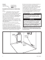
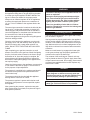
A confined space may be ventilated in two ways:
A. Open up or provide at least two ventilating grilles to
an adjoining unconfined space. (Fig. 2)
Each of the two grilles must provide an opening of at
least 50 square inches, with all opening dimensions be-
ing at least 3”. One grille must be within 12” of the ceil-
ing; the other within 12” of the floor. (If the total exceeds
100,000 BTU/hour, additional grilles will be needed.)
B. Vent the room directly to the outdoors. (Provide one
square inch of opening for each 4,000 BTU/hr.)
For further information on ventilation guidelines and siz-
ing specifications, follow the National Fuel Gas Code/
NFPA 54/ANSI Z223.1/NFPA 54, Section 5.3.
If the total BTU/hour used by the appliances is less than
the maximum BTU/hr the space can support, the room
meets the Unconfined Space criteria and no further
ventilation is needed.
WARNING: Before installing the gas log set in a solid-
fuel burning fireplace, the chimney flue and firebox must
be cleaned of soot, creosote, and loose paint by a quali-
fied chimney cleaner.
WARNING
This heater shall not be installed in a confined
space or unusually tight construction unless
provisions are made for adequate combustion
and ventilation air.
WARNING
If the area in which the heater may be operated
is smaller than that defined as an unconfined
space, or if the building is of unusually tight
construction, provide adequate combustion and
ventilation air by one of the methods described
in the National Fuel Gas Code, ANSI Z223.1/
NFPA 54, 1992, Section 5.3, or applicable codes.
VO370-2
Ventilation
options
3/26/99 djt
Fig. 2 Ventilation options for confined spaces.
OPTION 1 -
Vents to Ad-
joining Rooms
OPTION 2 -
Remove Door
to Adjoining
Room
OPTION 3 -
Vents to Ad-
joining Rooms
12”
12”
VO370-2
Example:
Gas Range 55,000 BTU/hour
Vent-Free LogSet +25,000 BTU/hour
Total 80,000 BTU/hour

7
UVLC Series
Preparing the Fireplace
Gas Line Preparation
Before connecting the appliance, turn off all gas appli-
ances. Close the main gas valve at the gas meter or
appliances. Close the main gas valve at the gas meter
or LP tank. Make certain there is good ventilation where
the installation will be made. Installation should comply
with all applicable building codes and ANSI Z223.1/
NFPA 54, latest edition or CSA B-149.1. Use LP gas-re-
sistant pipe compound to seal threaded joints.
Installation to Existing Gas Line
There should be a manual ON/OFF valve within easy
reach of the appliance. If not, before installation of the
appliance, make certain a valve is installed. There may
be a second valve on the line close to the point where
the fireplace line branches off the main gas supply line.
During installation, make certain this valve is OFF.
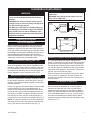
Manufactured Fireplace Preparation
Refer to the manufacturer’s fireplace installation manual
for the specific method of running the gas line into the
fireplace. The following method is typical of most manu-
factured fireplaces.
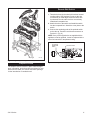
Insert a 1/2” gas pipe through the gas line tube provided
by the manufacturer, from outside the fireplace, as
marked by the manufacturer. An ON/OFF valve should
be placed within easy reach of the appliance. After the
gas supply is installed, reinstall the insulation removed
from the gas line tube, and pack it around the pipe, to
prevent cold air entry and to protect the gas line. (Fig. 3)
NOTE: The gas pipe should not come into contact with
any wood structure until it has reached a point at least
one (1) inch away from the fireplace side. (Fig. 3)
Masonry Fireplace Installation Preparation
A 1/2 inch gas supply line must be supplied to the
firebox. In most cases, this will require drilling a gas line
access hole through the masonry wall. The gas supply
line should then be sealed in the access hole with mor-
tar. The gas supply line should also have a valve within
easy reach of the appliance. Use only N.P.T. black iron
gas line. (Do not use cast-iron pipe).
Clean the fireplace and chimney (if used) of any ashes,
soot, creosote, or obstruction. This will minimize any
smell from the fireplace. We recommend cleaning by a
chimney sweep.
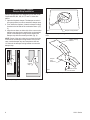
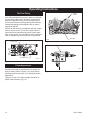
Flue Damper Preparation
The vented fireplace damper should be fully opened
when operating the appliance as a vented log set. A
damper stop clamp with set screw is provided as a
means to prevent full closure of the fireplace damper
blade. The clamp is designed to prevent accidental clo-
sure of the damper when in use. (Fig. 4) (If the damper
stop cannot be installed, the installer should install a
permanent damper stop that will keep the damper open
minimum of 1¹⁄₂”).
Do not allow fans to blow directly into the fire-
place. Avoid any drafts that alter burner flame
patterns.
WARNING: Do not use a blower insert, heat ex-
changer insert, or other accessory not approved
for use with this gas log set.
DO NOT burn solid fuels in a fireplace where an
unvented gas room heater or log set is installed.
Any outside air ducts and/or ashdumps in the
fireplace must be permanently closed at time of
appliance installation.
Do not install this appliance in bedrooms or
bathrooms.
WARNING: Any change to this heater or its con
-
trols can be dangerous.
WARNING:
Installation Instructions
760/Fplc Access. Ports
968/598UVL/UVHL
7/25/98
Fig. 3 Gas line installation - factory-built fireplaces.
Gas Access
Holes
Outside Air Access
Electrical
Access
Gas Supply
Line
Repack
Insulation
Ceramic
Knockout
Hole in
Outer
Casing
760
1”

8 UVLC Series
Manufactured Fireplace
Damper Stop Installation
Damper Stop #3030176 is designed for use with CFM
Corporation BR, BC, SR, SC,TF and TL Series fire-
places.
1. Open the fireplace damper. The damper must be in
the open position in order to attach the damper stop.
2. From inside the fireplace, locate the damper locking
bracket on the left side of the combustion dome. (Fig.
5)
3. Align the two slots on either side of the cutout on the
damper stop with the two small holes on the angled
portion of the damper locking bracket. Attach the
damper stop with the screws provided. (Fig. 6)
NOTE: Some of the early units may not have the holes
in the end of the damper locking bracket. If this is the
case, use the damper stop as a template to drill two
1/8” holes in the damper locking bracket to mount the
damper stop.
LS761/Damper Clamp Location
968/598 UVL/UVHL
7/27/98
Damper
Stop
Damper
Stop
761
Fig. 4 Damper stop placement.
LS855
Attach damper stop
11/99
Damper Locking
Bracket
Damper
Stop
#3030176
Attachment Screws
- Two Provided
LS855
Fig. 6 Attach the damper stop.
LS854
Locate damper
lock bracket
11/99
Damper Locking Bracket
LS854
Fig. 5 Locate the damper locking bracket inside the fireplace
dome.

9
UVLC Series
Burner Assembly Location
Centrally locate the unit in the fireplace, far enough
back into the firebox to accomplish adequate draft (if
use as a vented appliance is planned). Ensure the front
grate feet sit inside the front edge of the fireplace a
minimum of 3”. (Fig. 7b)
Clearances
To ensure the safe installation into a masonry or fac-
tory-built fireplace, carefully observe the following
instructions:
1. Sidewall Clearances: The clearance from the inside
of the front opening of the fireplace to any combustible
wall should not be less than 3¹⁄₂”. (Fig. 7a)
2. Ceiling Clearances: The ceiling height should not be
less than 42” from the top of the fireplace opening. (Fig.
7A)
3. Mantel Clearances:
When installing an ANSI Z21.11.2 ventless appliance,
the finishing material used for the mantel must be rated
at 250°F or greater. Refer to the firebox instructions for
any further information.
Without Hood: If no hood is installed, then there must
be noncombustible material from the top front opening
of the fireplace to a height of at least 20” and the full
width of the fireplace. A combustible flat mantel shelf
can be no closer than 38¹⁄₂” from the top of the fireplace
opening. (Fig. 7b)
With Hood: If a hood is installed there must be non-
combustible material from the top front opening of the
fireplace to a height of 7¹⁄₂” and the full width of the fire-
place. A combustible flat mantel shelf may be installed
according to the detail in Fig. 7c.
3A. Mantel Depth: A combustible mantel can be no
deeper than 8”, at 12” above the hood. (Figs. 7b, 7c)
4. Grate Clearance: The minimum clearance between
the front legs of the grate and the front edge of the fire-
place is 3”. (Fig. 7b)
MC656-2
clearances
3/26/99 djt
42”
3¹⁄₂”
Min.
Noncombustible
Facing Material
Ceiling
3¹⁄₂”
Min.
MC656-2
763 Fplc Clrnc Top View
UVL/UVHL
7/28/98
Top View
Mantel Trim
Finished Wall Mate
-
rial
Firebox
3¹⁄₂”
Noncombustible Facing
Material
3¹⁄₂”
763
Front View
7a
764 Fplc Clearance, Side View
UVL/UVHL
7/28/98
8”
38¹⁄₂”
20”
Standoff
Noncombustible
Material
Front Edge of
Grate
3”
4”
Without Hood
7b
765 Fplc w/ Hood, detail
UVL/UVHL
7/27/98
With Hood
7c
Flat Mantel
Shelf
8”
7¹⁄₂”
12’
4”
Standoff
Seal with
Noncombus-
tible Material
4”
Hood
764
765
Fig. 7 Mantel Clearances.

10 UVLC Series
Positioning the Logs
The logs must be positioned on the grate and locating
pins as shown in Figure 8.
Gas logs must be properly positioned or the appliance
will not function properly, and may result in soot accu-
mulation on the inside of the firebox and/or on the gas
logs. Make sure there is no flame impingement on the
logs which could result in excessive carbon monoxide
emissions.
Make sure each bottom log engages the locator pins
on the grate, and top logs are properly positioned in
notches on the tops of the lower logs.
The contents of the small bags of volcanic rock may
only be placed as shown in Figure 8. Apply loose mate-
rial per instructions manual. Do not apply extra material
or material not supplied with the heater. Replace only
with Part No. 57897.
Gas Line Connection
Check the gas type. Use only the gas type indicated on
the appliance rating plate. If the gas listed on the plate
is not the type of gas supplied, DO NOT INSTALL the
log set. Contact your dealer for the proper model.
Always use an external regulator for all LP applances,
to reduce the supply tank pressure to a maximum of
14” w.c. This is in addition to the regulator fitted to the
heater.
The normal gas connection is made at the left side (fac-
ing the unit). If a right-side connection is desired, the
connecting pipe may be directed under or behind the
rear of the appliance, to terminate at the left-hand side
for connection to the inlet of the appliance.
Connect the appliance to the gas line using fittings and
aluminum tubing provided.
Close the valve knob on the appliance, turn the main
gas supply valve ‘ON’ and carefully check all gas con-
nections for leaks, with a soapy water solution or a
sniffer. DO NOT TEST FOR LEAKS WITH AN OPEN
FLAME.
Upon completing your gas line connection, a small
amount of air will be in the gas lines. When first lighting
the pilot, it will take a few minutes for the lines to purge
themselves of air. Once the purging is complete, the
pilot and burner will light and operate as indicated in
this manual. Subsequent lightings of the appliance will
not require purging.
Check the inlet pressure to the appliance, to ensure that
it is as shown in the table on page 2. The minimum is
for the purpose of input adjustment.
The pressure is controlled by the regulator and should
be checked at the pressure test point located in the
control valve body.
The pressure should be checked with the appliance
burning and the control set on ‘HIGH’.
The pressure regulator is preset and locked to avoid
tampering. If the pressure is not as specified, replace
the regulator.
After measuring the pressure, replace the test point
plug. Ensure there are no leaks, then place the logs in
their specified positions.
WARNING
Connection directly to an unregulated LP tank can
cause an explosion.
During the initial purging and subsequent light-
ings, never allow the gas valve control knob to
remain depressed in the ‘Pilot’ position without
lighting the pilot with a match or piezo ignitor.
There is a possibility of odor fade in LP. Never
install an LP appliance or service line below grade
without a gas detector.
WARNING
Failure to position the parts in accordance with
these diagrams or failure to use only parts spe-
cifically approved for use with this appliance may
result in property damage or personal injury.
This appliance is equipped for (natural or pro-
pane) gas. Field conversion is not permitted.

11
UVLC Series
Fireplace Screen
The fireplace screen must be in place when the appli-
ance is operating, and unless other provisions for com-
bustion air are made, the screen must have openings
for the introduction of combustion air.
LG116
UVLC24 log placement
11/99
Fig. 8 Placing the logs on the grate assembly.
LG116
PILOT
ON
OFF
PILOT
ADJ
TH
T PT H
TP
L
O
H
I
1
2
3
HV110
Honeywell valve
w/GWSK wall switch
11/99
TP/TH Terminal
TH Terminal
To Optional
GWSK Wall
Switch
HV110
Fig. 9 Connecting a wall switch to the valve termnals.
Remote Wall Switch
(Optional Model GWSK)
1. Thread wire through the electrical knockout located
on either side of the fireplace. Do not cut the wire
or insulation on metal edges. Ensure that the wire
is protected. Run the other end to a conveniently
located wall receptacle box.
2. Attach the wire to the switch and install the switch
into the receptacle box. Attach the cover plate to the
switch.
3. Connect the remaining ends of the optional switch
to the valve at Terminal 3 and the tab connector on
Terminal 1. (Fig. 9)
NOTE: If any of the original wire as supplied with the
appliance must be replaced, it must be replaced with a
wire of at least a 60°C temperature rating.

12 UVLC Series
The First Firing
On completing the gas line connection, a small amount
of air will be trapped in the gas line. When you first light
the unit with the pilot light, it will take a few minutes to
purge the trapped air. Once you have purged the gas
line, the pilot and burner will light and operate normally.
Subsequent lightings of the appliance will not require
purging the gas line.
When lit for the first time, the appliance will emit a slight
odor for an hour or two. This is due to paint and lubri-
cants used in the manufacturing process curing under
heat. This is normal. You may wish to have the windows
open to dissipate any odors during the curing process.
Flame Appearance
To obtain proper operation, it is imperative that the pilot
and main burner flame characteristics are steady, not
lifting or floating. Refer to Figure 11 for proper burner
flame appearance and Figure 12 for proper pilot flame
appearance.
Typically, the top 1/8” of the thermopile should be en-
gulfed in the pilot flame. (Fig. 12)
P102
Honeywell pilot
flame
6/16/99 djt
Thermopile
P102
Fig. 12 Proper pilot flame appearance.
Operating Instructions
HV101a
Honeywell valve
UVL
3/18/99 djt
PILOT
ON
OFF
PILOT
ADJ
L
O
H
I
Fig. 10 Honeywell Valve.
Piezo Igniter
Regulator Knob
Control Knob
HV101a
LG116
log flames
11/99
Yellow
Flames
Fig. 12 Proper burner flame appearance.
Red glow
LG116

13
UVLC Series
3. Open control access panel.
4. Push in gas control knob slightly and turn clock-
wise to “OFF”. Do not force.
5. Close control access panel.
1. STOP! Read the safety information above.
2. Turn off all electrical power to the fireplace.
3. For MN/MP/TN/TP appliances ONLY, go on to
Step 4. For RN/RP appliances turn the On/Off
switch to “OFF” position or set thermostat to
lowest level.
4. Open control access panel.
5. Push in gas control knob slightly and turn
clockwise to “OFF”.
10. Push the control knob all the way in and hold.
Immediately light the pilot by repeatedly depress-
ing the piezo spark ignitor until a flame appears.
Continue to hold the control knob in for about one
(1) minute after the pilot is lit. Release knob and it
will pop back up. Pilot should remain lit. If it goes
out, repeat steps 5 through 8.
FOR YOUR SAFETY READ BEFORE LIGHTING
instructions.
• If you cannot reach your gas supplier, call
the Fire Department
C. Use only your hand to push in or turn the gas
control knob. Never use tools. If the knob will not
push in or turn by hand, do not try to repair it, call a
qualified service technician. Applying force or any
attempted repair may result in a fire or explosion.
D. Do not use this fireplace if any part has been under
water. Immediately call a qualified service techni-
cian to inspect the heater and to replace any part of
the control system and any gas control which has
been under water.
A. This heater has a pilot which must be lit manu
-
ally. When lighting the pilot follow these instruc-
tions exactly.
B. BEFORE LIGHTING smell all around the heater
area for gas. Be sure to smell next to the floor
because some gas is heavier than air and will
settle on the floor.
WHAT TO DO IF YOU SMELL GAS
• Do not try to light any fireplace
• Do not touch any electric switch
• Do not use any phone in your building
• Immediately call your gas supplier from a
neighbor’s phone. Follow the gas supplier’s
To Turn Off Gas To Heater
Lighting And Operating Instructions
1. Turn the On/Off switch to Off position or set the
thermostat to lowest setting.
2. Turn off all electric power to the fireplace if
service is to be performed.
Lighting Instructions
6. Wait five (5) minutes to clear out any gas. Then
smell for gas, including near the floor. If you
smell gas, STOP! Follow “B” in the safety infor-
mation above. If you do not smell gas, go to the
next step.
7. Remove glass door before lighting pilot. (See
Glass Frame Removal section).
8. Visibly locate pilot by the main burner.
9. Turn knob on gas control counterclockwise
to “PILOT”.
• If knob does not pop up when released, stop
and immediately call your service technician or
gas supplier.
• If after several tries, the pilot will not stay lit,
turn the gas control knob to “OFF” and call your
service technician or gas supplier.
11. Replace glass door.
12. Turn gas control knob to “ON” position.
13. For RN/RP appliances turn the On/Off switch to
“ON” position or set thermostat to desired setting.
14. Turn on all electrical power to the fireplace.
WARNING:If you do not follow these instructions exactly, a fire or explosion
may result causing property damage, personal injury or loss of life.
Euro SIT SIT NOVA
Honeywell
PILOT
ON
OFF
ON
P
I
L
O
T
O
F
F
O
F
F
HI
OFF
PILOT
LO
FP1067
lighting instruction
knobs
3/9/01 djt
3/8" - 1/2"
FP1068
Lighting instructions
Pilots

14 UVLC Series
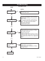
Troubleshooting
Honeywell Valve
• Supply line hooked up
• Shutoff valve open
• Lockout has engaged. Wait 60 seconds
and try again
• Piezo screws are tight for good ground
• For spark at electrode while depressing
piezo - 1/8” gap to pilot hood needed
• All wiring connections
• Replace piezo ignitor
• For air in the lines
• Thermopile needs a minimum of 325mV
• All wiring connections
• Replace thermopile
• Thermocouple needs a minimum of 14mV
• Defective valve. turn to pilot, meter should
read greater than 100mV. If not, replace the
valve.
• Valve turned on
• Wall switch is not turned on
• Thermopile needs a minimum of 325mV
• Plugged burner
Gas supply on
Pilot lights with Piezo
Pilot stays lit
Pilot lights main
burner
System OK
YES
YES
YES
YES
START
CHECK
NO
NO
NO
NO

15
UVLC Series
UVLC System Maintenance
The UVLC burner and control system consists of:
• Chassis
• Gas Orifice
• Grate assembly
• Six (6) decorative logs (UVLC18, UVLC24)
Seven (7) decorative logs (UVLC30)
• Gas valve assembly
The logs can get very hot. Handle them only when
they are cool.
Most of these components require only occasional
check-up and cleaning. Some may require adjustment.
If repair is needed, it should be performed by a qualified
technician.
In order to properly clean the burner and pilot assembly,
turn off the gas to the unit and remove the logs, expos
-
ing the burner and pilot assembly. Clean all foreign ma-
terials from the top of the burner. Check to make sure
that all burner parts are clean. Visually inspect the pilot.
Brush or blow away any dust or lint accumulations.
WARNING:
Failure to keep the primary air openings
of the burner clean may result in sooting and property
damage.
NOTE: The burner and pilot assembly should be
checked for any dust or lint at least every six months.
Replacement Parts
Contact the factory for questions about prices and poli-
cies covering replacement parts. Parts will be shipped
at prevailing prices. Normally, all parts can be ordered
through your Majestic distributor or dealer.
Refer to the parts illustration and listing on pages 16
and 17.
Maintenance and Safeguards
Keep the control compartment, logs and burner area
around the logs clean by vacuuming or brushing at least
twice a year.
THE LOGS CAN GET VERY HOT. HANDLE THEM
ONLY WHEN THEY ARE COOL.
Always turn off gas to the pilot before cleaning. For
relighting, refer to the lighting instructions.
The appliance and venting system (if used) should be
inspected before initial use, and at least annually by a
qualified field service person.
Always keep the appliance area clear and free from
combustible materials, gasoline, and other flammable
vapors and liquids.
Never obstruct the flow of combustion and ventilation
air. Keep the front of the appliance clear of all obstacles
and materials.
Leave clearance of at least 36” from the front of the
fireplace.
Although your gas logs are very realistic in appearance,
the fireplace must not be used for burning any solid
fuels.
To avoid irreparable damage to the appliance or per-
sonal injury, matches, paper, garbage, or any other
material must not be placed or thrown on top of the logs
or into the flames.
To avoid personal injury, do not touch hot surfaces
when the appliance is operating. Touch only the valve
control knob. Avoid contact with the grate feet or
prongs, or any other part which may be very hot.
Always ensure that the fireplace screen is closed when
the appliance is operating.
Any safety screen or guard removed for servicing the
appliances must be replaced before operating the appli-
ance.
Close supervision is necessary when the appliances is
being operated near children.
The appliance is intended for use as a gas heater
mounted in a vented or unvented fireplace as described
in the installation section of these instructions. It should
not be used for any other purpose.
Inspecting the Venting System
A vented fireplace venting system is designed and con-
structed to develop a positive flow adequate to remove
flue gasses to the outside atmosphere. See vented
fireplace installation instructions.
Any foreign objects in the venting system, except those
designed specifically for the venting system, may cause
spillage of the flue gases into the room. In extreme situ-
ations, carbon monoxide poisoning or suffocation may
occur.
Periodic examination and cleaning of the venting
system of the solid-fuel burning fireplace must be done
frequently by the home owner or a qualified agency.

16 UVLC Series
PILOT
ADJ
L
O
H
I
TPTH
TH
TP
Switch
(behind door)
15a/b
4
8
9
10
11
1a
1b
14
13
12
1e
24
5a
23a
23b
1g
1h
1d
1c
0333
UVLC parts
19a,b
2a,b
3
6
5b
7
16
17
22
1f
1
18
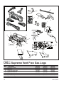
CFM Corporation reserves the right to make changes in design, materials, specifications, prices and discontinue colors and products at any time,
without notice.
UVLC Supreme Vent Free Gas Logs
1. Complete Log Set 20003423 20000327 20003428
1a. Back Log 20003425 7583198 20003430
1b. Log #V20 Cross Right 7583202 7583202 7583202
1c. Log #V19 Cross Left 7583199 7583199 7583199
1d. Front Log 20003424 7583197 n/a
1e. Left Middle Log 20003426 7583200 20003431
1f. Right Middle Log 20003427 7583201 20003432
Ref. Description UVLC18 UVLC24 UVLC30

17
UVLC Series
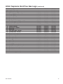
UVLC Supreme Vent Free Gas Logs (continued)
Ref. Description UVLC18 UVLC24 UVLC30
1g. Log #V43 Front Left n/a n/a 20004893
1h. Log #V44 Front Right n/a n/a 20004894
2a. Burner Supply w/Orifices - Natural 20003050 20000329 20000329
2b. Burner Supply w/Orifices - LP 20003687 20000318 20000318
3. 3/8” Flex Tubing 3304176 3304176 3304176
4. Volcanic Rock 20000198 20000198 20000198
5a. Damper Stop 3030176 3030176 3030176
5b. Damper Stop 4304045 4304045 4304045
6. Elbow Fitting 1/2” NPT (F) x 3/8” Flare 7523184 7523184 7523184
7. Lava Rock (Burner) 57897 57897 57897
8. Switch 1601597 1601597 1601597
9. Andiron Assembly 20005295 20005295 20005295
10. Swivel Door - Painted 20005340 20005345 20005345
11. Back Plate 20003023 20000321 20000321
12. Right Side Grate - Painted 20005338 20005338 20005338
13. Left Side Grate - Painted 20005339 20005339 20005339
14. Fettle - Painted 20005344 20005343 20005343
15a. Pilot Assembly - LP 55465 55465 55465
15b. Pilot Assembly - Natural 55464 55464 55464
16. Piezo Ignitor 20000062 20000062 20000062
17. Piezo Ignitor Cable 20000101 20000101 20000101
18. Ignitor Electrode Order Pilot Order Pilot Order Pilot
19a. Valve - LP 10000242 10000242 10000242
19b. Valve - Natural 10000235 10000235 10000235
20. ON/OFF Extension (Not shown) 20000007 20000007 20000007
21. HI/LO Extension (Not shown) 20000006 20000006 20000006
22. Pilot Bracket Assembly 20003530 20003530 20003530
23a. Pilot Shield 20003499 -- --
23b. Pilot Shield -- 20003500 20003500
24. Burner Housing Assembly 20003028 20000277 20000277

18 UVLC Series
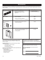
Accessories
The following accessories are available from your Majestic Fireplaces Dealer. If you need additional information beyond what your
dealer can supply, contact CFM Corporation, 2695 Meadowvale Blvd., Mississauga, Ontario, Canada L5N 8A3 Attention: Director of
Technical Service.
Accessory Description Model Number
Hood
Required to protect wall above
fireplace and/or mantel in certain
applications.
AH3244BK (BLACK)
AH3244PB (POLISHED BRASS)
Remote Control ON/OFF w/Batteries MRC1
ON/OFF Thermostat w/ Batteries MRC2
LCD ON/OFF Thermostat, Timer w/ Batteries MRC3
Remote Wall Switch Designed to provide remote on and off GWSK
control of burner flame
Fireback Cast Iron Construction. Designed to enhance CFB24M
flame effect with porcelain enamel
in ‘Midnight Black’.
AC110
Remote WAll Switch
5/7/99 djt
AC100
FIREPLA
CE HOOD
3/29/99 DJT
AC111
Fireback
from VErmont
5/7/99 djt
NOTE: If any of the original wire as supplied with
the appliance must be replaced, it must be re-
placed with a wire of at least a 105˚(C) temperature
rating.
Contact CFM Corporation with questions concerning
prices and policies covering replacement parts. Parts
may be ordered through your Majestic Fireplaces dis-
tributor or dealer.
You will need the following information when ordering
replacement parts:
• The appliance model number.
• The serial number.
• A description of the part.
Should you need additional information beyond what your
dealer can furnish, contact:
CFM Corporation
2695 Meadowvale Boulevard
Mississauga, Ontario
Canada L5N 8A3
Model and serial numbers are listed on the metal
rating plate attached to the burner assembly.
Record your model and serial numbers here to
ease future reference:
Model #
Serial #

19
UVLC Series
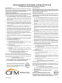
LIMITED WARRANTY & EXTENDED LIFETIME PROTECTION
For Majestic Fireplaces Gas Fireplace Products
BASIC WARRANTY:
CFM Corporation (hereinafter referred to collectively as the “Company”)
warrants that your new Majestic Fireplaces Gas Appliance is free from
manufacturing and material defects for a period of one year from date of
installation, subject to the following conditions and limitations.
EXTENDED LIFE TIME WARRANTY:
The heat exchanger, combustion chamber and ceramic burner parts of every
*CFM Corporation products are warranted for life to the original owner, subject
to proof of purchase and the following conditions and limitations:
1. This new Majestic Fireplaces product must be installed by a competent,
authorized service contractor. It must be installed and operated at all times in
accordance with the Installation and Operating instructions furnished with the
product. Any alteration, willful abuse, accident, or misuse of the product shall
nullify this warranty.
2. This warranty is non-transferrable, and is made to the original owner, provided
that the purchase was made through an authorized supplier of the Company.
3. This warranty is limited to the repair or replacement of part(s) found to be defective
in material or workmanship, provided that such part(s) have been subjected
to normal conditions of use and service, after said defect is confirmed by the
Company’s inspection.
4. The Company may, at its discretion, fully discharge all obligations with respect
to this warranty by refunding the wholesale price of the defective part(s).
5. Any installation, labour, construction, transportation, or other related costs/
expenses arising from defective part(s), repair, replacement, or otherwise of
same, will not be covered by this warranty, nor shall the Company assume
responsibility for same. Further, the Company will not be responsible for any
incidental, indirect, or consequential damages, except as provided by law.
6. All other warranties - expressed or implied - with respect to the product, its
components and accessories, or any obligations/liabilities on the part of the
Company are hereby expressly excluded.
7. The Company neither assumes, nor authorizes any third party to assume, on its
behalf, any other liabilities with respect to the sale of this Majestic Fireplaces
product.
8. The warranties as outlined within this document do not apply to chimney
components or other non Majestic Fireplaces accessories used in conjunction
with the installation of this product.
9. The Company will not be responsible for . . .
a) Down drafts or spillage caused by environmental conditions such as near-
by trees, buildings, roof tops, hills, or mountains.
b) Inadequate ventilation or negative air pressure caused by mechanical
systems such as furnaces, fans, clothes dryers, etc.
10. This warranty is void if:
a) The fireplace has been operated in atmospheres contaminated by chlorine,
fluorine or other damaging chemicals.
b) The fireplace is subjected to prolonged periods of dampness or
condensation.
c) Any damage to the fireplace, combustion chamber, heat exchanger or other
components due to water, or weather damage which is the result of, but
not limited to, improper chimney/venting installation.
d) Any alteration, willful abuse, accident, or misuse of the product.
GLASS DOORS & BRASS PLATED PARTS
Glass doors are not warranted for breakage due to misuse or accident.
Brass parts should be cleaned with lemon oil
only. Brass cleaners cannot be used.
Mortar mix and masonry cleaners may corrode the brass finish. The Company will
not be responsible for, nor will it warrant any brass parts which are damaged by
external chemicals or down draft conditions.
IF WARRANTY SERVICE IS NEEDED .
. .
1) Contact your supplier. Make sure you have your warranty, your sales receipt,
and the model/serial number of your Majestic Fireplaces product.
2) DO NOT ATTEMPT TO DO ANY SERVICE WORK YOURSELF.
GARANTIE DE BASE:
CFM Corporation (aux présentes nommée la “Société”) garantit votre nouveau
foyer au gaz Majestic Fireplaces contre tous défauts de fabrication et de
matières premières pour une période d’un an à compter de la date d’installation,
sujet aux conditions et limitations suivantes.
GARANTIE A VIE PROLONGEE:
Les pièces de l’échangeur de chaleur, de la chambre à combustion et du brûleur
en céramique de tout produit *CFM Corporation sont garanties pour la vie de
l’acheteur d’origine, le tout sujet à une preuve d’achat et aux conditions et
limitations suivantes:
1. Ce nouveau produit Majestic Fireplaces doit être installé par un entrepreneur
de service autorisé et compétent. Il doit être installé et utilisé en tout temps
selon les instructions d’installation et de fonctionnement fournies avec le produit.
Toute altération, abus volontaire, accident ou mauvais usage du produit annulera
cette garantie.
2. Cette garantie n’est pas transférable et est offerte à l’acheteur au détail d’origine,
à condition que l’achat soit effectué par l’entremise d’un détaillant autorisé de
la Société.
3. Cette garantie est limitée à la réparation ou au remplacement de(des) pièce(s)
trouvée(s) défectueuse(s) en matières premières ou main-d’oeuvre, à condition
que lesdites pièces aient été sujettes aux conditions normales d’usage et
de service, après que ledit défaut a été confirmé par une inspection par la
Société.
4. La Société peut, à sa discrétion, se décharger entièrement de toutes obligations
se rapportant à cette garantie en remboursant le prix de gros de la(des) pièce(s)
défectueuse(s).
5. Tous les frais/dépenses d’installation, de main-d’oeuvre, de construction, de
transport ou autres causés par une (des) pièce(s) défectueuse(s), une réparation,
un remplacement ou autre, ne seront pas couverts sous cette garantie, et la
Société n’assume aucune responsabilité pour ceux-ci. De plus, la Société ne
pourra être tenue responsable pour tous dommages fortuits ou indirects sauf
la ou prévu par la loi.
6. Toutes autres garanties, exprimées ou sous-entendues, en ce qui a trait au
produit, ses composants et accessiores, ou toutes obligations/responsabilités
de la part de la Société sont aux présentes expressment excluses.
7. La Société n’assume et n’autorise personne à assumer, en son nom, toutes
responsabilités en ce qui a trait à la vente de ce produit Majestic Fireplaces.
8. Les garanties, telles que décrites dans ce document, ne s’appliquent pas aux
compasants de cheminée ou aux autres accessoires non Majestic Fireplaces
utilisés conjointement pour l’installation de ce produit.
9. La Société n’encourrera aucune responsabilité pour . . .
a) Les refoulements de cheminées ou débordements causés par les conditions
environnementales comme par les arbres, les édifices, les toits, les côteaux
ou les montagnes adjacents.
b) Une ventilation inadéquate ou une pression d’air négative causée par
des systèmes mécaniques comme les fournaises, les ventilateurs, les
sécheuses, etc.
10. Cette garantie est nulle si:
a) Le foyer a été utilisé dans une atmosphère contaminée par du chlore, du
fluor ou tous autres produits chimiques.
b) Le foyer est assujetti à de longues périodes d’humidité ou de
condensation.
c) Des dommages sont causés au foyer, à la chambre de combustion. à
l’échangeur de chaleur ou aux autres composants par de l’eau ou par la
température qui est le résultat mais sans y être limité, d’une mauvaise
installation de cheminée/ventilation.
d) Toute altération, abus volontaire, accident ou mauvais usage du produit
annulera cette garantie.
PORTES EN VERRE & PIECES PLAQUEES LAITON
Les portes en verre ne sont pas garanties contre le bris causé par un mauvais
usage ou un accident.
Les pièces en laiton devraient être nettoyées qu’avec de l’essence de citron. Les
nettoyeurs de laiton ne peuvent pas être utilisés. La Société ne sera pas responsable
pour, et ne garantit pas les pièces en laiton qui sont endommagées par des conditions
chimiques externes ou de refoulement.
SI UN SERVICE SOUS GARANTIE EST REQUIS .
. .
1. Communiquez avec votre détaillant. Assurez-vous que vous avez votre garantie,
votre reçu de caisse ainsi que le numéro de modèle/série de votre produit
Majestic Fireplaces.
2. NE TENTEZ PAS D’EFFECTUER DES REPARATIONS
VOUS-MEME.
*Les foyers à gaz CFM Corporation portant ce scean
d’approbatic de la garantie spéciale sont couverts par
une garantie limitée à vie. Celle-ci inclue les brüleurs en
céramique Insta-Flame, le’échangeur de chaleur et la chambre
à combustion. Toutes les autres pièces sont couverte pour un an.
2695 Meadowvale Blvd.
Mississauga, ON L5N 8A3
*CFM Corporation products bearing this special Warranty
Seal of Approval carry a comprehensive Limited Lifetime
Warranty. This includes the Insta-Flame Ceramic Burners,
Heat Exchange System and Combustion Chamber. All
other parts are covered for one year.

© CFM Corporation
2695 Meadowvale Blvd. • Mississauga, Ontario, Canada L5N 8A3
800-668-5323 • www.cfmcorp.com
CFM Corporation
-
 1
1
-
 2
2
-
 3
3
-
 4
4
-
 5
5
-
 6
6
-
 7
7
-
 8
8
-
 9
9
-
 10
10
-
 11
11
-
 12
12
-
 13
13
-
 14
14
-
 15
15
-
 16
16
-
 17
17
-
 18
18
-
 19
19
-
 20
20


Majestic fireplaces Woodland UVLC30RP Installation And Operating Instructions Manual
- Taper
- Installation And Operating Instructions Manual
- Ce manuel convient également à
dans d''autres langues
Autres documents
-
Danby DDEF03813BD13 Le manuel du propriétaire
-
-
-
Danby DDEF02213BD13 Le manuel du propriétaire
-
FIELD CONTROLS GVD-4 thru -12 Gas Vent Damper Guide d'installation
-
CFM CVR Series Homeowner's Manual
-
Desa GCN6 Manuel utilisateur
-
Vermont Castings Stardance SNV30RP Manuel utilisateur
-
Allen + Roth 2416658 Manuel utilisateur
-
 GreenTouch 2416662 Guide d'installation
