Haier AS07BS4HRA Operation Manual And Installation Manual
- Catégorie
- Climatiseurs split-system
- Taper
- Operation Manual And Installation Manual
Ce manuel convient également à

AS07NS3HRA
AS09NS3HRA
AS12NS3HRA
AS15NS3HRA
AS18NS3HRA
AS24NS3HRA
AS07BS4HRA
AS09BS4HRA
AS12BS4HRA
AS15BS4HRA
AS18BS4HRA
AS24BS4HRA
SPLIT TYPE ROOM AIR CONDITIONER
OPERATION MANUAL AND INDOOR INSTALLATION MANUAL
Haier WiFi APP
Keep this operation manual for future reference.
͓6lease read this operation manual before using the air
conditioner.
Contents
PARTS AND FUNCTIONS......................................4
OPERATION.........................................................5
INDOOR UNIT INSTALLATION...............................8
MAINTENANCE..............................................
.....11
W
ARNING AND CAUTIONS....................................1
English
Table des matières
PIÈCES ET FONCTIONS.......................................15
FONCTIONNEMENT.............................................16
INSTALLATION DE L’UNITE INTÉRIEURE..............19
ENTRETIEN.........................................................22
AVERTISSEMENT ET MISES EN GARDE...............12
Français
PRECAUZIONI E AVVERTENZE…………….............23
PARTI E FUNZIONI…………………………................26
FUNZIONAMENTO………………………….............…27
INSTALLAZIONE DELL'UNITÀ INTERNA….............30
MANUTENZIONE……………………………...............33
Indice
Italiano
ADVERTENCIAY PRECAUCIONES.......................34
COMPONENTES Y FUNCIONES............................37
FUNCIONAMIENTO..............................................38
INSTALACIÓN DE UNIDAD INTERIOR...................41
MANTENIMIENTO................................................44
Contenido
Español
WARNUNG UND VORSICHT..................................45
TEILE UND FUNKTIONEN.....................................48
BEDIENUNG........................................................49
INNENEINHEIT INSTALLATION.............................52
PFLEGE...............................................................55
Inhalt
Deutsch
ĝRODKI OSTROĩNOĝCI ......................................56
CZĉĝCI I FUNKCJE...............................................59
DZIAàANIE...........................................................60
MONTAĩ-EDNOSTKI WEWNĉTRZNEJ..................63
KONSERWACJA URZĄDZENIA..............................66
ZawartoĞü
Polski
UYARI VE DøKKAT.................................................67
PARÇALAR VE FONKSøYONLAR...........................70
Operasyon……………………………….....................71
øÇ MEKAN ÜNøTESø.URULUMU...........................74
BAKIM.................................................................77
øçindekiler
Türkçe
ȆȇȅĭȊȁǹȄǼǿȈ………………………………………….78
ȂǼȇǾȀǹǿȁǼǿȉȅȊȇīǿǼȈ……………………………...81
ȁǼǿȉȅȊȇīǿǹ……………………………………………..82
ǼīȀǹȉǹȈȉǹȈǾǼȈȍȉǼȇǿȀǾȈȂȅȃǹǻǹȈ…......…..85
ȈȊȃȉǾȇǾȈǾ………………………………………..…..88
ȆİȡȚİȤȩȝİȞĮ
ǹȖȖȜȚțȐ
Sadråaj
UPOZORENJA I MJERE OPREZA……….................89
DIJELOVI I FUNKCIJE………………………..............92
RAD UREĈAJA……………………………..................93
INSTALACIJA UNUTARNJE JEDINICE…................96
ODRäAVANJE………………………………................99
Hrvatski
Conteúdos
AVISO E CAUÇÕES............................................100
PARTES E FUNÇÕES.........................................103
OPERAÇÃO.......................................................104
INSTALAÇÃO DE UNIDADE INTERIOR................107
MANUTENÇÃO..................................................110
Português
ɋɴɞɴɪɠɚɧɢɟ
ɉɊȿȾɍɉɊȿɀȾȿɇɂəɂɉɊȿȾɉȺɁɇɂɆȿɊɄɂ.......111
ɑȺɋɌɂɂɎɍɇɄɐɂɂ............................................114
ȿɄɋɉɅɈȺɌȺɐɂə................................................115
ɆɈɇɌȺɀɇȺȼɔɌɊȿɒȿɇɆɈȾɍɅ.......................118
ɉɈȾȾɊɔɀɄȺ.....................................................121
Ȼɴɥɝɚɪɫɤɢ
0010580714


WARNING:
·
If the supply cord is damaged, it must be replaced by the manufacturer,its service agent or
similarly qualified persons in order to avoid a hazard.
·
This appliance can be used by children aged 8 years and above and persons with reduced
physical, sensory or mental capabilities or lack of experience and knowledge if they have
been given superivision or instruction concering use of the appliance in a safe way and
understand the hazards involved. Children shall not play with the appliance. Cleaning and
·
The wiring method should be in line with the local wiring standard.
user maintenance shall not be made by children without supervision.
·
The type of connecting wire is H07RN-F.
All the cables shall have got the European authentication certificate. During installation, when the
·
connecting cables break off, it must be assured that the grouding wire is the last one to be broken off.
The breaker of the air conditioner should be all-pole switch; and the distance between its two contacts
should not be no less than 3mm. Such means for disconnection must be incorporated in the wiring.
·
·
Make sure installation is done according to local wiring regulation by professional persons.
·
·
A leakage breaker must be installed.
Make sure ground connection is correct and reliable.
Cautions
3. If the fuse of indoor unit on PC board is
it with the type of
T. 3.15A/ 250V
outdoor
broken,change it with the type of
T.25A/250V
The refrigerating circuit is leak-proof.
1.Applicable ambient temperature range:
Specifications
The machine is adaptive in following
situation
The power plug and connecting cable
acquired the local
2. If the power supply cord is damaged, it
must be replaced
manufacturer
qualified
person.
4. The wiring method should be in line with
the local wiring
5. After installation, the power plug should
be easily reached.
6. The waste battery should be disposed
properly.
7. Please employ the proper power plug,
cord.
9.In order to protect the units,please turn
10.Please check the installation instruction of WiFi in the WiFi module
30 seconds
later, cutting off the power.
8.
Cooling
Indoor
Maximum:D.B/W.B
Maximum:D.B/W.B
D.B
Maximum:D.B
D.B
Minimum:D.B/W.B
Maximum:D.B/W.B
Minimum:D.B/W.B
Outdoor
Indoor
Outdoor
Heating
32
o
C/23
o
C
24
o
C/18
o
C
o
C/-8
o
C
43
o
C/26
o
C
18
o
C
27
o
C
21
o
C/15
o
C
Outdoor
Maximum:D.B/W.B
Minimum:D.B
24
o
C/18
o
C
-15
o
C
(INVERTER)
o
C
7
-
Minimum:
Minimum:
or its service agent or a similar
broken,please
. If the fuse of
standard.
which fit into the
must have
off the A/C first,
by the
change
unit is
p
ower supply
attestation.
and at least
15
Do not obstruct or cover the ventilation
conditoner.Do not put fingers
inlet/outlet and
swing louver.
This appliance is not intended for use by persons (including children)
with reduced physiced, sensory or mental capabilities or lack of
experience and knowledge, unless they have been given supervision
or instruction concerning use of appliance by person responsible for
their safety. Children should be supervised to ensure that they do not
play with the appliance.
grille of the air
or any other things into the
1

the power supply cord
and so on.
2.Do not install in the place where there is any
possibility of inflammable gas leakage around the unit.
3.Do not get the unit exposed
to vapor or oil steam.
Cautions
Please call Sales/Service Shop for the Installation.
Do not attempt to install the air conditioner by yourself because improper works
may cause electric shock, fire, water leakage.
Connect the earth
cable.
earthing
WARNING
When abnormality such as burnt-small found,
immediately stop the operation button and
contact sales shop.
OFF
Use an exclusive
power source
with a circuit
breaker
ENFORCEMENT
Connect power supply cord
to the outlet completely
Use the proper voltage
Do not use power supply
cord in a bundle.
Take care not to damage
the power supply cord.
1.Do not use power supply cord extended
or connected in halfway
STRICT
ENFORCEMENT
STRICT
STRICT
ENFORCEMENT
PROHIBITION
PROHIBITION
PROHIBITION
PROHIBITION
Do not start or stop the
operation by disconnecting
Do not channel the air flow directly
at people, especially at infants or
the aged.
Do not try to repair or
reconstruct by yourself.
Do not use for the purpose of storage of
food, art work, precise equipment,
breeding, or cultivation.
CAUTION
Take fresh air occasionally especially
when gas appliance is running at the
same time.
PROHIBITION
STRICT
ENFORCEMENT
Do not operate the switch with
wet hand.
PROHIBITION
PROHIBITION
PROHIBITION
PROHIBITION
PROHIBITION
Do not install the unit near a fireplace
or other heating apparatus.
Check good condition of the
installation stand
Do not pour water onto the unit
for cleaning
PROHIBITION
Do not place animals or plants in
the direct path of the air flow
Do not place any objects on or
climb on the unit.
Do not place flower vase or water
containers on the top of the unit.
Do not insert objects into the air
inlet or outlet.
PROHIBITION
PROHIBITION
PROHIBITION
STRICT
ENFORCEMENT
Check proper
installation of the
drainage securely
WARNING
2

Trouble shooting
Before asking for service, check the following first.
Normal
Performance
inspection
Noise is heard
Phenomenon
Cause or check points
The system does not restart
immediately.
Smells are generated.
Mist or steam are blown out.
Multiple
check
Poor cooling
When unit is stopped, it won't restart
elapsed to protect the system.
When the electric plug is pulled out
and reinserted, the protection circuit
During unit operation or at stop,
a swishing or gurgling noise may
(This noise is generated by
refrigerant flowing in the system.)
During unit operation, a cracking
noise may be heard.This noise is
temperature changes.
Should there be a big noise from
filter may be too dirty.
This is because the system
circulates smells from the interior
During COOL or DRY operation,
This is due to the sudden cooling
Is power plug inserted?
Is there a power failure?
Is fuse blownout?
Is the air filter dirty?
Are there any obstacles before
Is temperature set correctly?
Are there some doors or
Is there any direct sunlight
through the window during the
Are there too much heat sources
or too many people in the room
In dry mode,
fan
speed can’t be changed.
In DRY mode, when room
than temp.setting+2
o
C,unit will
regardless of FAN setting.
during cooling operation?
cooling operation?(Use curtain)
windows left open?
inlet and outlet?
Normally it should be cleaned
every 15 days.
run intermittently at LOW speed
temperature becomeslower
indoor unit may blow out mist.
of indoor air.
air such as the smell of furniture,
paint, cigarettes.
air flow in unit operation, air
generated by the casing expanding
or shrinking because of
be heard.At first 2-3 minutes after
unit start, this noise is more noticeable.
will work for 3 minutes to protect the
air conditioner.
immediately until 3 minutes have
Trouble shooting
EUROPEAN REGULATIONS
CONFORMITY FOR THE MODELS
1
1+2=
kg
R410A
2
kg
2=
1=
B
C
D
FE
kg
A
This product contains fluorinated greenhouse gases covered by
the Kyoto Protocol. Do not vent into the atmosphere.
Refrigerant type:R410A
GWP* value:1975
GWP=global warming potential
Please fill in with indelible ink,
WKHIDFWRU\UHIULJHUDQWFKDUJHRIWKHSURGXFW
WKHDGGLWLRQDOUHIULJHUDQWDPRXQWFKDUJHGLQWKHILHOG and
WKHWRWDOUHIULJHUDQWFKDUJH
on the refrigerant charge label supplied with the product.
The filled out label must be adhered in the proximity of the product
charging port (e.g. onto the inside of the stop value cover).
A contains fluorinated greenhouse gases covered by the Kyoto
Protocol
B factory refrigerant charge of the product: see unit name plate
C additional refrigerant amount charged in the field
D total refrigerant charge
E outdoor unit
F refrigerant cylinder and manifold for charging
IMPORTANT INFORMATION REGA-
RDING THE REFRIGERANT USED
Contains fluorinated greenhouse gases
covered by the Kyoto Protocol
CE
All the products are in conformity with the following
European provision:
- Low Voltage Directive 2006/95/EC
- Electomagnetic Compatibility 2004/108/EC
ROHS
The products are fulfilled with the requirements in the
directive 2011/65/EU of the European parliament and of
council on the Restriction of the use of Certain Hazardous
Substances in Electrical and Electronic Equipment (EU
RoHS Directive)
WEEE
DISPOSAL REQUIREMENTS:
Your air conditioning product is marked with this
symbol.This means that electrical and electronic
products shall not be mixed with unsorted
household waste. Do not try to dismantle the
system yourself : the dismantling of the air
In accordance with the directive 2012/19/EU of the European
parliament, herewith we inform the consumer about the dis-
posal requirements of the electrical and electronic products.
conditioning system,treatment of the refrigerant, of oil and of
other part must be done by a qualified installer in
accordance
with relevant local and national legislation. Air conditioners
must be treated at a specialized treatment facility for reuse,
recycling and recovery. By ensuring this product is disposed
of correctly, you will help to prevent potential negative cons-
equences for the environment and human health. Please
contact the installer or local authority for more information.
Battery must be removed from the remote controller and dis-
posed of separately in accordance with relevant local and
nationl legislation.
Voltage:230V
Climate:T1
3

Parts and Functions
Remote controller
Indoor Unit
Outdoor Unit
4
OUTLET
INLET
CONNECTING PIPING
AND ELECTRICAL WIRING
DRAIN HOSE
4
Display board
Actual inlet grille may vary from the one shown in the
manual according to the product purchased
(adjust left and
ow)
Vertical blade
r
ight air fl
Air Purifying Filter
Inlet
(inside)
Emergency
Switch
Horizontal flap
(adjust up and down air flow
Don't adjust it manually)
Outlet
Inlet grille
6
5
2
1
4
3
6
4
2
1
5
3
(inside)
7
8
Anion generator
Display board
1
4
2
3
1
5
Operation mode indicator
(lights up when the compressor is on.)
Timer mode indicator
(Lights up whenTimer operation is selected.)
Power indicator
(Lights up when unit starts.)
Ambient temp display
When receiving the remote control signal, display the set temperature.
Remote signal receiver
(A beeping sound is generated when a signal from remote controller isreceived.)
2 3 4 5
10.
12.
SWING UP/DOWN button
13.
15. SLEEP button
14. HEALTH button
16.
18. Auto button
19. POWER ON/OFF button
21. TEMP button
22.
TIMER OFF/ON
23.
1. Mode display
Operation mode
AUTO
FAN
COOL DRY
Remote controller
2. Signal sending display
4.FAN SPEED display
5. LOCK display
6. TIMER OFF display
TIMER ON display
7. TEMP display
3. SWING display
LO MED HI
AUTO
Display
circulated
8.
Additional functions display
Operation mode
Remote controller
QUIET
TURBO
SLEEP
Supplemented
electrical
heating
HEALTH
9. TURBO/Quiet button
HEAT button
11. COOL button
FAN SPEED button
LOCK
button
Control the lightening and extinguishing
of the indoor LED display board.
17. LIGHT button
20. DRY button
button
SWING LEFT/RIGHT
button
24. EXTRA FUNCTION button
25.CANCEL/CONFIRM button
Function: Setting and cancel to the
timer and other additional functions.
26. RESET button
When the remote controller appears
abnormal, use a sharp pointed
article to press this button to reset
the remote.
Healthy function is not available for some units.
Function:
FAN Healthy airflow
Fahrenheit/Celsius mode conversion
1
2
3
24
23
25
26
20
21
22
19
18
5
8
7
6
4
15
16
9
10
11
12
13
14
17
Turbo/Quiet Auto
Cool Heat Dry
Health
Sleep
Lock
Timer On
Timer off
Light
Extra function
Confirm Cancle
Low-Temperature Heating Operation Down to 10
Fresh air A-B yard
4

Operation
Air Flow Direction Adjustment
Base Operation
Remote controller
Emergency operation and test operation
Emergency Operation:
Use this operation only when the remote controller is defective
or lost, and with function of emergency running, air conditoner
can run automatically for a while.
When the emergency operation switch is pressed, the " Pi "
sound is heard once, which means the start of this operation.
When power switch is turning on for the first time and
emergency operation starts, the unit will run automatically in
the following modes:
It is impossible to change the settings of temp. and fan speed,It
is also not possible to operate in timer or dry mode.
Pi
1.
temperature is below 16
o
C, do not use it in the
Test operation:
Use this switch in the test operation when the room
normal operation.
your finger from the switch: the cooling
Continue to press the test operation
switch for more than 5 seconds. After
you hear the "Pi" sound twice,
release
Test operation switch is the same as emergency switch.
operation starts with the air flow speed "Hi".
Under this operation mode,the fan motor of indoor
unit will run in high speed.
Pi Pi
Room
temperature
Designated
temperature
Timer
mode
Fan
speed
Operation
mode
Above 23
o
C 26
o
C AUTO COOL
No
When restart after remote turning off, the remote controller
When adjusting the flap by hand,turn off the unit.
When humidity is high,condensate water might occur
It is advisable not to keep horizontal flap at downward
position for a long time in COOLor DRY
otherwise, condensate water might occur.
adjusted to left or at air outlet if all vertical louvers are right.
mode ,
controller will automatically memorize the previous set swing position.
Note:
1.Status display of air flow
2.Left and right air flow adjustment
Pos.1
Pos.2
Pos.3
Pos.4
Pos.5
Pos.6
For each press of button, remote controller
displays as follows :
remote controller:
For each press of button, remote controller
displays as follows :
remote controller:
Cautions:
Remote controller:
Press
button
Every time the button is pressed, temp.setting
increase 1
o
C,if kept depressed, it will increase
rapidly
Every time the button is pressed, temp.setting
decrease 1
o
C,if kept depressed, it will
decrease rapidly
Select a desired temperature.
3.Fan function
2.Select temp.setting
Air conditioner is running under displayed fan speed.
When FAN is set to AUTO, the air conditioner
automatically adjusts the fan speed according to room
temperature.
Unit start
Press ON/OFF on the remote controller, unit starts.
changes as follows:
LOW
MED HI
Display
circulated
For each press button fan speed
In HEAT mode,warm air will blow out after a short
periodof the time due to cold-draft prevention function.
When FAN is set to AUTO, the air conditioner automatically
adjusts the fan speed according to room temperature.
Cooling only unit do not have displays and functions
related with heating
Remote
Controller
Note
COOL
DRY
HEAT
FAN
In DRY mode, when room temperature becomes
lower than temp.setting+2
o
C,unit will run intermittently
at LOW speed regardless of FAN setting.
Under the mode of auto operation, air conditioner will
automatically select Cool or Heat operation according
to room temperature.
air conditioner
automatically adjusts the fan speed
temperature.
When FAN is set to AUTO, the
according to room
In FAN operation mode, the unit will not operate in
COOL or HEAT mode but only in FAN mode ,AUTO is
not available in FAN mode.And temp.setting is disabled.
In FAN mode,SLEEP operation is not available.
Operation
Mode
AUTO
Press button to enter additional options, when
cycle display to , will flash. And then press
enter to FAN function.
SwingSwing
Temp+
Temp-
Health
Extra Function
Confirm/Cancel
Timer On
Timer Off
Sleep
Lock
Light
Reset
Turbo/Quiet Auto
Cool Heat Dry
Vertical flap
COOL/DRY:
HEAT:
Initial state
5

Comfortable SLEEP
Operation
3.In AUTO mode
corresponding sleep mode adapted to the
automatically selected operation mode.
4. In FAN mode
It has no SLEEP function.
sleeping function is set up,if user resets TIMER function, the
state of timing-on,if the two
modes are set up at the same
time,
either of their operation time is ended first,the unit will
stop automatically,and the other mode will be cancelled.
5. When quiet sleeping function is set to 8 hours the quiet
Note to the power failure resume:
Press the sleep button ten times in five seconds and enter
function after hearing four sounds.And press the sleep button
ten times within five seconds and leave this function after
hearing two sounds.
sleeping time can not be adjusted.When TIMER function is
2.In HEAT mode
1 hours after SLEEP mode starts, temp will become
2 C lower than temp.setting. After another 1 hours,
temp decrease by 2 C further. After more another
3 hours, temp.risesby 1 C further.The unit will run
for further 3 hours then stops.Temp. is lower than
temp. setting so that room temperature won't be too
high for your sleep.
O
O
SLEEP
operation starts
SLEEP
operation stops
1 hr
1 hr
3 hrs
3 hrs
Rises 1
O
C
Temp.setting
Unit stop
In HEAT mode
Decreases 2
O
C
Decreases 2
O
C
The unit operates in corresponding sleep mode
set,the quiet sleeping function can't be set up.After the
sleeping function will be cancelled; the machine will be in the
Operation Mode
1. In COOL,DRY mode
SLEEP operation starts SLEEP operation stops
Approx.6hrs
1 hr
Rises 1
O
C
Rises 1
O
C
Temp.setting
Unit stop
In COOL, DRY mode
1 hr
1 hours after SLEEP mode starts,temp.will become
higher than temp.setting.After another 1 hours,
temp.risesby 1 futher .The unit will run for further
6 hours then stops Temp. is higher than temp.setting
so that room temperature won’t be too low for your
sleep.
O
C
1
O
C
Press button , the remote controller will
show , and then achieve to the
sleep function.
Press again this button , the
sleep function will
be cancelled.
O
Note
When TIMER function is set, the sleeping function can’t be
set up .After the sleeping function is set up
,if user resets
TIMER function, the sleeping function will be cancelled; the
machine will be in the state of timing-on.
Power Failure Resume Function
If the unit is started for the first time, the compressor will not
start running unless 3 minutes have elapsed. When the power
resumes after power failure, the unit will run automatically,
and 3 minutes later the compressor starts running.
Healthy airflow Operation
1.Press to starting
Setting the comfort work conditions.
2.The setting of healthy airflow function
Note:
1.After setting the healthy airflow function, the position
grill is fixed.
3.In cooling and dry, using the air conditioner for a long
time under the high air humidity, condensate water may
occur at the grille .
Notice: Do not direct the flap by hand. Otherwise, the
grille will run incorrectly. If the grille is not run correctly, stop
for a minute and then start, adjusting by remote
controller.
2.In cooling, it is better to select the
mode.
3.The cancel of the healthy airflow function
Press button to enter additional options,Press this
button continuously, the louvers location will cycle between
in the following three locations, to choose the swing location
what you needed,and then press button to confirm.
Press button to enter additional options,Press this
button continuously, the louvers location will cycle between
in the following three locations again,and then press
button to cancel.
Healthy
airflow
upwarder
Healthy
airflow
downwarder
Present
position
SLEEP
SLEEP
6

Operation
Timer On/Off On-Off Operation
TURBO Operation
(This function is unavailable on some models.)
Press HEALTH button , the remote controller will show
and then achieve to the health function.
Press again this HEALTH button , the
health function will be
cancelled.
HEALTH Operation
(This function is unavailable on some models.)
a lot of anion effectively balance the quantity of position
up the dust sediment in the room and finally clean the
and anion in the air and also to kill bacteria and speed
air in the room.
The anion generator in the airconditioner can generate
1.After unit starts, select your desired operation mode.
2.Press / button to change TIMER mode.
Then select your desired TIMER mode (TIMER ON or
TIMER OFF ). " "or " "will flash.
3.Press / button to set time.
Hints:
After replacing batteries or a power failure happens, time
setting should be reset.
According to the Time setting sequence of TIMER ON or
Press the button for each time, setting time in the first
12 hours increased by 0.5 hour every time, after 12
hours,increased by 1 hour every time.
After adjust the time,press button and confirm the
time ON or OFF button will not flash any more.
4.Confirm timer setting
5.Cancel timer setting
TIMER OFF, either Start-Stop or Stop-Start can be
achieved.
TIME
OFF
TIME
ON
TIME
OFF
TIME
ON
Loading of the battery
1
2
3
4
Remove the battery cover;
Load the batteries as illustrated.
2 R-03 batteries, resetting key
(cylinder);
Be sure that the loading
is in line with th
e" + "/"-";
Load the battery,then put on the cover again.
The distance between the signal transmission head and the rece-
iver hole should be within 7m without any obstacle as well.
When electronic-started type fluorescent lamp or change- over
wireless telephone is installed in the
ver is apt to be disturbed in receiving
the signals,
so the distance to the indoor unit should be shorter.
type fluorescent lamp or
room, the recei
Note:
Full display or unclear display during operation indicates the
ries have been used up.
Please change batteries.
If the remote controller can't run normally during operation, please
reload several minutes later.
batte
remove the batteries and
Press button " 0.5 " will appear ,after 10 seconds
the time display will be blank.
TIME
ON
ON
Press button " 0.5 " will appear ,after 10 seconds
the time display will be blank.
TIME
OFF
OFF
Press the button the time display eliminated.
Press the
cancel
TURBO
QUIET
When you need fast cool or fast dehumidification,you
can choose the Turob function; when you sleep, read,
you can choose Quiet function
bu on, you can switch the “Turbo”
and “Quiet”
will swith as below
When running in Turbo the fan speed is the highest,
when running in Quiet, the fan speed is super slow
Turbo/Quiet Auto
Cool Heat Dry
2
Turbo/Quiet
7

Indoor Unit Installation
Driver
Torque wrench
(17mm,22mm,26mm)
Nipper
Reamer
Hacksaw
Pipe cutter
Gas leakage detector or
soap-and-water solution
Hole core drill
Flaring tool
Spanner(17,19 and 26mm)
Knife
Measuring tape
Necessary Tools for Installation
Power Source
Before inserting power
into receptacle, check the voltage without
fail.
The power
supply is the same as the
corresponding nameplate.
Install an exclusive branch circuit of the power.
A receptacle shall be set up in a distance where the power cable
can
be
reached.
Donotextendthecablebycuttingit.
Selection of Installation Place
Place, robust not causing vibration, where the body can be
supported sufficiently.
Place, not affected by heat or steam generated in the vicinity,
where inlet and outlet of the
unit are not disturbed.
Place, possible to drain easily, where piping can be conne-
cted with the outdoor unit.
Place, where cold air can be spread in a room entirely.
Place, nearby a power receptacle, with enough space around.
Place where the distance of more than lm from televisions,
radios, wireless apparatuses
a
nd fluorescent lamps can be
left.
In the case of fixing the remote controller on a wall, place
where the indoor unit can
receive signals when the fluore-
scent
lamps
in the room are lightened.
The distance between
theindoorunitandthe
floor should be more
than 2m.
ThemodelsadoptHFCfreerefrigerantR410A
more than
10cm
more than 15cm
more than 10cm
Arrangement of piping
directions
Rear left
Left
Rear
right
Right
Below
Attention must be paid to
the rising up of drain hose
Remote controller (1)
R-03 dry battery (2)
Mounting plate (1)
Drain hose (1)
Ø4X25 Screw
(4)
Plastic cap (4)
Accessory Parts
FOR 09K 12K
FOR 18K
FOR 24K
Selection of Pipe
Drawing for the installation of indoor units
Air purifying filter(Optional) (1)
Please be subject to the actual product purchased,the above picture is just for your reference.
8

Indoor Unit Installation
Fix to side bar and lintel a mounting bar, Which is separately sold, and
then
fasten the plate to the fixed mounting bar.
Refer to the previous article, “ When the mounting plate is
position of wall hole.
Make a hole of 70 mm in diameter, slightly descending to outside the wall
Install piping hole cover and seal it off with putty after installation
1. Carry out, based on the neighboring pillars or lintels, a
to be fixed against the wall, then temporarily fasten the plate
with
one steel nail.
2. Make sure once more the proper level of the plate, by
hanging a thread
with a
weight from the central top of the plate, then fasten securely the
plate with
the
attachment steel nail.
3. Find the wall hole location A using a measuring tape
When the mounting plate is fixed side bar and lintel
Fitting of the Mounting Plate and
Positioning of the wall Hole
Lid for right
piping
Lid for under piping pipe
Fix with adhesive tape
Lid for left piping
Indoor/outdoor electric cable and drain hose must be bound with
efrigerant
piping by protecting tape.
[ Other direction piping ]
Cut away, with a nipper, the lid for piping according to the piping
direction
and
then bend the pipe according to theposition of wall
hole. When bending, be
careful not to crash
pipes.
Connect beforehand the indoor/outdoor electric cable,
and then
pull out the
connected to the heat insulation of connecting part
specially.
proper leveling
for
the plate
first fixed “,
for the
Making a Hole on the Wall and Fitting the Piping Hole Cover
Drawing of pipe
Installation of the Indoor Unit
[ Rear piping ]
Draw pipes and the drain hose, then fasten them with the adhesive tape
[Left
Left-rear piping ]
In case of left side piping, cut away, with a nipper, the lid for left
piping.
In case of left-rear piping, bend the pipes according to the piping
direction to
the mark of hole for left-rear piping which is marked on
heat
insulation materials.
1. Insert the drain hose into the dent of heat insulation materials of
indoor
unit.
2. Insert the indoor/outdoor electric cable from backside of indoor
unit,
andpullit
out on the front side, then connect them.
3. Coat the flaring seal face with refrigerant oil and connect pipes.
Cover the connection part with heat insulation materials closely,
and
make sure
fixing with adhesive tape
Hangsurelytheunitbodyontotheupper
notches of the
mounting plate. Move the body
from
side to side to verify its
secure fixing.
In order to fix the body onto the mounting
plate,hold up
the body aslant from the
underside and
then put it down
perpendicularly.
R
emove terminal cover at rig
ht bottom corner of
indoor unit, then take
off wiring cover by removing
its screws.
mounting plate
When you unload the indoor unit,please use your hand to arise
slightly and lift the unit aslant until it leaves the mounting plate.
agraffe
mounting plate
the body to leave agraffe,then lift the bottom of the body outward
Heat insulation
material
Drain hose
Piping
Pipe supporting
plate
Indoor/outdoor electric cable
Indoor side
Outdoor side
Ø70mm
Wall hole
Thickness of wall
(Section of wall hole)
Piping hole pipe
G
When the mounting plate is first fixed
Fixing the indoor unit body
Unloading of indoor unit body
Connecting the indoor/outdoor Electric Cable
Removing the wiring cover
A=100mm
20mm
% ĭPP
30mm
% ĭPP
A=120mm
30mm
% ĭPP
A=113mm
18k
09/12/15k
24k
Pay attention to the following points before installation
of machine:
1.Take out cushion blocks on
the left and right angle beads
as shown in the following
Figure.
2. Remove 2 gaskets under the
cross-flow fan.
3. Clean the burr on the surface of fracture to avoid the power
wire from being scratched after removing the virtual opening
of the outgoing line slot on the case by hands in indoor
power-on process.
9

1. Insert from outside the room cable into left side of the wall
hole, in which the pipe has already existed.
2. Pull out the cable on the front side, and connect the cable
making a loop.
When connecting the cable, confirm the terminal number of indoor and
outdoor units carefully. If wiring is not correct, proper operation can not
becarriedoutandwillcausedefect.
Insertthecablefromtheback
side of the unit, then pull it out
on the front side.
Loosen the screws and insert
the cable ends fully into
terminal block, then
tighten the screws.
Pull the cable slightly to
make sure the cables have
been properly inserted and
tightened.
After the cable connection,
never fail to fasten the connected cable with the
wiring cover.
When connecting the cable after installing the indoor unit
When connecting the cable before installing the indoor unit
Note:
1. If the supply cord is damaged, it must be replaced by the manufacturer or its
service agent or a similar qualified person. The type of connecting wire is
H05RN-F
or H07RN-F.
2. If the fuse on PC board is broken please change it with the
type of
3.Thewiringmethodshouldbeinlinewiththelocalwiringstandard.
4. After installation, the power plug should be easily reached.
5. A breakershouldbeincorporatedintofixedwiring.Thebreakershouldbe
all-pole
switchandthedistancebetweenitstwocontactsshouldbenotless
than 3mm.
T.3.15A/250VAC (Indoor).
To Outdoor unit
Connecting wiring
4G0.75mm
2
Thepowersourcemustbeexclusivelyusedforair
conditioner.
In the case of installing an air conditioner in a moist place,
please install
an ea
For installation in other places, use a circuit breaker as far
as possible.
Pipecuttingiscarriedoutwith a pipecutterandbursmust beremoved.
After inserting the flare nut, flaring work is carried out.
Power Source Installation
Cutting and Flaring Work of Piping
Flare tool for R410A Conventional flare tool
Clutch-type clutch-type(Rigid-type) Wing-nut type (Imperial-type)
A 0~0.5mm 1.0~1.5mm 1.5~2.0mm
rth leakage breaker.
Lean
Damage of flare Partial Too outside
tcerrocnItcerroC
On Drainage
It becomes
high midway.
The gap with the
ground is too small.
Thereisthebad
smell from a ditch
It waves.
The end is imm-
ersed in water.
Pleaseinstallthedrainhosesoastobedownwardslopewithoutfail.
Please don’t do the drainage as shown below.
Please pour water in the drain pan of the indoor unit, and
is carried out surely to outdoor.
In case that the attached drain hose is in a room, please
apply heat
insulation
to
Less than
5cm
confirm that
drainage
it without fail.
Crack
Indoor unit
CheckItemsforTestRun
Gasleakfrompipeconnecting?
Heat insulation of pipe connecting?
Are the connecting wirings of indoor and outdoor firmly
Is the connecting wiring of indoor and outdoor firmly fixed?
Is drainage securely carried out?
Is the earth line securely connected?
Istheindoorunitsecurelyfixed?
Is power source voltage abided by the code?
Is there any noise?
Isthelampnormallylighting?
Arecoolingandheating(wheninheatpump)performednormally?
Is the operation of room temperature regulator normal?
Please kindly explain to our customers how to
operate
through the instruction manual.
inserted to the terminal block?
Put check mark
in boxes
Flare tooling die
1.Cut pipe
2.Remove burs
3.Insert the
are nut
4.Flare pipe
On Drainage
Check for Installation and Test Run
Code
indication
Trouble description
Analyze and diagnose
E1
E2
E4
E7
E14
Heat-exchange
sensor failure
Indoor EEPROM
error
Communication
fault between
indoor and outdoor
units
Indoor fan motor
malfunction
Operation halt due to breaking
of wire inside the fan motor;
Operation halt due to breaking
of the fan motor lead wires;
Detection error due to faulty
indoor unit PCB;
Indoor unit- outdoor unit signal
transmission error du
etowiring
error;
Faulty PCB;
Faulty EEPROM data;
Faulty EEPROM;
Faulty PCB;
Faulty connector connection;
Faulty thermistor;
Faulty PCB;
Room temperature
sensor failure
10

Maintenance
For Smart Use of The Air Conditioner
Setting of proper room
temperature
Close doors and windows
during operation
If the unit is not to be used
for a long time, turn off the
power supply main switch.
Use the timer effectively
Use the louvers effectively
Do not block the air inlet
or outlet
Proper
temperature
During cooling operation
prevent the penetration of
direct sunlight with
curtain or blind
OFF
Air Filter cleaning
Open the inlet grille by pulling it upward.
Remove the filter.
Clean the filter.
Attach the filter.
Close the inlet grille.
Push up the filter's center tab slightly until it is released
from the stopper, and remove the filter downward.
Use a vacuum cleaner to remove dust, or wash the filter with
water.After washing, dry the filter completely in the shade.
Attach the filter correctly so that the "FRONT" indication is
facing to the front.Make sure that the filter is completely
fixed behind the stopper.If the right and left filters are not
attached correctly, that may cause defects.
Remote Controller
Do not use the following for cleaning
Do not use water ,wipe the controller with a
dry cloth.Do not use glass cleaner or chemical
cloth.
Gasoline,benzine, thinner or cleanser may
damage the coating of the unit.
Hot water over 40
O
C(104
O
F) may cause
discoloring or deformation.
Wipe the air conditioner by using a soft and
dry cloth.For serious stains,use a neutral
detergent diluted with water.Wring the water
out of the cloth before wiping.then wipe off
the detergent completely.
Indoor Body
Once every
two weeks
1.Open the lnlet Grille
2.Detach the standard air filter
3.Attach Air Purifying Filter
4.Attach the standard air filter
(Necessary installation)
5.Close the Inlet Grille
Close the Grille surely
Slide the knob slightly upward to
release the filter, then withdraw it.
Put air purifying filter appliances into the
right and left filter frames.
Detach old Air Purifying Filter
NOTE:
The photocatalyst air purifying filter will be solarized in fixed
time. In normal family,
it will be solarized every 6 months.
Prop up the inlet grille by using a
small device named grille-support
ATTENTION:
The white side of the photocatalyst air purifying
filter face outside,
and the black side face the unit.
The green side of the bacteria-killing medium air
and the white side face the unit.
Please keep the bacteria-killing medium air purifying filter in
avoid long time directly sunshine
when you stop using it,or its ability of sterilization will
be
reduced.
The bacteria-killing medium air purifying filter will be used
for a long time,no need for replacement. But in the period
of using them ,you should remove the dust frequently by
Replacement of Air Purifying Filter
which located in the right side of
the indoor unit.
purifying filter face outside,
using vacuum cleaner or flaping them lightly,otherwise ,
its performance will be affected.
the cool and dry conditions
(NOTE: Air purifying filter is optional part)
11

AVERTISSEMENT:
Silecordond'alimentationestendommagé,ildoitêtreremplacéparlefabricant,sonagentdeserviceouun
technicienqualifiéafind'éviterundanger.
Cetappareilpeutêtreutilisépardesenf antsâgésde8ansetplusetdespersonneayantdescapacitésphysiques,
sensoriellesoumentalesréduites,
ouquimanquentd’expérienceetdeconnaissances,siellesontétésurveilléeset
forméesconcernantl’utilisationdel’appareilentoutsécuritéetcomprislesrisquesencourus.Lesenf antsnedoivent
pasjoueravecl'appareil.Lenettoyageetl’entretiendel'utilisateurnedoiventpasêtreeffectuéspardesenfantssans
surveillance.
Laméthodedecâblagedoitêtreconformeàlanormedecâblagelocale.
LetypedefilderaccordementestH07RNͲF.
Touslescâblesdoiventavoirobtenulecertificatd'authentificationeuropéenne.Lorsdel'installation,ilfauts'assurer
quelefildemasseestledernieràsedétacher
lorsquelescâblesderaccordementsedétachent.
Ledisjoncteurduclimatisateurdoitêtreomnipolaire,etladistanceentrelesdeuxcontactsnedoitpasêtreinférieureà
3mm.Detelsmoyensdecoupuredoiventêtreincorporésdanslecâblage.
S’assurerquel'installationsefaitconformémentàlaréglementationdecâblage
localepardesprofessionnels.
S’assurerquelaconnexionàlaterreestcorrecteetfiable.
Undisjoncteurdefuitedoitêtreinstallé.
MISESENGARDE
ƽ Nepasobstrueroucouvrirlagrilledeventilationdu
climatisateur.Nepasmettrelesdoigtsoutoutesautres
chosesdansl'entrée/lasortieetbalancerlevolet.
ƽ Cetappareiln'estpasdestinéàêtreutilisépardes
personnes(ycomprislesenfants)ayantdescapacités
physiques,sensoriellesoumentalesréduites,ouqui
manquentd’expérienceetdeconnaissances,àmoins
qu'ellessoientsurveilléesouforméesconcernant
l’utilisationdel’appareilparunepersonneresponsablede
leursécurité.Les
enfantsdoiventêtresurveilléspour
s'assurerqu'ilsnejouentpasavecl'appareil.
Caractéristiques
ƽ Lecircuitfrigorifiqueestétanche.
Lamachineestadaptéeàlasituationsuivante
1. Plagedetempératureambianteapplicable:
Intérieur Maximum:D.B/W.B 32°C/23°C
Minimum:D.B/W.B 21°C/15°C
Refroidissement
Extérieur Maximum:D.B/W.B 43°C/26°C Minimum:
D.B 18°C
Intérieur Maximum:D.B 27°C Minimum:D.B 15°C
Extérieur Maximum:D.B/W.B 24°C/18°C
Minimum:D.B/W.B -7°C/-8°C
Chauffage
Extérieur Maximum:D.B/W.B 24°C/18°C Minimum:D.B
-15°C
12
2. Si le cordon d'alimentation est endommagé, il doit être
remplacéparlefabricantousonagentdeserviceouparune
personnequalifiée.
3.Silefusibledel'unitéintérieuresurlacartePCestcassé,
veuillez le remplacer par le type de T.3.15A/250V. Si le
fusible de l'unité
extérieure est cassé, remplacezͲle par le
typedeT.25A/250V
4.Laméthodedecâblagedoitêtreconformeàlanormede
câblagelocale.
5. Après l'installation, la prise d'alimentation doit être
facilementaccessible.
6.Lapileuséedoiventêtreéliminéecorrectement.
7. Veuillez utiliser la prise d’alimentation appropriée, qui
s’emboîtedanslecordond’alimentation.
8.Laprised'alimentationetcâblederaccordementdoivent
avoiracquisl'attestationlocale.
9.Afindeprotégerlesunites,veuillezd’abordéteindreA/C,
etcouperl’alimentationaumoins30secondesplustard.
10.Veuillezvérifierlesinstructionsd'installationduWiFi
danslemoduleWiFi.

Misesengarde
Avertissement
Veuillezappelerlemagasindevente/servicepourl’installation.
Ne pas essayer d'installer le climatiseur vousͲmême, parce que les œuvres inadéquates peuvent provoquer un choc
électrique,unincendie,unefuited'eau.
Avertissement
APPLICATION
STRICTE
Misesengarde
Nepasutiliserdanslebutdestockagedela
nourriture,desoeuvresd'art,desinstruments
deprécision,d'élevage,oudeculture.
Prendrel'airfraisdetempsentemps,surtout
quand un appareil à gaz est en cours
d'exécutiondanslemêmetemps.
Ne pas faire fonctionner l'interrupteur avec
lesmainsmouillées.
Ne pas installer l'appareil près d'une
cheminéeoud'unautrechauffage.
Vérifierlebonétatdusupportd'installation
Ne pas verser d'eau sur l'unité pour le
nettoyage
Ne pas mettre des animaux ou des plantes
dansletrajetdirectdufluxd'air
Ne pas placer d'objets sur ou monter sur
l'unité.
Ne pas placer lavase oude récipients d'eau
enhautdel’unité.
13
Lorsqueuneanomaliecommeunpetitbrûléesttrouvée,
arrêter immédiatementle bouton defonctionnement et
contacterlemagasindevente.
Utiliserunesource
d’alimentationexclusive
avecundisjoncteurde
circuit
Vérifierl'installationcorrectedudrainageentoute
sécurité
Connecter complètement le cordon
d’alimentationàlasortie
Utiliserlabonnetension
1.Nepasutiliserlecordond'alimentationprolongéouconnecté
àmiͲchemin
2.Nepasinstallerdansl'endroitoùilyaunepossibilitédefuites
degazinflammableautourdel'unité.
3.Nepaslaisserl'appareilexposéàlavapeurouàla
vapeurd'huile.
Ne pas utiliser le cordon d'alimentation
dansunpaquet.
Prendre soin de ne pas
endommager le cordon
d'alimentation.
APPLICATION
STRICTE
APPLICAT
STRICTE
ION
INTERDICTION
Nepasinsérerd'objetsdansl'entréeoulasortied'air.
Ne pas démarrer ou arrêter le
fonctionnement en débranchant le
cordond'alimentationetainsidesuite.
Ne pas canaliser le flux d'air
directement aux personnes,
surtout aux enfants ou aux
personnesâgées.
Ne pas essayer de réparer
ou de reconstruire
vousͲmême.
INTERDICTION
INTERDICTION
INTERDICTION
Brancherlecâbledeterre.
Miseàla
terre
INTERDICTION
INTERDICTION
INTERDICTION
APPLICATION
STRICTE
INTERDICTION
INTERDICTION
INTERDICTION
INTERDICTION
INTERDICTION
INTERDICTION
INTERDICTION

Dépannage
Avantdedemanderunservice,vérifierd’abordlasuite.
Phénomène Causeoupointsdecontrôle
Le système ne
redémarre pas
immédiatement.
ƽLorsquel'unités'arrête,ellene
redémarrerapasimmédiatement
jusqu’àceque3minutessesont
écouléespourprotégerle
système.
ƽLorsquelapriseélectriqueest
tiréeetréinsérée,lecircuitde
protectionfonctionnerapendant
3minutespourprotégerle
climatiseur.
Un bruit est
entendu
ƽPendantlefonctionnementou
l'arrêtdel'unité,unbruitde
sifflementoudeglougloupeut
êtreentendu.Danslespremières
2Ͳ3minutesaprèsledémarrage
del'unité,cebruitestplus
perceptible(Cebruitestgénéré
parleréfrigérantcirculantdans
lesystème.)
ƽPendantlefonctionnementde
l'unité,unbruitdecraquement
peutêtreentendu.Cebruitest
généréparl'enveloppeen
expansionoucontractionen
raisondechangementsde
température.
ƽS’ilyaungrandbruitduflux
d’airdanslefonctionnementde
l’unité,lefltreàairpeutêtre
tropsale.
Les odeurs sont
générées.
ƽC'estparcequelesystème
circuledesodeursdel'air
intérieurtelsquel'odeurde
meubles,depeinture,de
cigarettes.
Le brouillard ou la
vapeur est soufflée
dehors.
ƽPendantlefonctionnement
REFROIDISSEMENTor
DESHUMIDIFICATION,l’untié
intérieurepeutsoufflerdehorsle
brouillard.Celaestdûau
refroidissementbrusquedel’air
intérieur.
Normale
inspectio
n de la
perform
ance
En mode
déshumidification,
lavitessedefanne
peut pas être
changée.
EnmodeDESHUMIDIFICATION,
lorsquelatempératureambiante
devientinférieureauréglagede
latempérature+2°C,l’unité
passeintermittenceBASSE
vitesseindépendammentde
réglageVENTILATEUR.
ƽEstͲcequelaprise
d’alimentationestinsérée?
ƽYaͲtͲilunepannedecourant?
EstͲcequelefusibleasauté?
Contrôle
multiple
Mauvais
refroidissement
ƽEstͲcequelefiltreàairest
sale?
ƽNormalement,ildoitêtre
nettoyétousles15jours.
ƽYaͲtͲildesobstaclesavantde
l’entréeetdelasortie?
ƽEscͲcequelatempératureest
correctementréglée?
ƽYaͲtͲildesportesoudes
fenêtreslaisséesouvertes?
ƽYaͲtͲillalumièredirectedu
soleilparlafenêtrependantle
fonctionnementde
refroidissement?(Utiliserle
rideau)
YaͲtͲiltropdesourcesde
chaleuroutropdegensdansla
sallependantlefonctionnement
derefroidissement?
14
CONFORMITEDELAREGLEMENTATION
EUROPEENNEPOURLESMODÈLES
Climat:T1Tension:230V
CE
Touslesproduitssontenconformitéaveclesdispositionseuropéennes
suivantes:
- DirectiverelativeauxBassesTensions2006/95/CE
CompatibilitéElectromagnetique2004/108/CE
ROHS
Lesproduitssontremplisaveclesexigencesdeladirective
2011/65/UEduParlementEuropéenetduConseilrelatifàlaLimitation
del'utilisationdeCertainesSubstancesDangereusesdans
l’EquipementElectriqueetElectronique(DirectiveRoHSdel'UE)
WEEE
Conformémentàladirective2012/19/UEduparlementEuropéen,
ciͲjoint,nousinformonsleconsommateursurlesexigencesrelativesà
l'éliminationdesproduitsélectriquesetélectroniques.
EXIGENCESRELATIVESÀL'ÉLIMINATION:
Votreproduitdeclimatisationestmarquéparce
symbole.Celasignifiequelesproduitsélectriqueset
électroniquesnedoiventpasêtremélangésavecles
déchetsménagersnontriés.Nepasessayerde
démonterl'appareilvousͲmême:ledémontagedu
systèmedeclimatisation,letraitementdu
réfrigérant,del'huileetd'autresparts
doiventêtre
faitsparuninstallateurqualifiéconformémentàlalégislationlocaleet
nationalepertinente.Lesclimatiseursdoiventêtretraitésdansun
centredetraitementspécialisépourlaréutilisation,lerecyclageetla
récupération.Ens'assurantqueceproduitestcorrectementéliminé,
vousaiderezàprévenirlesconséquencesnégativespotentielles
pour
l'environnementetlasantéhumaine.Veuillezcontacterl’installateur
oulesautoritéslocalespourplusd'informations.Lapiledoitêtre
retiréedelatélécommandeetséparémentéliminée,conformémentà
lalégislationlocaleetnationalepertinente.
INFORMATIONSIMPORTANTESCONCERNANTLE
REFRIGERANTUSE
Contient des gaz fluorés à effet de serre
c ouver ts par le Pr oto col e de Ky oto
Ceproduitcontientdesgazfluorésàeffetdeserrecouvertsparle
ProtocoledeKyoto.Nepasdévierdansl'atmosphère.
Typederéfrigérant:R410A
GWP*Valeur:1975
GWP=potentielderéchauffementplanétaire
Veuillezrempliravecdel'encreindélébile,
•1lachargederéfrigérantd'usineduproduit
•2laquantitéderéfrigérantsupplémentairechargéesurleterrainet
•1+2•lachargetotalederéfrigérantsurl'étiquettedechargede
réfrigérantfournieavecleproduit.
L'étiquetterempliedoitêtreapposéeàproximitédel'orificedecharge
deproduit(parexemple,surl'intérieurducouvercledela
valve
d'arrêt).
AcontientdesgazfluorésàeffetdeserrecouvertsparleProtocole
deKyoto
Bchargederéfrigérantd’usineduproduit:voirlaplaquedel’unité
Cquantitéderéfrigérantsupplémentairechargédansledomaine
Dchargederéfrigéranttotale
Eunitéextérieure
Fcylindrede
réfrigérantetcollecteurpourlechargement

Elémentsetfonctions
Ƶ Unitéintérieure
Panneaud'affichage
Récepteurdesignaldetélécommande
(Unbipestgénérélorsqu'unsignaldelatélécommandeestreçu.)
2Voyantd'alimentation(S'allumelorsquel'unitédémarre.)
3Voyantdemodedeminuterie
(S'allume lorsque le fonctionnement de la minuterie est
sélectionné.)
4 Voyant de mode de fonctionnement (s'allume lorsque le
compresseurest
enmarche.)
5Affichagedelatempératureambiante
Lors de la réception du signal de télécommande, afficher la
températuredeconsigne.
Selon le produit acheté, la grille d'admission peut être
différentedecelleprésentéedanscemanuel
ƵUnitéextérieure
1SORTIE
2ENTREE
3TUYAUDERACCORDEMENTETCABLAGEELECTRIQUE
4TUBEDEVIDAGE
Ƶ
Télécommande
1.Affichagedemode
2.Affichaged’émissiondesignal
3.AffichageBALAYAGE
4.AffichageVITESSEDU
VENTILATEUR
5.AffichageVERROUILLAGE
6.AffichageMINUTERIE
DESACTIVEE
AffichageMINUTERIEACTIVEE
7.AffichageTEMP
8.Affichagedesfonctions
supplémentaires
9.ToucheTURBO/SILENCIEUX
10.ToucheCHAUFFAGE
11.ToucheREFROIDISSEMENT
12.ToucheBALAYAGEHAUT/BAS
13.ToucheVITESSEDU
VENTILATEUR
14.ToucheAIRPUR
15.ToucheNOCTURNE
16.ToucheVERROUILLAGE
17.ToucheLUMIERE
controlerl'éclairageet
l'extinctiondupanneau
d'affichageàLEDsurl'unité
intérieure
18.ToucheAuto
19.ToucheMARCHE/ARRET
20.Touche
DESHUMIDIFICATION
21.ToucheTEMP
22.ToucheBALAYAGE
GAUCHE/DROITE
23.ToucheMINUTERIE
DESACTIVEE/ACTIVEE
24.ToucheEXTRAFONCTION
FoncƟon:VENTILATEURїFlux
d’airpurїConversiondemode
Fahrenheit/CelsiusїFoncƟonne
mentdechauffageàbasse
températurejusqu’à10°CїAir
fraisїAͲByard
25.Touche
ANNULER/CONFIRMER
Fonction:Réglageetannulation
del’heureet
desautres
fonctionssupplémentaires.
26.BoutonREINITIALISER
Lorsquelatélécommande
fonctionnedemanière
anormale,appuyezsurce
boutonàl'aided'uninstrument
àboutpointuafinderestaurerle
fonctionnementdela
télécommande.
LafonctionAIRPURn’estpasdisponiblesurcertainesunités.
15

FŽŶĐƟŽŶŶĞŵĞnt
FŽŶĐƟonnement de base
Télécommande
1. Démarrage de l’unité
Appuyer sur MARCHE/ARRET sur la télécommande, l’unité démarre.
2. ^ĠůĞĐƟŽŶ du réglage de la température
Appuyer sur la touche TEMP+/TEMP
TEMP+ Chaque fois que vous appuyez sur ceƩetouche,leréglagedela
température augmente de 1°C, le réglage est plus rapide en cas
d'appui prolongé
TEMP
Chaque fois que vous appuyez sur ceƩe touche, le réglage de la
température baisse de 1°C, le réglage est plus rapide en cas d'appui
prolongé
^ĠůĞĐƟŽŶŶĞƌ la température désirée.
3. FoncƟon VeŶƟlateur
Appuyer sur la touche EXTRA FONCTION pour entrer des ŽƉƟŽŶs
supplémentaires, lorsque le cycle Ăĸche , clignotera. Puis
appuyer sur CONFIRMER/ANNULER pour entrer dans la foncƟon
VENTILATEUR.
Chaque fois que vous appuyez sur la touche , la vitesse de
ǀĞŶƟlateur change comme suit:
Télécommande:
Le ĐůŝŵĂƟƐĂteur est en marche sous la vitesse du ǀĞŶƟlateur ĂĸĐŚée.
Quand le VENTILATEUR est réglé sur AUTO, le climĂƟƐĞur ajuste
automaƟƋƵĞment la vitesse du veŶƟlateur selon la température
ambiante.
Mode de
fŽŶĐƟŽŶŶĞŵĞn
t
Télécommande Remarque
AUTO
Dans le mode de fŽŶĐƟŽnnement
automĂƟque, le climaƟƐĞur ƐĠůĞĐƟŽnnera
automĂƟquement le mode
Refroidissement ou Chauīage selon la
température ambiante. Quand le
VENTILATEUR est réglésur AUTO, le
climĂƟseur ajuste automĂƟquement la
vitesse du venƟlateur selon la température
ambiante.
REFROIDISSEM
ENT
Les unités deƐƟnées au seul
refroidissement ne disposent pas de
foŶĐƟŽŶs et d'écrans liés au chauīage
DESHUMIDIFIC
ATION
En mode DESHUMIDIFICATION, lorsquela
température ambiante devient inférieure
au réglage de la température +2°C, l’unité
foŶĐƟŽŶŶĞra par intermiƩence à BASSE
vitesse indépendamment de réglage
VENTILATEUR
CHAUFFAGE
En mode CHAUFFAGE, l'air chaud souŋera
dehors après unecourte période de temps
à cause de la fŽŶĐƟon de prévenƟŽŶ
froid
projet.
VENTILATEUR
En mode de commande VENTILATEUR,
l’uniténefonĐƟonnera pas en mode
REFROIDISSEMENT ou CHAUFFAGE, mais
uniquement en mode VENTILATEUR, AUTO
n’est pas disponible en mode
VENTILATEUR. Et le réglage de la
température est déƐĂĐƟvé. Quand le
VENTILATEUR est réglé sur AUTO, le
climĂƟseur ajuste automĂƟquement la
vitesse du venƟlateur selon la température
ambiante. En mode VENTILATEUR, le mode
NOCTURNE n’est pas disponible.
16
FonĐƟonnement d'urgence et mode de test
FoŶĐƟŽŶŶĞŵĞnt d'urgĞŶĐĞ͗
ͻ hƟlisezcemodedefoŶĐƟonnement uniquement en cas de perte ou de défaillance de la
télécommande. Lorsque la foŶĐƟon d'urgence est en marche, le climaƟƐĞƵrpeut
foŶĐƟonner de manière autoŵĂƟƋƵe pendant un moment.
ͻ Une fois le bouton d'urgence acƟŽŶŶĠ,leson«Pi»sefaitentendreunefois,cequi
indique le démarrage de ce mode de foŶĐƟonnement.
Lorsque vous appuyez pour la toute première fois sur la touche Marche/Arrèt et que le
foŶĐƟonnement d'urgence démarre, l'unité foŶĐƟonne de manière autoŵĂƟƋƵedansles
modes suivants :
ͻ
IIn’estpaspossibledemodiĮer les réglages de la température et de la vitesse du
venƟlateur. II est également impossible de déĮnir le mode Minuterie ou ĠƐŚƵŵŝĚŝĮcaƟŽŶ
DŽĚĞ ĚĞ ƚĞƐt ͗
Le bouton de mode de test est idenƟƋƵeaubouton
d'urgence.
ͻhƟlisez ce bouton en mode de test lorsque la température
de la pièce est inférieure à 16 °C. Ne ůΖƵƟlisez pas en mode
de foŶĐƟonnement normal.
ͻAppuyez sur le bouton de mode de test pendant plus de 5
secondes. Après avoir entendule son « Pi » deux fois,
relàchez le bouton : le mode de refroidissementdémarre
avec la vitesse de Ňux d'air « Elevée ».
ͻDans ce mode de foŶĐƟonnement, le moteur du venƟlateur de l’unitéintérieure se
déroulera à haute vitesse.
Réglage de dŝrecƟon du Ňux d’air
1. Aĸchage d’état du ŇƵdž d’air DéŇĞĐteur verƟcal
Chaque fois que vous appuyez sur la touche BALAYAGE , la
télécommande aĸche comme suit :
Télécommande :
Etat iniƟal
2. Réglage du ŇƵdž d’air gauche et droite
Chaque fois que vous appuyez sur la touche BALAYAGE , la
élécommande Ăĸche comme suit :
Télécommande :
Mises en garde :
ͻ>Žrs du réglage du déŇĞĐteur à la main, éteindre l’unité.
ͻ>Žrsque l’humidité est élevée, des gouƩĞs d'eau peuvent se produire,
adjuster à gauche ou à la ƐŽƌƟe
d’air si tous les volets veƌƟĐĂux sont à
droite.
ͻ/l est conseillé de ne pas tenir le déŇĞĐteur horizontal à la ƉŽƐŝƟŽŶ
vers le bas pendant une longue période en mode REFROIDISSEMENT
ou DESHUMIDIFICATION,
sinon, des gouƩĞs d'eau peuvent se produire.
Remarque:
Lors du redémarrage après la dĠƐĂĐƟvĂƟŽŶ àlonguedistance,la
télécommande mémorisera automaƟƋƵĞŵĞnt la ƉŽƐŝƟŽŶ de balayage
réglée précédente.
Temp érat ur e
de la pièce
Temp érat ur e
déĮŶŝe
Mode
minuterie
Vitesse du
venƟlateur
Mode de
fŽŶĐƟŽŶŶĞŵĞnt
Au dessus de
24 °C
24 °C Non AUTO REFROIDISSEMENT
COOL/DRY:
HEAT:

Fonctionnement
ƵNOCTURNEtoutconfort
AppuyersurlatoucheNOCTURNE,latélécommandeaffichera,
puisatteintàlafonctionnocturne.Appuyerdenouveausurlatouche
NOCTURNE,lafonctionnocturneseraannulée.
Modedefonctionnement
1.EnmodeREFROIDISSEMENT,DESHUMIDIFICATION
1 heure après le démarrage du mode NOCTURNE, la température
devient supérieure de 1°C au réglage défini. 1 heure après, la
températureaugmentedenouveaude1°C.L'unitéfonctionneencore
pendant6heures,puiss'arrète.Latempératureestplusélevéequele
réglagedéfinidefaçonàcequelatempératuredelapiècenesoitpas
tropbasselorsdevotresommeil.
2.EnmodeCHAUFFAGE
1heureaprèsledémarragedumodeNOCTURNE,latempératureest
inférieurede2°Cauréglagedéfini.1heure
plustard,latempérature
baissedenouveaude2°C.3heuresaprès,latempératureremontede
1°C. L'unité fonctionne encore pendant 3 heures, puis s'arrête. La
température est inférieure au réglage défini de façon à ce que la
température de la pièce ne soit pas trop élevée pendant votre
sommeil.
3.EnmodeAUTO
L'unité adopte le mode nocturne correspondant, selon le mode de
fonctionnementautomatiquementsélectionné.
4.EnmodeVENTILATEUR
Iln’apasdefonctionNOCTURNE.
5.LorsquelafonctionSilencieuxestdéfiniesur8heures,laduréedu
modenocturnesilencieuxnepeutpasètreréglée.Unefoislafonction
MINUTERIEréglée,lafonctionSilencieuxnepeutpasêtreconfigurée.
Unefois lafonction Nocturne configurée,si l'utilisateurréinitialisela
fonctionMINUTERIE,lafonctionNOCTURNEest
annuléeetl'appareil
passeàl'étatMINUTERIEACTIVEE.Silesdeuxmodessontconfigurés
au mèmemoment, l'une de ces durées de fonctionnement est tout
d'abord interrompue, l'unité s'arrête automatiquement et l'autre
modeestannulé.
Remarque
Unefois lafonction MINUTERIEréglée,lafonctionnocturne nepeut
pas être configurée. Une fois la fonction Nocturne configurée, si
I'utilisateurréinitialiselafonctionMINUTERIE,lafonctionNOCTURNE
estannuléeetl'appareilpasseàl'étatMINUTERIEACTIVEE.
Remarqueconcernantlarepriseaprèscoupuredecourant:
Appuyezsurla
toucheNocturnedixfoisencinqsecondesetaccédezà
cettefonctionaprèsavoirentenduquatrebips.Appuyezsurlatouche
Nocturnedixfoisencinqsecondesetquittezcettefonctionaprèsavoir
entendudeuxbips.
Fonctionderepriseaprèscoupuredecourant
Au premier démarrage de l'unité, le compresseur
attend 3 minutes
avantdesemettreenroute.Lorsquelecourantestrétablisuiteàune
coupure électrique, l'unité fonctionne automatiquement et le
compresseurdémarre3minutesplustard.
ƵModeFLUXDAIRPUR
1. Appuyersur
pourdépart
Réglerdesconditionsdefonctionnementtoutconfort.
2. Réglagedelafonctiondufluxd’airpur
Appuyer sur la touche EXTRA FONCTION pour entrer des options
supplémentaires,appuyersurcettetoucheencontinu,l’emplacement
des volets circulera entre les trois emplacements suivants. Choisir
l’emplacement de balayage ce que vous voulez, puis appuyer sur la
toucheCONFIRMER/ANNULERpourconfirmer.
3. Annulationdelafonctiondufluxd’airpur
Appuyer sur la touche EXTRA FONCTION pour entrer des options
supplémentaires,appuyersurcettetoucheencontinu,l’emplacement
desvoletscirculeradenouveauentrelestroisemplacementssuivants,
puisappuyersurlatoucheCONFIRMER/ANNULERpourannuler.
Remarque : Ne pas diriger manuellement le déflecteur. La grille
risquerait de ne pas fonctionner de manière appropriée. Si la grille ne
fonctionne pas correctement, arrètez l'unité pendant une minute, puis
redémarrez-la à l'aide de la télécommande.
Remarque:
1. SuiteauréglagedelafonctionFluxd'airpur,lapositiondesgrilles
estfixe.
2. EnmodeRefroidissement,ilestpréférabledesélectionnerle
mode.
3.En mode Refroidissement et Déshumidification, il est possible
que des gouttes d'eau tombent au niveau de la grille
en
cas
d'utilisation prolongée du climatiseur dans des conditions d'air très
humide.
17

Fonctionnement
Ƶ MinuterieActivitée/DésactivéeModeMarcheͲArrêt
1. Aprèsledémarragedel’unité,sélectionnerlemodede
fonctionnementcequevousvoulez.
2. AppuyersurlatoucheMinuterieActivée/Minuteriedésactivée
pourchangerlemodeMINUTERIE.
Appuyersur la touche Minuterie Activée, «0,5 activée» apparaîtra,
l’affichageminuterieseravideaprès10secondes.
Appuyer sur la touche Minuterie Désactivée, «0,5 désactivée»
apparaîtra,l’affichageminuterieseravideaprès10secondes.
Puis choisir le mode MINUTERIE ce que vous voulez (MINUTERIE
ACTIVEEOUMINUTERIEDESACTIVEE).«ACTIVEE»ou«DESACTIVEE»
clignotera.
3. AppuyersurlatoucheMinuterieActivée/Minuteriedésactivée
pourréglerl’heure.
A chaque pression sur la touche, le réglage de l'heure avance de
0,5 heures dans les premières 12 heures, et avance d’une heure
après 12 heures.
4. Confirmer le réglage minuterie
Suite au réglage de l'heure, appuyer sur la touche
CONFIRMER/ANNULER pour confirmer. La touche minuterieACTIVEE
ouDESACTIVEEcesseradeclignoter.
5.Annulerleréglageminuterie
Appuyer sur la touche CONFIRMER/ANNULER, l’affichage de l’heure
estéliminé.
Conseils:
Aprèsleremplacementdespilesouunepannedecourantseproduit,
leréglagedel'heuredoitêtreréinitialisé.
Selonleréglagedel’heure,laséquencedelaMINUTERIEACTIVEEou
la MINUTERIE DESACTIVEE, ou MarcheͲArrêt ou ArrêtͲMarche peut
êtreatteinte.
Ƶ ModeAIRPUR
(Cettefonctionn’estpasdisponiblesurcertainsmodèles.)
Appuyer sur la touche AIR PUR, la télécommande afficheraet
puisatteintàlafonctionairpur.
AppuyerdenouveausurcettetoucheAIRPUR,lafonctionairpursera
annulée.
Le générateur d'anions dans le climatiseur peut générer
beaucoup d’anions qui peuvent efficacement équilibrer la
quantitédelapositionetl'aniondansl'airpeutégalement
tuerlesbactériesetaccélérerlessédimentsdelapoussière
danslachambreetenfinnettoyerl'airdanslachambre.
18
Ƶ ModeTURBO
(Cettefonctionn’estpasdisponiblesurcertainsmodèles.)
Lorsque vous avez besoin d’un refroidissement rapide ou d’une
déshumidificationrapide,vouspouvezchoisirlafonctionTurbo;quand
vousdormez,lisez,vouspouvezchoisirlafonctionSilencieux
Appuyer sur la touche Turbo/Silencieux, vous pouvez
facilement commuter les fonctions
«Turbo» et «Silencieux». A
chaquepression,latélécommandecommuteracommesuit
Lorsdel'exécutionenTurbo,lavitesseduventilateurestleplusélevée,
lors de l'exécution en Silencieux, la vitesse du ventilateur est super
lente
ƵChargementdespiles
1Retirezlecouvercledu
compartimentdespiles;
2Chargezlespilescommeindiquésur
l'illustration. 2 piles RͲ03, bouton de
réinitialisation(cylindre);
3 AssurezͲvous de respecter les
symboles«+»/«Ͳ»lorsdel'insertion
despiles;
4Chargezlespiles,puisremettezlecouvercleenplace.
Remarque:
•Ladistanceentrelatêtedetransmissiondusignaletl’orificede
réceptionnedoitpasexcéder7metnedoitcomporteraucun
obstacle.
•Lorsqu'unelampefluorescenteàdémarrageélectroniqueouun
téléphonesansfilàcommutationestinstallédanslapièce,la
réceptiondessignauxparlerécepteurestsusceptibled'ètre
perturbée;ilconvient,danscecas,deserapprocherdel'unité
intérieure.
•Unaffichageanormal(intégralouflou)encoursde
fonctionnementindiquequelespilessontépuisées.Danscecas,
remplacezlespiles.
Silatélécommandenefonctionnepasnormalement,retirezlespileset
remettezͲlesenplaceaprèsquelquesminutes.
La page est en cours de chargement...
La page est en cours de chargement...
La page est en cours de chargement...
La page est en cours de chargement...
La page est en cours de chargement...
La page est en cours de chargement...
La page est en cours de chargement...
La page est en cours de chargement...
La page est en cours de chargement...
La page est en cours de chargement...
La page est en cours de chargement...
La page est en cours de chargement...
La page est en cours de chargement...
La page est en cours de chargement...
La page est en cours de chargement...
La page est en cours de chargement...
La page est en cours de chargement...
La page est en cours de chargement...
La page est en cours de chargement...
La page est en cours de chargement...
La page est en cours de chargement...
La page est en cours de chargement...
La page est en cours de chargement...
La page est en cours de chargement...
La page est en cours de chargement...
La page est en cours de chargement...
La page est en cours de chargement...
La page est en cours de chargement...
La page est en cours de chargement...
La page est en cours de chargement...
La page est en cours de chargement...
La page est en cours de chargement...
La page est en cours de chargement...
La page est en cours de chargement...
La page est en cours de chargement...
La page est en cours de chargement...
La page est en cours de chargement...
La page est en cours de chargement...
La page est en cours de chargement...
La page est en cours de chargement...
La page est en cours de chargement...
La page est en cours de chargement...
La page est en cours de chargement...
La page est en cours de chargement...
La page est en cours de chargement...
La page est en cours de chargement...
La page est en cours de chargement...
La page est en cours de chargement...
La page est en cours de chargement...
La page est en cours de chargement...
La page est en cours de chargement...
La page est en cours de chargement...
La page est en cours de chargement...
La page est en cours de chargement...
La page est en cours de chargement...
La page est en cours de chargement...
La page est en cours de chargement...
La page est en cours de chargement...
La page est en cours de chargement...
La page est en cours de chargement...
La page est en cours de chargement...
La page est en cours de chargement...
La page est en cours de chargement...
La page est en cours de chargement...
La page est en cours de chargement...
La page est en cours de chargement...
La page est en cours de chargement...
La page est en cours de chargement...
La page est en cours de chargement...
La page est en cours de chargement...
La page est en cours de chargement...
La page est en cours de chargement...
La page est en cours de chargement...
La page est en cours de chargement...
La page est en cours de chargement...
La page est en cours de chargement...
La page est en cours de chargement...
La page est en cours de chargement...
La page est en cours de chargement...
La page est en cours de chargement...
La page est en cours de chargement...
La page est en cours de chargement...
La page est en cours de chargement...
La page est en cours de chargement...
La page est en cours de chargement...
La page est en cours de chargement...
La page est en cours de chargement...
La page est en cours de chargement...
La page est en cours de chargement...
La page est en cours de chargement...
La page est en cours de chargement...
La page est en cours de chargement...
La page est en cours de chargement...
La page est en cours de chargement...
La page est en cours de chargement...
La page est en cours de chargement...
La page est en cours de chargement...
La page est en cours de chargement...
La page est en cours de chargement...
La page est en cours de chargement...
La page est en cours de chargement...
La page est en cours de chargement...
La page est en cours de chargement...
-
 1
1
-
 2
2
-
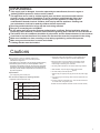 3
3
-
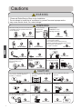 4
4
-
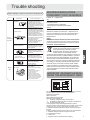 5
5
-
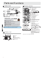 6
6
-
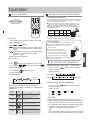 7
7
-
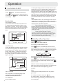 8
8
-
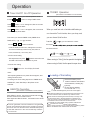 9
9
-
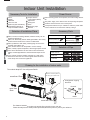 10
10
-
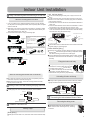 11
11
-
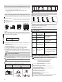 12
12
-
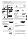 13
13
-
 14
14
-
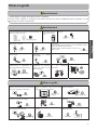 15
15
-
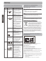 16
16
-
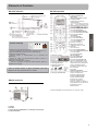 17
17
-
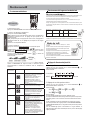 18
18
-
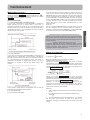 19
19
-
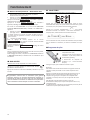 20
20
-
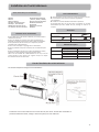 21
21
-
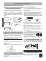 22
22
-
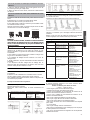 23
23
-
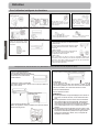 24
24
-
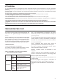 25
25
-
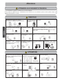 26
26
-
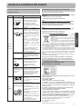 27
27
-
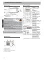 28
28
-
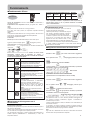 29
29
-
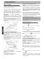 30
30
-
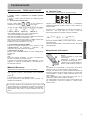 31
31
-
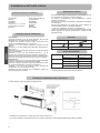 32
32
-
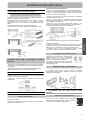 33
33
-
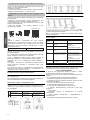 34
34
-
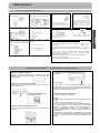 35
35
-
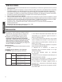 36
36
-
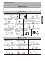 37
37
-
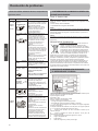 38
38
-
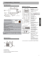 39
39
-
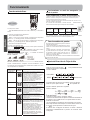 40
40
-
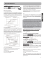 41
41
-
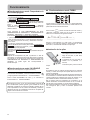 42
42
-
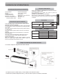 43
43
-
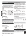 44
44
-
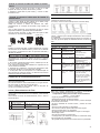 45
45
-
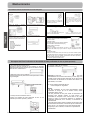 46
46
-
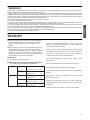 47
47
-
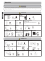 48
48
-
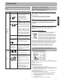 49
49
-
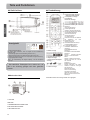 50
50
-
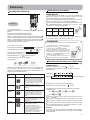 51
51
-
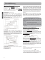 52
52
-
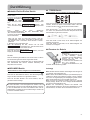 53
53
-
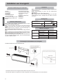 54
54
-
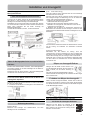 55
55
-
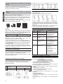 56
56
-
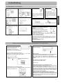 57
57
-
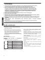 58
58
-
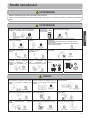 59
59
-
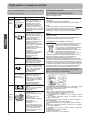 60
60
-
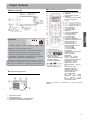 61
61
-
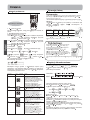 62
62
-
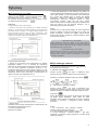 63
63
-
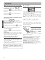 64
64
-
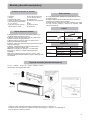 65
65
-
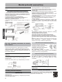 66
66
-
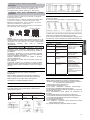 67
67
-
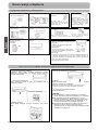 68
68
-
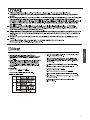 69
69
-
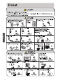 70
70
-
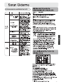 71
71
-
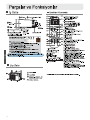 72
72
-
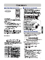 73
73
-
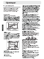 74
74
-
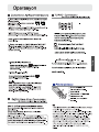 75
75
-
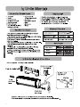 76
76
-
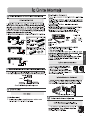 77
77
-
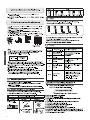 78
78
-
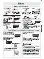 79
79
-
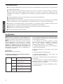 80
80
-
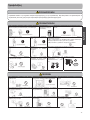 81
81
-
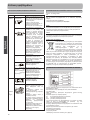 82
82
-
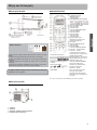 83
83
-
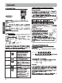 84
84
-
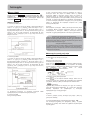 85
85
-
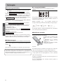 86
86
-
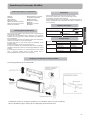 87
87
-
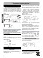 88
88
-
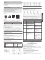 89
89
-
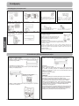 90
90
-
 91
91
-
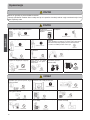 92
92
-
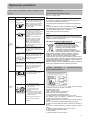 93
93
-
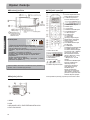 94
94
-
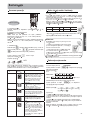 95
95
-
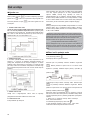 96
96
-
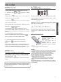 97
97
-
 98
98
-
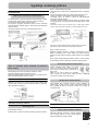 99
99
-
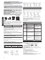 100
100
-
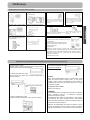 101
101
-
 102
102
-
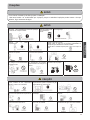 103
103
-
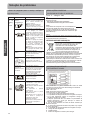 104
104
-
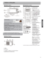 105
105
-
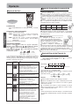 106
106
-
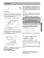 107
107
-
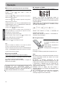 108
108
-
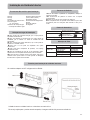 109
109
-
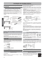 110
110
-
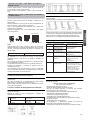 111
111
-
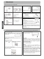 112
112
-
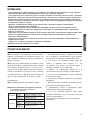 113
113
-
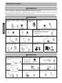 114
114
-
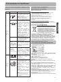 115
115
-
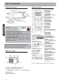 116
116
-
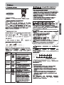 117
117
-
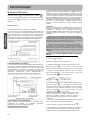 118
118
-
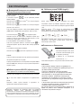 119
119
-
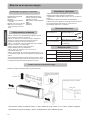 120
120
-
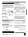 121
121
-
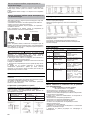 122
122
-
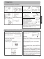 123
123


Haier AS07BS4HRA Operation Manual And Installation Manual
- Catégorie
- Climatiseurs split-system
- Taper
- Operation Manual And Installation Manual
- Ce manuel convient également à
dans d''autres langues
- italiano: Haier AS07BS4HRA
- English: Haier AS07BS4HRA
- español: Haier AS07BS4HRA
- Deutsch: Haier AS07BS4HRA
- português: Haier AS07BS4HRA
- polski: Haier AS07BS4HRA
Documents connexes
-
Haier HSU18VHJ(DB) Mode d'emploi
-
-
Haier AS24GS1ERA Le manuel du propriétaire
-
Haier AS07GS1ERA Mode d'emploi
-
-
-
-
-